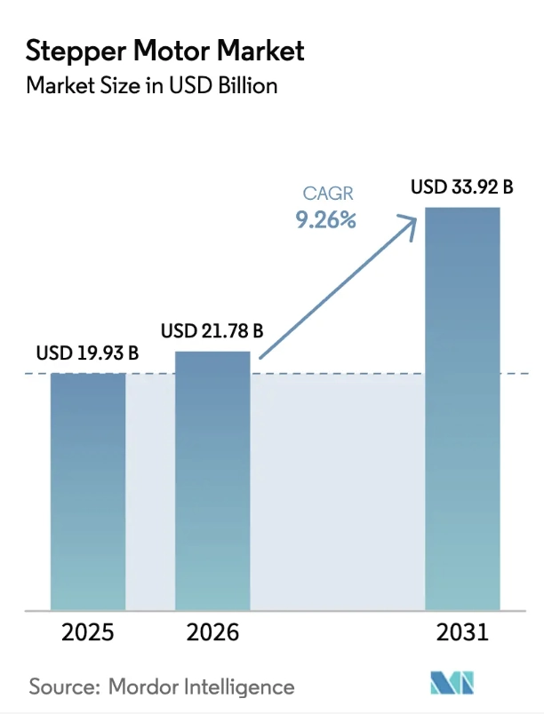
According to market forecasts from Mordor Intelligence, the global stepper motor industry is maintaining a strong growth momentum: the market size will reach USD 1.993 billion in 2025, grow to USD 2.178 billion in 2026, and is expected to expand at a CAGR of 9.26%, exceeding USD 3.392 billion by 2031.
Against this industrial background, stepper motors have become an irreplaceable core actuator in applications ranging from precision medical instruments to large-scale industrial automation equipment, thanks to their precise position control capability, excellent repeat positioning accuracy, and the ability to realize open-loop control without complex sensors.
This article provides a systematic introduction to the working principles, structural classification, and typical application scenarios of stepper motors, as well as a comparative analysis of different types of stepper motors, to help readers make more reasonable selection decisions in actual engineering projects.
Key Takeaways
- Hybrid stepper motors dominate the industrial market by combining the high torque of permanent magnets with the precision of variable reluctance designs.
- Two-phase motors offer the best cost-to-performance ratio and are the industry standard for 80% of general automation tasks.
- Three-phase systems excel in high-speed applications, retaining significantly more torque at high RPM compared to two-phase versions.
- Five-phase motors provide the ultimate solution for ultra-precision scenarios requiring minimal vibration and noise.
- Bipolar driving maximizes winding utilization, delivering 30% higher torque density than unipolar configurations.
- Permanent magnet motors serve as the most cost-effective choice for micro-load applications like camera focusing and small appliances.
- Open-loop control allows stepper motors to achieve precise positioning without expensive sensors, simplifying system architecture.
What is a Stepper Motor
A stepper motor is a special type of motor that converts electrical pulse signals into fixed-angle rotations.
In layman’s terms, you can think of electrical pulses as individual “commands”: every time a command (a pulse) is sent to the motor, it rotates a precise fixed angle, moving step by step — which is how the name “stepper motor” originated.
It has three core characteristics, which also constitute the key differences between it and ordinary motors:
Fully controllable rotation angle with no cumulative error
The total rotation angle of the stepper motor is completely proportional to the number of pulses sent. 200 pulses drive a full rotation, 100 pulses drive exactly half a rotation, and the cumulative angle error is almost zero even after 1000 rotations. No additional encoder is required for position feedback, and precise positioning can be achieved in open-loop mode, with a much lower cost than servo motors.
Fully controllable rotation speed
The speed of the stepper motor is completely proportional to the frequency of the sent pulses. The faster the pulses are sent, the faster the motor rotates, with a very wide speed regulation range from a few degrees per second to thousands of revolutions per minute (RPM).
Built-in power-off self-locking capability
Mainstream stepper motors have a holding torque when energized, which can resist a certain amount of external force. If position holding is required when power is off, a mechanical brake or a reducer with a self-locking structure (such as a worm gear reducer) needs to be installed.
How Stepper Motors Work
A stepper motor is essentially a brushless DC synchronous motor, mainly composed of two internal parts: the rotor and the stator. We will discuss the structure of different stepper motors in the classification section below.
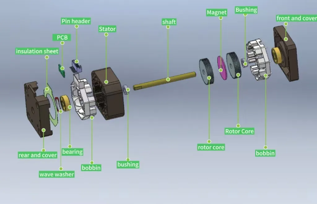
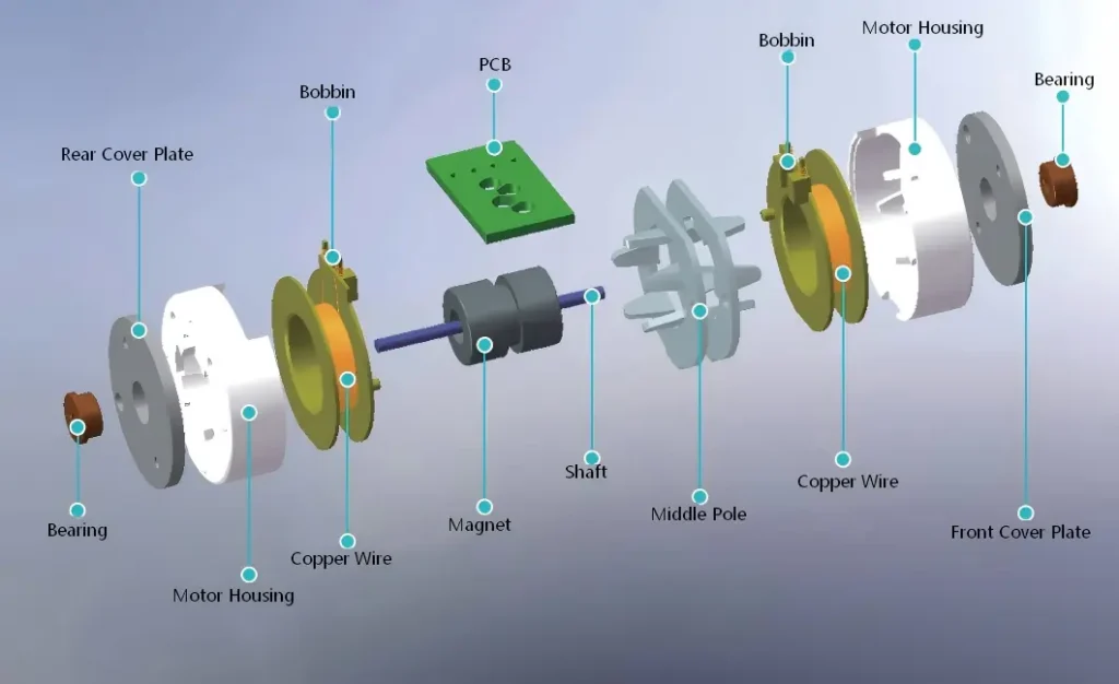
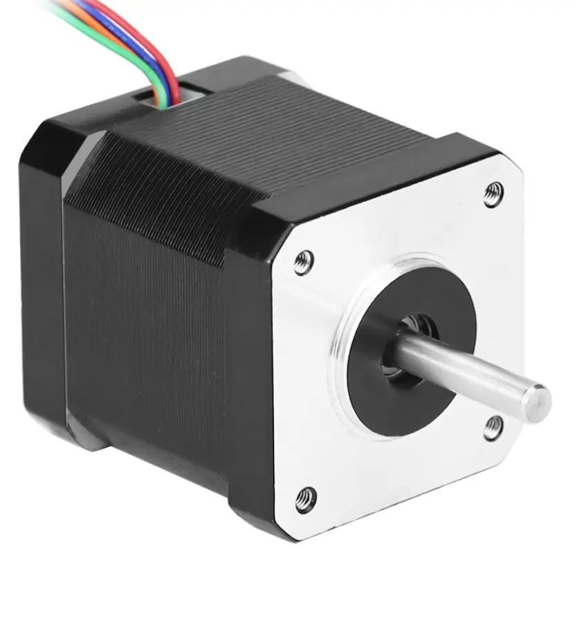
Figure 1 below is an exploded view of a hybrid stepper motor. The stator is the fixed outer part, with coils (windings) wound on it to act as an electromagnet. The rotor is the rotating part in the center, usually a permanent magnet or soft magnetic material with many small teeth.
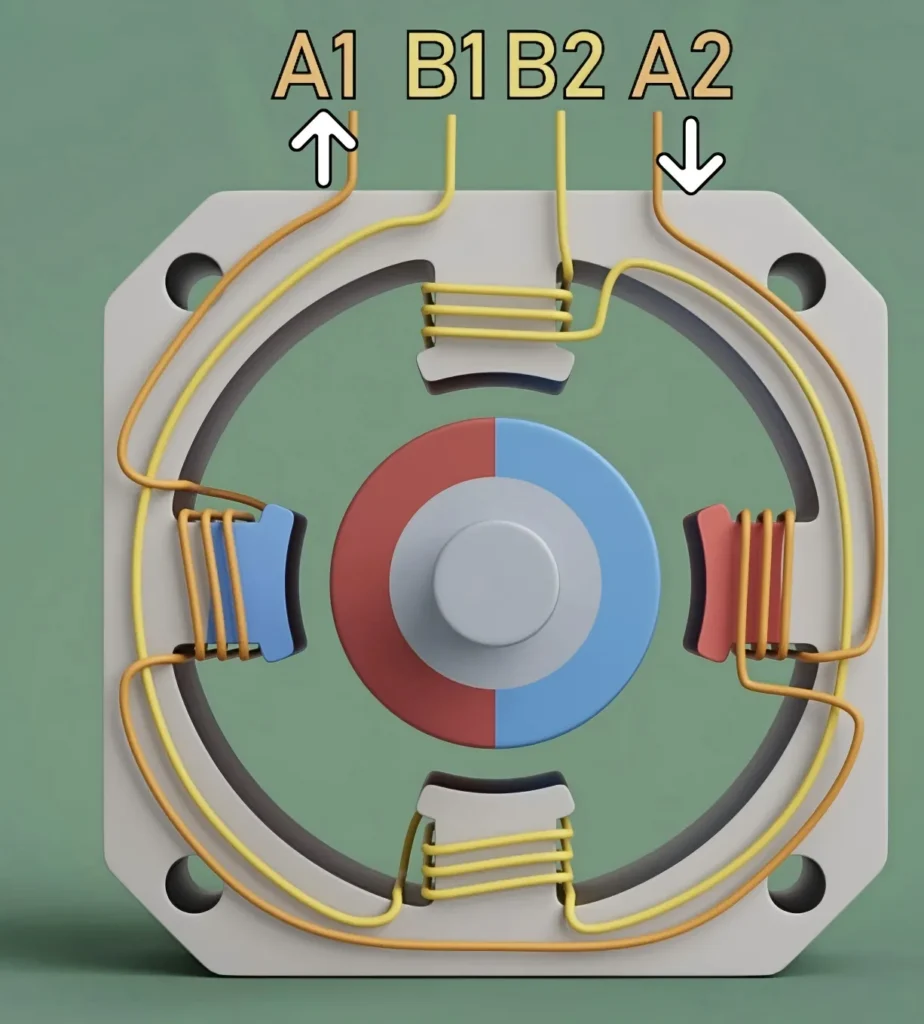
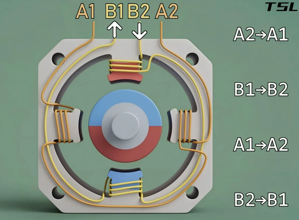
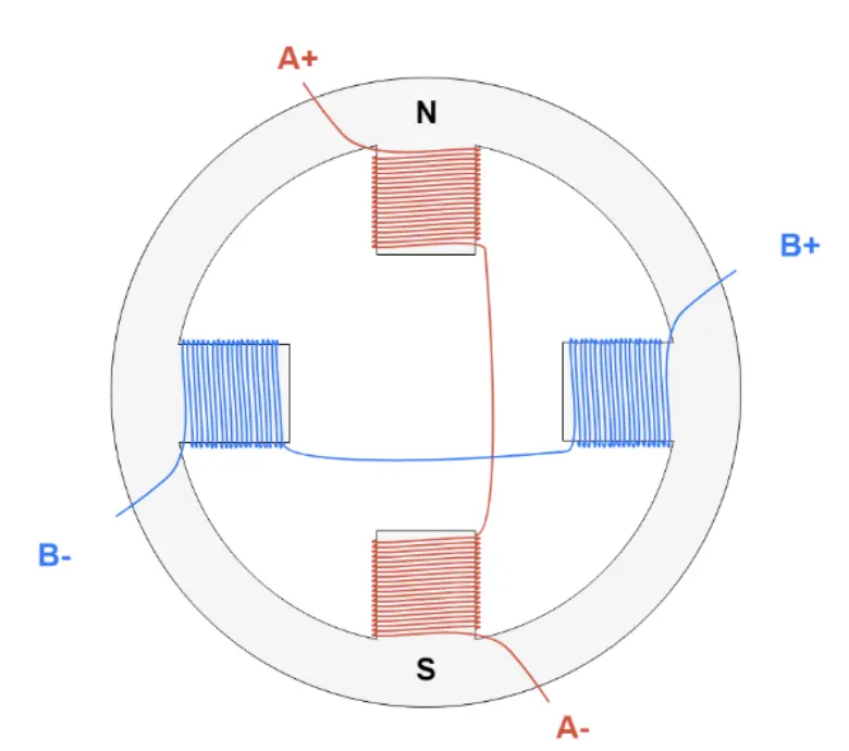
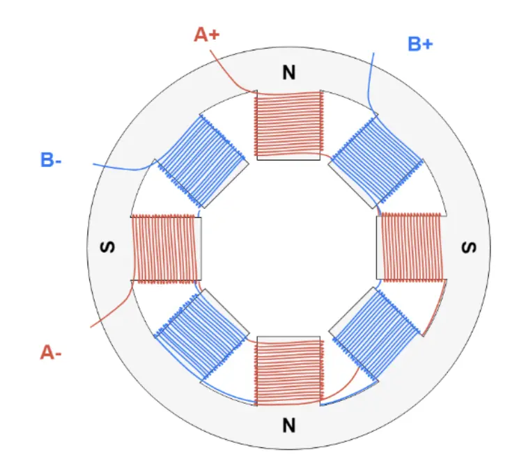
The operation of a stepper motor follows the principle of “like poles repel, opposite poles attract”. When a set of stator coils (A2→A1) is energized, this set of coils becomes an electromagnet, generating a specific north (N) and south (S) pole. At this point, the rotor is attracted by the electromagnetic force and automatically rotates to the position aligned with the stator magnetic field.Figure 2 depicts this process
When the first set of coils is de‑energized and the next set is energized, the position of the magnetic field shifts. To align with the new magnetic field again, the rotor must rotate by a fixed angle. This rotation of a fixed angle constitutes one “step” of the motor, as illustrated in Figure 3
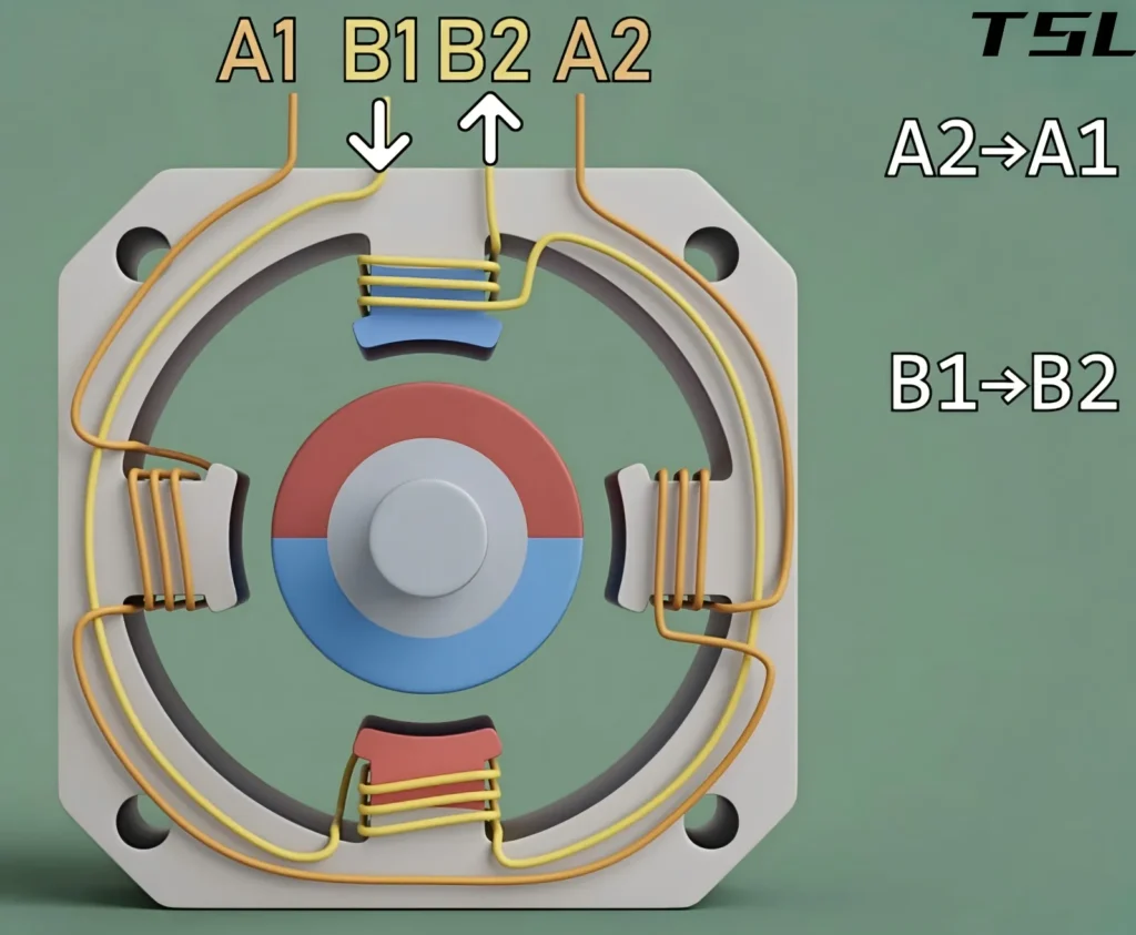
To keep the stepper motor rotating continuously, the controller (driver) must supply power to different coils in a strict logical sequence. Each current pulse makes the motor take one step. The faster the pulses are sent, the faster the motor rotates,as shown by the energizing sequence in Figure 4.
If you stop sending pulses, the motor will lock in its current position. Since you know how many pulses you have sent, you can accurately know how many degrees the motor has rotated.
Classification of Stepper Motors
Stepper motors are a broad category, with variations in step angle, control method, speed, torque and other parameters depending on their working principle and structure. For example, a driver for a hybrid stepper motor may not be able to drive a permanent magnet stepper motor, so it is critical to understand the classification of stepper motors clearly.
Classification by Rotor Structure
Stepper motors are mainly divided into three types according to the rotor structure: Variable Reluctance (VR), Permanent Magnet (PM), and Hybrid Stepper (HB). Among them, the hybrid type is the absolute mainstream in the current market, and TSL only manufactures permanent magnet and hybrid types.
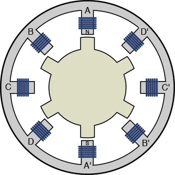
Variable Reluctance (VR) Stepper Motor
The variable reluctance stepper motor(figure 5) is a type that realizes rotation purely through reluctance change. It has been gradually replaced by the hybrid type, and is only used in niche scenarios at present.
Core Structure
Both the stator and rotor are laminated with soft magnetic materials such as silicon steel sheets, with many fine tooth slots on the surface. The rotor has no permanent magnets, and multiple sets of independent coils are wound on the stator.
Working Principle
Its core follows the principle of minimum reluctance — the magnetic field always takes the path of least resistance. When a phase of the stator coil is energized to generate a magnetic field, the rotor will automatically rotate to the position where its own tooth slots are completely aligned with those of the energized stator phase, as this position has the minimum reluctance and the most stable magnetic field.
When power is switched to the next phase of the coil, the rotor rotates to the position aligned with the tooth slots of the next phase, rotating exactly by a fixed step angle.
Core Characteristics
VR stepper motors have an extremely low rotor moment of inertia, resulting in excellent dynamic response and high-frequency start-up performance. In addition, their step angle can be made relatively small.
However, since the rotor has no permanent magnets, it has no self-holding torque (zero detent torque) when power is off, and its operating noise and vibration are usually higher than other types.
Permanent Magnet (PM) Stepper Motor
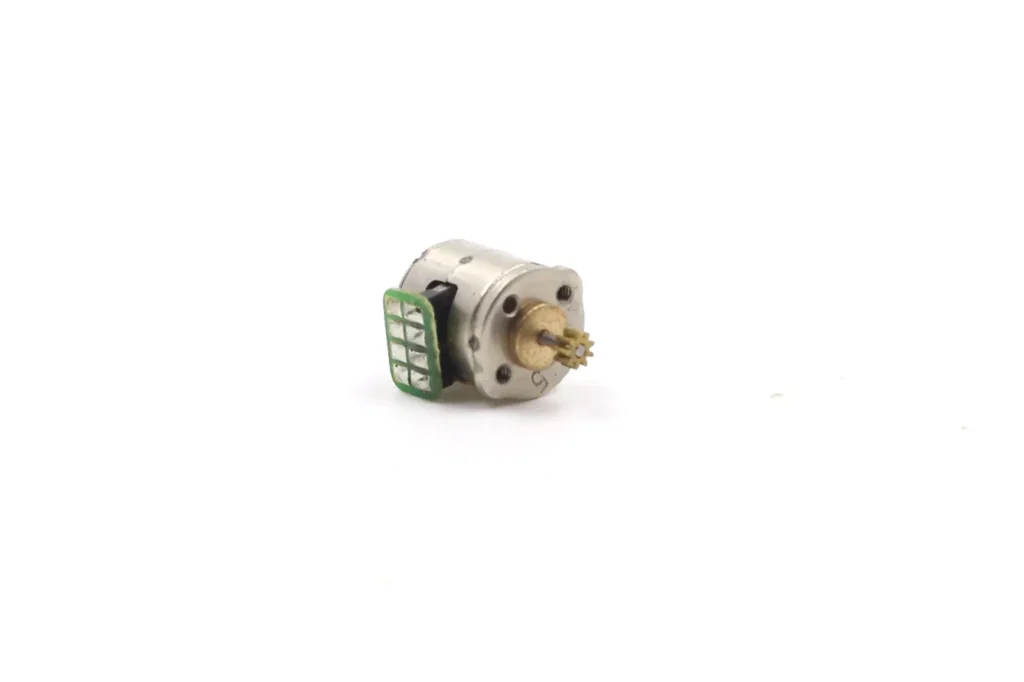
The permanent magnet stepper motor has the simplest structure and is most commonly used in lens zoom applications.
Core Structure
The rotor is made of permanent magnets with magnetic poles arranged alternately along the circumferential direction, and the stator is a winding with coils.
Working Principle
When a phase of the stator coil is energized, the stator generates corresponding N/S magnetic poles, which attract the opposite poles and repel the like poles of the permanent magnet on the rotor.
The rotor immediately rotates to the position where the two sets of magnetic poles are completely aligned. Switching the energized coil changes the magnetic pole direction of the stator, and the rotor rotates a fixed angle accordingly to complete one step.
Core Characteristics
It has a relatively large step angle, with common values of 7.5° and 15°, meaning 48 steps or 24 steps per full rotation. It features an extremely simple structure, very low cost, and low power consumption. It also has inherent holding torque when power is off due to the permanent magnet on the rotor.
However, its shortcomings are also obvious: low accuracy, low torque, proneness to jitter and step loss at high speeds, and poor high-speed performance, which need to be solved by adding a reduction mechanism.
Hybrid Stepper (HB) Motor
As the name suggests, the hybrid stepper motor combines the advantages of both permanent magnet and variable reluctance types, and is the most mainstream type in current industrial applications.
Core Structure
The rotor is divided into two sections with a ring-shaped permanent magnet sandwiched in the middle. Both sections of the rotor are provided with fine tooth slots, and the teeth of the two sections are staggered by exactly half a tooth pitch. The stator is also a multi-phase winding with tooth slots, with common specifications of two-phase, three-phase, and five-phase.
Working Principle
The permanent magnet in the middle charges the two sections of the rotor with N pole and S pole respectively, forming a fixed basic magnetic field. After the stator coil is energized, a controllable alternating magnetic field is generated, which is superimposed with the basic magnetic field of the permanent magnet.
At the same time, it cooperates with the reluctance change of the tooth slots of the stator and rotor to pull the rotor for precise rotation.
It utilizes the high torque and power-off self-locking capability brought by the permanent magnet, as well as the high precision brought by the tooth slot structure, perfectly avoiding the core shortcomings of the first two types of motors.
Core Characteristics
It has a small step angle, with common values of 1.8° for two-phase, 1.2° for three-phase, and 0.72° for five-phase, delivering high positioning accuracy. Under the same volume, its torque is much higher than the first two types.
It features stable operation, low noise, and excellent power consumption control, with inherent holding torque when power is off.
The only disadvantage is that its structure is more complex than the first two types, and its cost is slightly higher than that of permanent magnet and variable reluctance types. However, it has the best comprehensive cost performance and is the first choice for most scenarios.
Table 1 VR VS PM VS HB
| Characteristic Dimension | Variable Reluctance (VR) Stepper Motor | Permanent Magnet (PM) Stepper Motor | Hybrid (HB) Stepper Motor |
| Rotor Structure | Multi-tooth soft iron, non-magnetic | Permanent magnet | Permanent magnet + fine-tooth iron core |
| Step Angle Resolution | High (1.2° ~ 15°) | Low (7.5° ~ 15°) | Ultra-high (0.9° ~ 3.6°) |
| Output Torque Density | Low | Medium | Highest |
| Power-off Self-holding Force | None | Medium | Strong |
| Dynamic Response Speed | Extremely fast (due to low inertia) | Average | Excellent |
| Operating Noise and Vibration | High | Medium | Lowest (stable) |
| Manufacturing Cost | Low | Relatively low | Relatively high |
Classification by Stator Structure
According to the stator structure, stepper motors are divided into two-phase, three-phase and five-phase types based on the number of phases of the stator winding. From the perspective of stator winding drive, they are further divided into unipolar and bipolar types.
Number of Phases of Stator Winding
The number of phases refers to the number of independently controlled and individually excitable winding groups on the stator. By energizing the windings of different phases in a fixed sequence, the stator generates a step-by-step rotating magnetic field that pulls the rotor to rotate synchronously.
The higher the number of phases, the smaller the single rotation angle of the stator magnetic field, which corresponds to a smaller step angle of the motor, lower torque ripple, and smoother operation.
Two-Phase Stepper Motor
The mainstream type in the industry with the highest market share.
Core Structure
The industry general standard is 8 main stator poles, with every 2 opposite main poles forming a group, totaling 4 groups of main poles, divided into A and B two-phase windings, with each phase controlling 2 groups of main poles. The surface of each main pole is provided with 3-5 small teeth, which are precisely matched with the rotor tooth slots.
Working Principle
Through the four-beat cycle energization sequence of Phase A → Phase B → Reverse Phase A → Reverse Phase B, the rotor rotates a full step angle for each complete cycle of the stator magnetic field. Half-step and microstepping drives can also be used to further reduce the step length and improve smoothness.
Typical Parameters
Standard step angle of 1.8° (200 steps/revolution), high-precision version of 0.9° (400 steps/revolution), with common lead wires of 4-wire, 6-wire, and 8-wire.
Characteristics
It has a fully universal supply chain, mature drive circuits, low cost, and industry-wide interchangeable accessories, with the best comprehensive cost performance. The shortcomings are the inherent resonance zone at low speeds and rapid torque attenuation at high speeds.
Three-Phase Stepper Motor
This type of motor is generally an exclusive solution for industrial heavy-duty and high-speed applications.
Core Structure
The industry general standard is 12 main stator poles, with every 2 opposite main poles forming a group, totaling 6 groups of main poles, divided into A, B, C three-phase windings, with each phase controlling 2 groups of main poles. The requirements for tooth slot density and winding symmetry of the stator main poles are higher than those of the two-phase version.
Working Principle
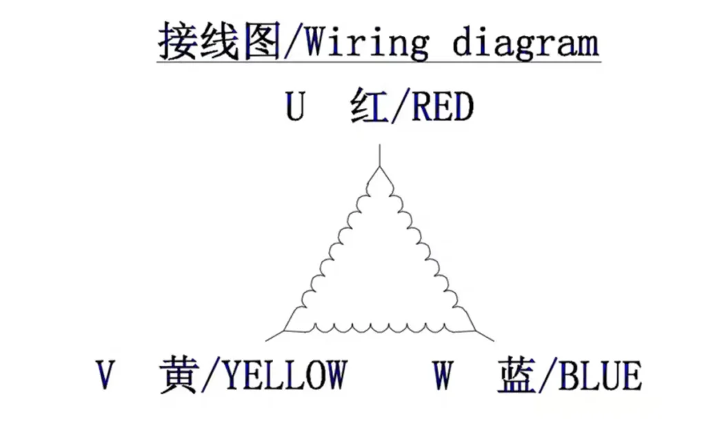
Through the three-beat sequence of Phase A → Phase B → Phase C, or the six-beat energization sequence of Phase A → Phase AB → Phase B → Phase BC → Phase C → Phase CA, the magnetic field rotates more smoothly, the single step rotation angle is smaller, and the torque ripple is significantly reduced.
Typical Parameters
Standard step angle of 1.2° (300 steps/revolution), high-precision version of 0.6° (600 steps/revolution), with common lead wires of 3-wire and 6-wire.
Characteristics
The rated torque is more than 20% higher than that of the two-phase type under the same frame size, with strong high-speed torque retention capability.
The torque attenuation at 2000-3000rpm is far less than that of the two-phase type. It has stronger overload capacity and impact load resistance, and the low-speed resonance zone is almost eliminated. The shortcoming is that the drive is not compatible with the two-phase type, resulting in higher system cost and lower accessory versatility than the two-phase type.
Five-Phase Stepper Motor
The five-phase stepper motor has the smallest market share, but is the solution for ultra-precision high-end applications.
Core Structure
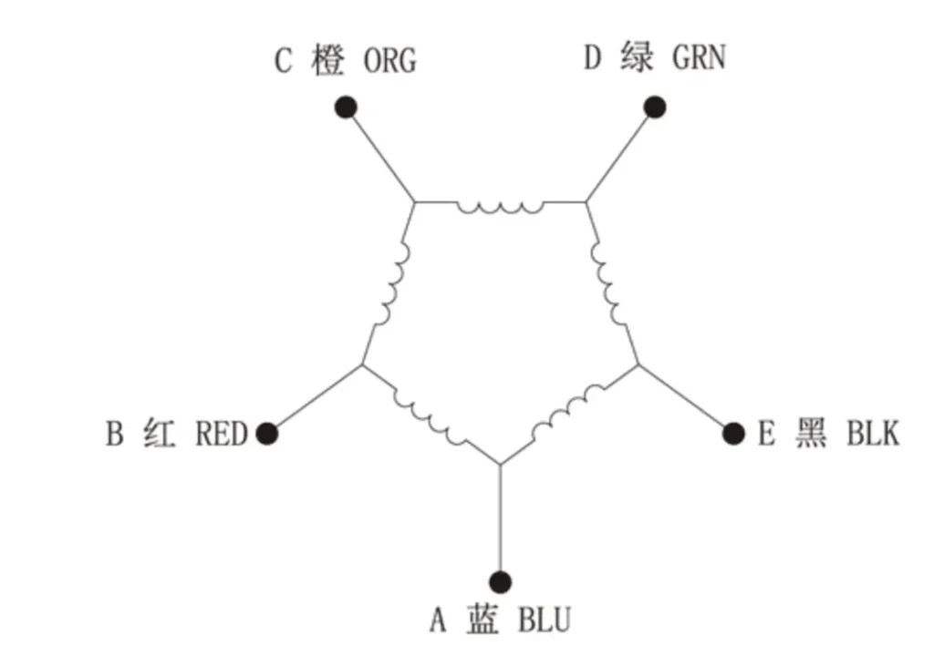
The industry general standard is 20 main stator poles, with every 2 opposite main poles forming a group, totaling 10 groups of main poles, divided into A, B, C, D, E five-phase windings, with each phase controlling 2 groups of main poles. The requirements for the machining accuracy of the stator core, winding symmetry, and inductance consistency are extremely high, with tolerance control at the micron level.
Working Principle
Through the five-phase ten-beat cycle energization sequence, the single rotation angle of the stator magnetic field is extremely small, the step angle is greatly reduced, and the torque ripple is only about 20% of that of the two-phase type, with almost no inherent resonance zone.
Typical Parameters
Standard step angle of 0.72° (500 steps/revolution), high-precision version of 0.36° (1000 steps/revolution), with common lead wires of 5-wire and 10-wire.
Characteristics
It delivers top-tier positioning accuracy, low-speed smoothness, and noise control, with minimal overshoot in single-step response, enabling ultra-smooth microstepping operation without additional dampers.
The shortcoming is that the drive is completely incompatible, and must be matched with the original factory dedicated driver. The system cost is 5-10 times that of the two-phase type, with extremely poor supply chain versatility and high later operation and maintenance difficulty.
Table 2 :Two-Phase VS Three-Phase VS Five-Phase
| Characteristic Dimension | Two-Phase Stepper Motor | Three-Phase Stepper Motor | Five-Phase Stepper Motor |
| Stator Core Structure | 8 main poles, 2 sets of independent windings | 12 main poles, 3 sets of independent windings | 20 main poles, 5 sets of independent windings |
| Standard Step Angle | 1.8° (200 steps/rev), 0.9° | 1.2° (300 steps/rev), 0.6° | 0.72° (500 steps/rev), 0.36° |
| Torque Ripple Coefficient | Baseline 100% | Approx. 60% | Approx. 20% |
| High-Speed Torque Performance | Sharp torque drop after 2000rpm | Retains 60% rated torque at 3000rpm, 30%+ better than two-phase | Smooth at low speed, high-speed performance better than two-phase, slightly inferior to three-phase |
| Rated Overload Capacity | 1.5 times | 2 times (strongest impact resistance) | 1.8 times |
| Single-Step Positioning Error | ±3%, no cumulative error | ±2.5% | ±1.5% (highest accuracy) |
| Drive Compatibility | Industry-wide universal, 1:1 interchangeable | Requires dedicated drive, average versatility | Original factory exclusive drive, no interchangeability |
| System Cost | Baseline 100% | Approx. 180% | 500%-1000% |
| Core Application Scenarios | General full scenarios (80% market share) | High-speed heavy-duty industrial scenarios | Ultra-precision high-end scenarios |
Stator Winding Drive
According to the drive structure of the stator winding, there are two types: unipolar and bipolar. The difference between them lies in whether the current direction of the stator winding is controllable and whether the winding has a center tap.
Unipolar Stepper Motor
Core Structure
Each phase winding is equipped with a center tap, and consists of two coils with exactly the same number of turns and opposite winding directions. The common terminal of the two coils is the center tap.
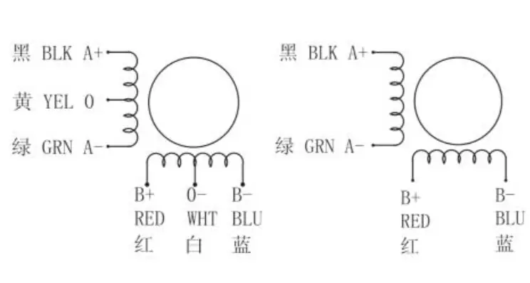
One phase winding has 3 outlet terminals, and a two-phase motor commonly has 5 wires (combined common tap), 6 wires (independent tap for each phase), and 8 wires (independent outlet for dual coils of each phase).
Working Principle
The current in the winding can only flow in one direction, without the need to switch the current direction. The polarity of the stator magnetic pole can be changed only by controlling the on-off of the two coils of the same phase.
For example, for the Phase A winding, the center tap is connected to the positive pole of the power supply. When the A+ coil is energized, the stator generates an N pole; when the A- coil is energized, the stator generates an S pole. The current direction is always from the center tap to the end of the coil throughout the process, with only unidirectional conduction, hence the name “unipolar”.
Characteristics
The drive circuit is extremely simple, no H-bridge is required, and only a single transistor/MOSFET is needed to control one coil, resulting in very low drive cost.
However, the winding utilization rate is only 50% (only half of the coil of one phase works at the same time), the output torque is about 30% lower than that of the bipolar type under the same volume, with fast high-speed torque attenuation, large inductance, and poor high-frequency response.
Bipolar Stepper Motor
Core Structure
Each phase winding has no center tap, and one phase winding is only 1 complete coil (two-phase 4-wire), or 2 independent coils that can be connected in series or parallel (two-phase 8-wire), with no common outlet terminal.
Working Principle
The current in the winding can flow in both directions. The polarity of the stator magnetic pole can be changed by switching the forward and reverse direction of the current in the same phase coil through the H-bridge drive circuit. For example, for the Phase A coil, current flows from left to right, and the stator generates an N pole; current flows from right to left, and the stator generates an S pole. One coil can realize magnetic fields in two directions, and the current can be conducted in both directions throughout the process, hence the name “bipolar”.
Characteristics
The winding utilization rate is 100%. Under the same volume and current, the output torque is more than 30% higher than that of the unipolar type, and the low-speed high-torque characteristics and high-speed torque retention capability are comprehensively better than the unipolar type.
The drive circuit requires an H-bridge, which is more complex than the unipolar type. However, the current drive chip supply chain is fully mature, and the cost difference has become minimal. It is the absolute mainstream in current industrial scenarios.
| Characteristic Dimension | Unipolar | Bipolar |
| Winding Core Structure | With center tap, dual coils | Without center tap, single/dual coils |
| Winding Utilization Rate | 50% | 100% |
| Output Torque at Same Volume | Baseline 100% | 130%+ |
| High-Speed Torque Performance | Poor | Excellent |
| Drive Complexity | Extremely low | Medium |
| Comprehensive Cost | Low | Controllable |
| Core Positioning | Low-cost civilian version | Preferred for general industrial use |
Typical Application Scenarios and Advantages of Stepper Motors
The core logic of selecting a stepper motor is “matching on demand”. There is no need to blindly pursue high precision and a high number of phases; the most suitable one is the best. Below we clarify the scenarios where each type of motor is most suitable to help you make accurate selections.
Permanent Magnet Stepper Motor
Its core positioning is a precision actuation solution that balances miniaturization, low power consumption, quietness and cost control in micro-load scenarios.
Typical scenarios are divided into two core categories:
General low-cost civilian scenarios
Swing motors for air conditioners/humidifiers, clutch drive for smart door locks, paper feeding mechanisms for thermal receipt printers/small printers, electric toys for children, on-off control of small water valves/gas valves, and air valve adjustment for household fresh air systems.
Precision micro-motion optical scenarios
Lens focusing for household/portable projectors, auto focus and aperture adjustment for mobile phone/compact cameras, zoom control for security monitoring lenses. Such scenarios generally use lead screw integrated permanent magnet linear stepper motors, which can achieve micron-level linear feed accuracy through microstepping drive + precision lead screw transmission.
Variable Reluctance Stepper Motor
Due to its obvious core shortcomings, it has been basically replaced by hybrid stepper motors at present, and is only used in a few specific scenarios, such as old high-speed plotters, high-speed thread feeding mechanisms of textile machinery, simple high-speed punching equipment, and high-speed reciprocating motion mechanisms that do not require power-off positioning.
Two-Phase Hybrid Stepper Motor
It is the most widely used type at present, covering more than 80% of general positioning scenarios, and can handle all applications except for ultra-extreme precision or torque requirements.
Typical scenarios include: 3D printers, writing machines, desktop engraving machines, monitoring pan-tilt/photography slides, semi-automatic labeling machines/filling machines, positioning modules for automated production lines, syringe pumps/infusion pumps for medical equipment, household smart curtains, and auxiliary shafts of small CNC machine tools.
Three-Phase Hybrid Stepper Motor
Its core positioning is “industrial-grade heavy-duty stable operation”, suitable for industrial equipment with high torque requirements, large loads, and the need for continuous long-term operation.
Typical scenarios include: large CNC engraving machines, feeding/cutting mechanisms of packaging machinery, auxiliary joints of industrial robots, feed shafts of CNC machine tools, handling and positioning platforms for large materials, and motion axes of laser cutting equipment.
Five-Phase Hybrid Stepper Motor
Its core positioning is “ultimate precision and smoothness”, and it is only used in high-end scenarios with extreme requirements for positioning accuracy, operating jitter, and noise.
Typical scenarios include: Positioning platforms for semiconductor wafer manufacturing, precision optical inspection instruments, military-grade servo positioning systems, high-precision medical testing equipment (such as CT machine bed drive), and ultra-precision processing equipment for 3C products.
How to Select the Right Stepper Motor
In the final analysis, the core value of a stepper motor is to achieve precise open-loop positioning at an extremely low cost, making it one of the most basic and commonly used actuators in automation equipment. When selecting a model, you can follow this minimalist logic to avoid mistakes:
- For extremely low budget, low accuracy requirements, and low torque demand, choose the permanent magnet type.
- For general scenarios, priority on cost performance, and easy access to accessories, the two-phase hybrid type is the first choice.
- For industrial heavy loads, requirements for higher smoothness and overload capacity, choose the three-phase hybrid type.
- For ultra-precision scenarios with extreme requirements for jitter and noise, choose the five-phase hybrid type.
- For variable reluctance stepper motors, they can now be directly replaced by two-phase hybrid types in most cases, and no priority consideration is needed.
Conclusion
As a mature control technology, stepper motors are gaining new vitality through in-depth integration with electronic drive technology and sensing technology.
From the initial simple open-loop drive to today’s intelligent motion control units integrated with microstepping algorithms, back EMF detection, and fieldbus (such as EtherCAT, CANopen), stepper motors are continuously expanding their control boundaries into the field of servo motors while maintaining their economy and simplicity.
In the future, with the application of artificial intelligence algorithms in motor control, stepper systems will be able to automatically identify resonance points and perform adaptive filtering, and even realize predictive maintenance of equipment life through current characteristic analysis.
For modern engineers, understanding the classification principles and application fields of stepper motors is not only the basis for designing an efficient control system, but also the core path to explore the rhythm of the physical world through precise electromagnetic interaction.
FAQ
Q1:How do I choose between a 2-phase and a 3-phase stepper motor?
The decision depends on your speed and vibration requirements. Choose 2-phase for low-speed applications (< 600 RPM) where cost is a priority. Choose 3-phase if you need high-speed stability (up to 2000+ RPM) and significantly lower resonance/vibration, as 3-phase motors have much smaller torque ripple.
Q2:Is “Holding Torque” the same as the torque I get during operation?
No. Holding Torque is the maximum torque the motor produces at a standstill. As the motor starts spinning, torque drops rapidly due to back EMF. Always consult the Torque-Frequency Curve and select a motor with a 30% to 50% safety margin over your actual required operating torque.
Q3:When should I upgrade from an “Open-Loop” to a “Closed-Loop” stepper?
Upgrade to a Closed-Loop system (stepper + encoder) if “losing steps” would cause equipment damage or expensive scrap. Closed-loop motors eliminate positioning errors, reduce heat generation, and allow for much faster acceleration/deceleration without the risk of stalling.
Q4:How does the number of lead wires (4, 6, or 8) affect my selection?
4-wire: Easiest to connect; dedicated to bipolar drivers.
6-wire: Versatile; can be used for unipolar or bipolar (high-speed) configurations.
8-wire: Best for engineers who need to optimize performance by switching between Series connection (higher torque at low speed) and Parallel connection (higher torque at high speed).
Q5:My motor is too hot to touch. Is it about to fail?
Stepper motors are designed to run hot, often reaching surface temperatures of 70°C to 90°C. This is normal. However, if the heat is excessive, check if your driver has a “Standstill Current Reduction” feature to lower current when the motor isn’t moving, which extends the life of the insulation and bearings.