Introduction
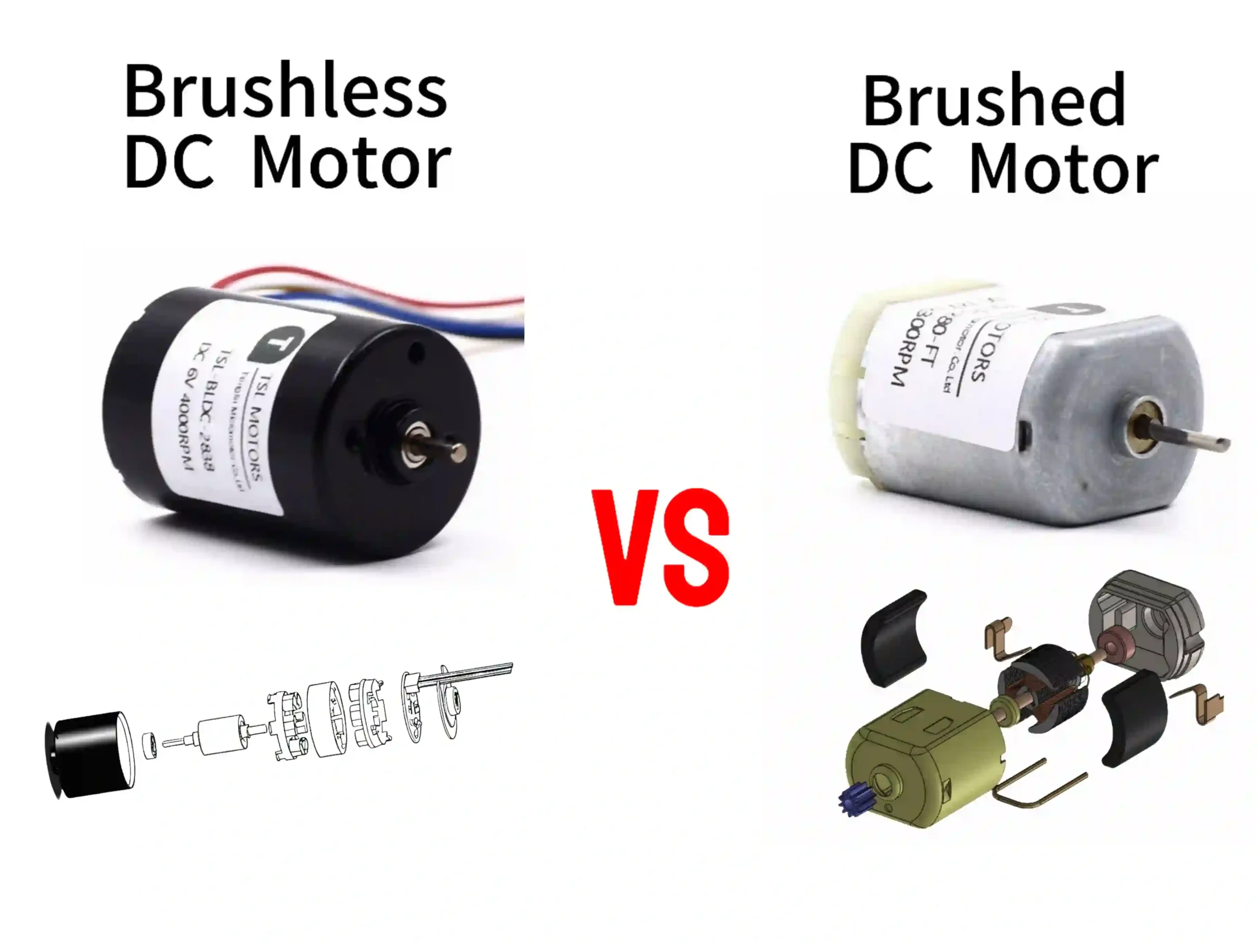
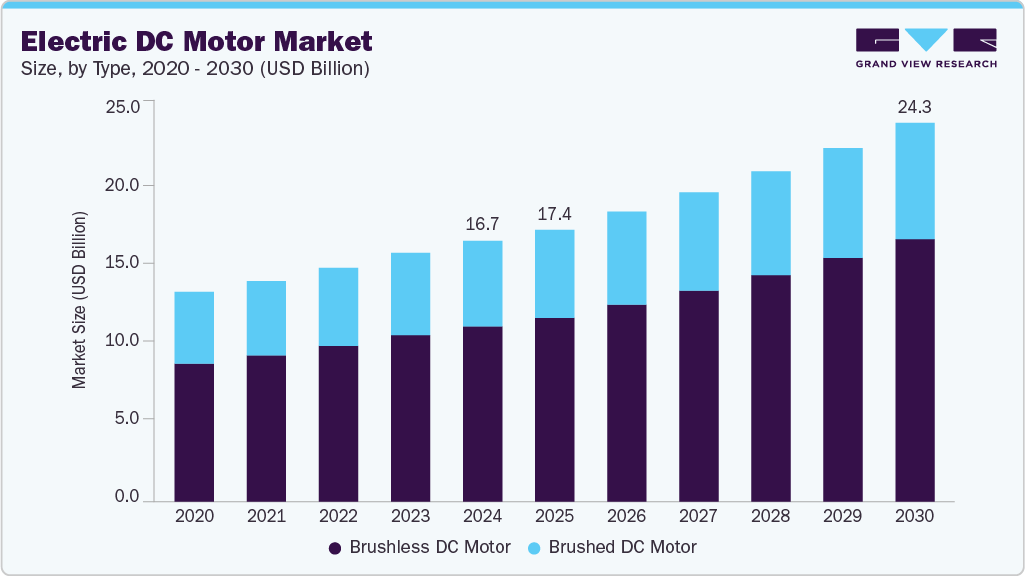
Brushless DC vs brushed motors – which one should I choose? This seems like a tough question.In the world of motor drives, Brushed DC Motors(BDC) and Brushless DC (BLDC) motors represent diverging technological paths. Brushed dc motors, with their century-old mechanical commutation simplicity, hold down the low-cost fort. BLDC motors, using electronic commutation, push the performance ceiling.
Choosing between them isn’t just a simple parameter comparison. It’s a deep dive into your application’s core needs. Are you looking for ultimate cost-effectiveness and immediate power? Or do you need long-term, zero-maintenance, intelligent drive?
This article will strip away technical jargon. It will guide you from fundamental differences to real-world scenarios. You’ll find the key to making a precise selection.
Key Takeways
- The Working Principles Of Brushless DC Motors and Brushed DC Motor
- The Structural Compositions Of Brushless DC Motors and Brushed DC Motor
- The Core Physical Principles Of Brushed DC Motors and Brushless DC Motors
- Analyze And Compare BDC And BLDC In Five Aspects: Structure, Performance, Control, Cost, And Application
- Choose Between Brushed DC Motors and Brushless DC Motors
- The Technological Evolution Trends of Brushed DC Motors and Brushless DC Motors
- FAQ For Brushed DC vs Brushless Motor
- Choose reliable brushless dc motor and brushed dc manufacturer.
DC Brushed Motors
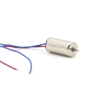
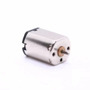
What is a brushed DC Motor
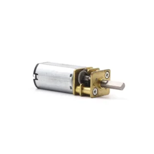
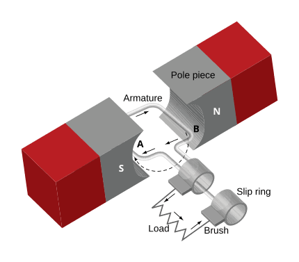
A DC brushed motor is an electric motor powered by DC. It relies on brushes and a commutator to rotate continuously. Its core components include a stator (permanent magnets or field windings) to generate a fixed magnetic field, a rotor (armature) with coiled windings, a commutator coaxial with the rotor, and brushes in contact with the commutator.
During operation, current flows through brushes into the commutator, which alternates the current direction in rotor windings. This creates continuous electromagnetic force in the stator’s magnetic field, driving rotation. The commutator-brush system ensures consistent force direction for continuous operation.
DC Brushed Motor Core Components and Functions
Stator
Function: Generates a static, fixed magnetic field.
Structure:
Permanent Magnet Stator: The most common form. Uses one or more permanent magnets (e.g., ferrite, neodymium-iron-boron) fixed to the inner wall of the motor casing. Magnetic poles typically appear in pairs (N and S poles).
Electromagnet Stator: Used in some high-power motors. Consists of coils (field windings) wound around an iron core, which generates a magnetic field when energized.
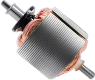
Rotor
Function: Houses the armature winding and is the rotating part of the motor. When the winding is energized, it produces electromagnetic force (Lorentz force) under the stator’s magnetic field, driving the rotor to rotate.
Structure:
Armature Core: Stacked from silicon steel sheets, forming part of the magnetic circuit and supporting the windings.
Armature Winding: Made of insulated copper wire wound in the core slots. Usually contains multiple coils connected in a specific pattern. The ends of the windings connect to the commutator’s copper segments.
Commutator
Function: Automatically switches the direction of current in the rotor windings as the rotor spins. This is crucial for achieving continuous unidirectional rotation!
Structure: A cylinder mounted on the rotor shaft, rotating with the rotor. Composed of multiple insulated arc-shaped copper segments (called commutator segments), usually equal to the number of winding coils or a multiple thereof. Each segment connects to the end of a specific coil in the armature winding.
Brushes
Function: Connects the stationary DC power supply to the rotating commutator (and thus to the rotor windings). Typically made of graphite or metal-graphite composites, they slide on the commutator surface to provide an electrical path while allowing relative motion.
Structure: Usually one or more pairs (depending on the design) of carbon or metal brushes fixed to the motor end cap (stationary part), maintaining good contact with the rotating commutator surface under spring pressure.
How Does a Brushed DC Motor Work
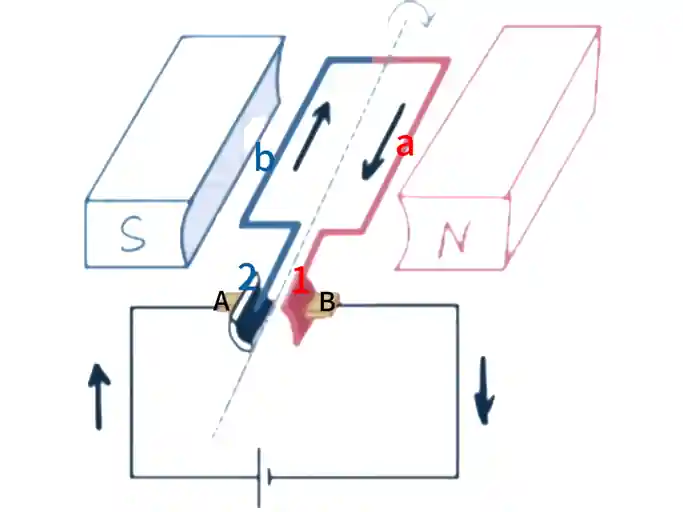
Imagine a simple DC motor. The stator has a pair of permanent magnets (North and South poles). The rotor has a single coil. The commutator has two segments.
1.Initial State (Position 1)
The DC power source positive terminal connects to brush A. The negative terminal connects to brush B.
Brush A touches commutator segment 1. Brush B touches commutator segment 2.
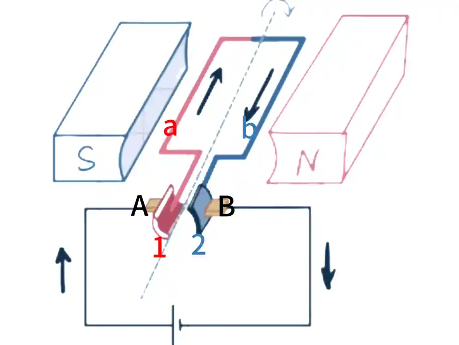
Current Path: Positive terminal → Brush A → Segment 1 → Coil side ‘a’ → Coil side ‘b’ → Segment 2 → Brush B → Negative terminal.
Current Direction: Assume current in coil side ‘a’ flows into the page. Current in coil side ‘b’ flows out of the page.
Applying Left-Hand Rule (Motor Rule):
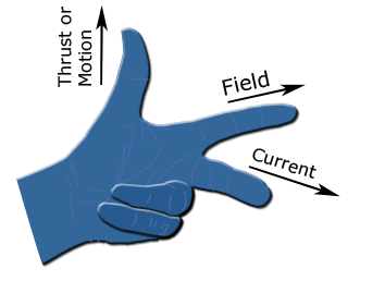
Extend your left hand. Your thumb, index, and middle fingers are mutually perpendicular.
The index finger points to the magnetic field (N → S).
The middle finger points to the current direction.
The thumb points to the force direction.
Forces:
Under the N pole (magnetic field to the left): Coil side ‘a’ (current into page) experiences an upward force.
Above the S pole (magnetic field to the right): Coil side ‘b’ (current out of page) experiences a downward force.
These forces create a torque. This counter-clockwise torque drives the rotor, starting its rotation.
2.Rotating (Position 2)
The rotor rotates clockwise by about 90 degrees. It reaches the neutral plane. Here, the coil plane is parallel to the magnetic field lines.
At this instant:
Brushes A and B are exactly on the insulating gap between the segments (or simultaneously touch both segments).
No current flows through the coil (or the current is short-circuited).
The coil sides no longer effectively cut magnetic field lines. The electromagnetic force disappears.
However, the rotor’s inertia carries it past this neutral position.
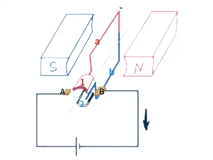
3.Commutation (Position 3)
The rotor continues rotating counter-clockwise past 90 degrees (e.g., 135 degrees).
A crucial action occurs: Brush A slides from segment 1 to segment 2. Brush B slides from segment 2 to segment 1!
Current Path Changes: Positive terminal → Brush A → Segment 2 → Coil side ‘b’ → Coil side ‘a’ → Segment 1 → Brush B → Negative terminal.
Current Direction Reverses: Now, current in coil side ‘a’ flows out of the page. Current in coil side ‘b’ flows into the page.
4.New Half-Cycle Drive (Position 4)
After the current direction reverses:
Under the N pole (magnetic field to the left): Coil side ‘a’ (current out of page) experiences a downward force.
Above the S pole (magnetic field to the right): Coil side ‘b’ (current into page) experiences an upward force.
The forces created by this pair still produce a counter-clockwise torque!
The rotor continues its counter-clockwise rotation.
5.Continuous Rotation
Every half rotation (180 degrees), the commutator automatically reverses the current direction in the rotor winding via the sliding brushes.
This current reversal always ensures the following:
The current in the conductor under the N pole generates a force that pushes the rotor in the desired direction (e.g., counter-clockwise).
Similarly, the current in the conductor above the S pole also generates a force that pushes the rotor in the same direction.
Thus, even with a stationary stator magnetic field, the changing current direction in the rotor winding produces a continuous electromagnetic torque. This torque always drives the rotor in a fixed direction.
Core Physical Principles
Here’s a summary of the core physical principles behind DC motor operation:
Ampere’s Force / Lorentz Force
A current-carrying conductor in a magnetic field experiences a force. Fleming’s Left-Hand Rule determines its direction. This force is the fundamental reason for the rotational torque.
Electromagnetic Induction (Back EMF)
As the rotor winding spins in the magnetic field, its conductors cut magnetic field lines. According to Faraday’s Law of Electromagnetic Induction, a voltage is induced in the winding. The direction of this induced voltage (by Lenz’s Law or Fleming’s Right-Hand Rule) always opposes the external power supply voltage. This is why it’s called back electromotive force (back EMF).
Importance: Back EMF is a crucial characteristic of DC motor operation. It limits the armature current (I=(Vsupply−Eback)/Rarmature). As motor speed increases, back EMF rises, and armature current decreases. When the motor reaches a stable speed, the back EMF nearly equals the supply voltage (ignoring winding resistance drop). At this point, the current primarily serves to overcome friction and load torque.
Mechanical Commutation
The commutator and brush system has a core function. As the rotor rotates, it automatically and mechanically switches the polarity of the rotor winding’s connection to the external power supply. This happens at the right moment, specifically when the coil passes near the neutral plane. This ensures the electromagnetic torque always acts in the same direction, allowing for continuous rotation.
Brushless DC Motor
What is Brushless DC Motor
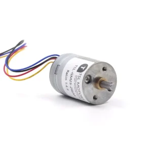
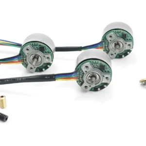
A brushless DC motor (BLDC) eliminates mechanical brushes and commutators, using electronic commutation instead. It consists of a permanent magnet rotor, a stator with windings, Hall sensors, and an electronic controller. Hall sensors detect the rotor’s position, sending signals to the controller, which switches the stator winding currents to create a rotating magnetic field. This field interacts with the permanent magnet rotor to drive rotation. Without mechanical commutation, it offers high efficiency, low noise, long lifespan, and precise speed control. Ideal for drones, new energy vehicles, smart homes, and industrial automation, it represents a reliable and intelligent modern motor technology.
Core Components and Functions of a BLDC Motor
Let’s break down the main parts of a Brushless DC (BLDC) motor and what they do.
Rotor
Function: This is the rotating part of the motor. It creates the permanent magnetic field.
Structure:
Permanent Magnets: These are the core. They’re made from high-performance materials like Neodymium Iron Boron (NdFeB) or Samarium Cobalt (SmCo). They are usually glued onto or embedded within the rotor core. The number of magnetic poles is typically even (e.g., 2, 4, 8 poles).
Rotor Core: Often made of stacked silicon steel laminations. It provides a magnetic path and supports the permanent magnets.
Rotor Shaft: This transmits the torque.
Key Point: The rotor itself has no windings and doesn’t need electricity. Therefore, there’s no need for brushes to supply power! This is what makes it “brushless.”
Stator
Function: This is the stationary part of the motor. It contains the armature windings. When these windings are energized in a specific sequence, they create a rotating magnetic field. This field attracts or repels the rotor’s permanent magnets, driving the rotor to spin.
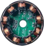
Structure:
Stator Core: Made of stacked silicon steel laminations with slots. It forms the magnetic path and reduces eddy current losses.
Armature Windings: These are coils of insulated copper wire wound into the stator core slots. The most common setup is three-phase windings (U, V, W phases), connected in a star or delta configuration. Each phase winding has multiple coils distributed across several slots to produce a smooth rotating magnetic field.
Key Point: The stator windings are the energized part. An external electronic controller precisely controls the direction of their current.
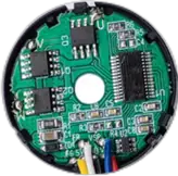
Electronic Controller
Function: This is the brain and heart of the BLDC motor. It receives DC power and signals from the position sensors. Based on the rotor’s real-time position, it precisely controls the sequence, magnitude, and direction of the current flowing through the stator’s three-phase windings. This achieves electronic commutation.
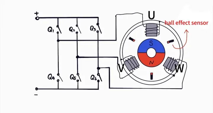
Core Circuit: A three-phase full-bridge inverter circuit. It typically consists of six power switching transistors (like MOSFETs or IGBTs). These are arranged in three half-bridges, with two switches per half-bridge (an upper and a lower switch). The midpoint of each half-bridge connects to one phase winding of the motor (U, V, W).
How it Works: The controller switches these six transistors on and off in a specific sequence. This converts the DC power (Vdc) into AC voltage/current that varies in a sinusoidal or square wave pattern across the U, V, and W phase windings. This switching sequence determines the direction and speed of the rotating magnetic field.
Position Sensors
Function: These sensors detect the real-time position of the rotor’s magnetic poles. They feed this information back to the electronic controller. The controller uses this critical information to decide when to switch the current in which two phases of the winding. This ensures the electromagnetic torque always drives the rotor in the intended direction.
Common Types:
Hall Effect Sensors: These are the most commonly used. Three Hall elements (for a three-phase motor) are mounted on the stator. They are sensitive to magnetic fields. As the rotor’s permanent magnet poles (N/S) rotate past a sensor, it outputs a high or low digital signal (a square wave). The combination of the three Hall signals forms a specific coded sequence (e.g., 001, 011, 010, 110, 100, 101). This sequence corresponds to six key rotor positions within 60-degree electrical intervals.
Optical Encoders: These offer high precision and can provide both absolute position and speed information. They include a coded disk that rotates with the rotor and fixed optoelectronic detectors. They can be incremental or absolute types.
Resolvers: These are robust and highly resistant to interference. They are often used in harsh environments (like automotive or aerospace applications). They measure angle using electromagnetic induction.
Sensorless Control: Advanced BLDC motor controllers can infer the rotor’s position by detecting the back EMF waveform generated in the stator windings. This eliminates the need for physical position sensors, reducing cost and complexity. However, it usually requires special algorithms for starting and low-speed operation.
How Do Brushless DC Electric Motors Work
Let’s imagine a simple BLDC motor. It has a 2-pole rotor (one pair of magnetic poles). The stator has three phase windings (U, V, W), spaced 120 electrical degrees apart. The controller includes a three-phase inverter bridge and three Hall sensors.
1.Initial State (Position 1 – e.g., Hall Signal 001)
Hall sensors detect the rotor is at a specific position (e.g., the North pole is near phase U).
The controller, based on its pre-set commutation logic (a “commutation table”), knows what to do. To produce maximum clockwise (CW) torque, current must flow into phase U and out of phase V. Phase W remains unpowered or “floating.”
The controller turns on the inverter bridge’s switching transistors: the upper arm U switch and the lower arm V switch.
Current Path: DC power + → Upper U switch → U phase winding → V phase winding → Lower V switch → DC power -.
Magnetic Field Generated: Phase U carries positive current (assumed to create a North pole magnetic field). Phase V carries negative current (creating a South pole magnetic field). Phase W has no current.
Torque Generation: The stator’s magnetic field points roughly from phase U (North) to phase V (South). The rotor’s permanent magnet (assuming the rotor’s North pole is currently near phase U) will be repelled by the stator’s North pole (N-N repulsion). Simultaneously, the rotor’s South pole will be attracted by the stator’s North pole (N-S attraction). These forces combine to create a clockwise (CW) electromagnetic torque, driving the rotor to spin clockwise.
2.Rotation (Position 1 → Position 2)
The rotor spins clockwise due to the electromagnetic torque.
The Hall sensors continuously monitor its position.
After the rotor rotates approximately 60 electrical degrees, it reaches a new key position (e.g., the Hall signal changes from 001 to 011).
3.Commutation Moment (Position 2 – Hall Signal 011)
The controller detects the Hall signal change (001 → 011). It knows it needs to switch to the next power state to maintain continuous torque.
The controller turns off the previously active switches (upper U switch and lower V switch).
Based on the commutation table, the controller turns on new switches: the upper arm U switch and the lower arm W switch.
Current Path: DC power + → Upper U switch → U phase winding → W phase winding → Lower W switch → DC power -.
Magnetic Field Changes: Phase U still carries positive current (North pole). Phase W now carries negative current (South pole). Phase V has no current.
Torque Maintained: The stator’s magnetic field direction shifts from phase U (North) to phase W (South). The rotor has now rotated 60 degrees. Its North pole is moving away from the original U phase position and approaching the W phase position (which is now energized as a South pole). The stator’s North pole continues to repel the rotor’s North pole, and the stator’s South pole attracts the rotor’s North pole (while the stator’s North pole attracts the rotor’s South pole). The combined forces still produce a clockwise (CW) torque.
4.Subsequent Commutations (Position 3 → Position 6)
Every time the rotor rotates 60 electrical degrees, the Hall signal changes (011 → 010 → 110 → 100 → 101 → 001).
The controller responds to these six combinations of Hall signals. It precisely follows the commutation table, switching between six different transistor activation combinations (these are the six “commutation steps”). Each state is active for 120 electrical degrees.
Example Conduction Combinations: U+V- → U+W- → V+W- → V+U- → W+U- → W+V- → back to U+V- … (and so on, in a cycle).
Each commutation ensures that the magnetic field produced by the stator consistently leads the rotor’s permanent magnetic field by an appropriate angle (typically 60-120 electrical degrees, depending on the drive method). This creates a continuous, smooth electromagnetic torque that drives the rotor in a continuous clockwise rotation.
5.Reversing Direction
To reverse the motor’s direction (counter-clockwise, CCW), the controller simply executes the above six commutation steps in reverse order (e.g., starting from U+W-, then U+V-, etc.).
Core Physical Principles of BLDC Motors
Here’s a summary of the key physical principles behind Brushless DC (BLDC) motor operation.
1.Electromagnetic Force (Lorentz Force)
Just like in brushed motors, a current-carrying conductor (here, the stator windings) experiences a force when in a magnetic field (here, the rotor’s permanent magnetic field). This force creates torque. Fleming’s Left-Hand Rule determines its direction.
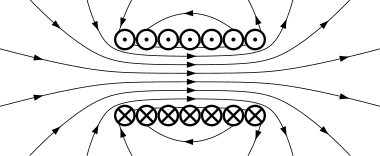
2.Generation of a Rotating Magnetic Field
The controller sequentially switches the current’s direction and combination in the three-phase windings. This generates either a stepped rotating magnetic field (for square wave drive) or a continuously smooth rotating magnetic field (for sine wave drive) within the stator’s space. This rotating magnetic field “pulls” the rotor’s permanent magnets, causing them to rotate synchronously.
3.Synchronous Motor Characteristics
In a stable state, the rotor’s mechanical speed is strictly synchronized with the stator’s rotating magnetic field speed (synchronous speed). The synchronous speed (Ns) is determined by the power supply frequency (f) and the number of motor pole pairs (P):
Ns=(120×f)/P (units: RPM)
For square-wave driven BLDCs, f is the commutation frequency (number of commutations per second / 6).
4.Back Electromotive Force (Back EMF)
As the rotor’s permanent magnets spin, their magnetic field cuts across the stationary stator windings. According to Faraday’s Law of Electromagnetic Induction, a voltage is induced in these stator windings. This is called back EMF. Its direction always opposes changes in the winding current (Lenz’s Law).
Importance:
Energy Conversion Indicator: Back EMF signifies the motor’s conversion of electrical energy into mechanical energy.
Basis for Sensorless Control: The back EMF waveform (typically trapezoidal or sinusoidal) and its zero-crossing points contain information about the rotor’s position.
Current Limitation: As motor speed increases, the back EMF’s amplitude grows. During stable operation, the applied phase voltage (Vphase) is approximately equal to the back EMF (E) plus the winding resistance voltage drop (I×R). Back EMF effectively limits the phase current.
5.Electronic Commutation: The BLDC Innovation
Electronic commutation is the core innovation of BLDC motors. Here’s how it works:
Position sensors constantly get real-time rotor position data.
An electronic controller then uses this information.
It precisely calculates and controls when to turn power switching transistors (MOSFETs/IGBTs) on and off.
This creates a rotating magnetic field in the stator windings, exactly when needed.
This entire process completely replaces the easily worn-out mechanical commutator and brushes found in brushed motors.
Brushless DC vs Brushed Motor:Which Should You Choose
Structure sets the stage, performance seals the deal, control defines the scope, cost calls the shots, and applications guide the way—this five-dimensional compass will perfectly navigate your DC motor selection journey.
Brushless DC vs Brushed Motor: Core Structure and Operating Principle Comparison
Brushed DC (BDC) motors rely on a mechanical commutation system (physical sliding contact between brushes and a commutator) to switch the direction of rotor current; the stator generates a static magnetic field. In contrast, brushless DC (BLDC) motors use electronic commutation (controller + power switches + position sensors) to precisely control the stator winding current, generating a rotating magnetic field that drives the permanent magnet rotor. The core difference lies in the energy transfer path: BDC current flows through brushes into the rotor windings, while BLDC current directly injects into the stator windings, so the rotor doesn’t need to be energized.
| Dimension | Brushless DC Motor (BLDC) | Brushed DC Motor (BDC) |
| Commutation Method | Electronic commutation (controller + power switching transistors + position sensors) | Mechanical commutation (brushes + commutator) |
| Rotor Structure | Permanent magnets (e.g., Neodymium iron boron) – no windings | Laminated silicon steel core + armature windings |
| Stator Structure | Three-phase windings (to generate a rotating magnetic field) | Permanent magnets or field windings (to generate a static magnetic field) |
| Energy Transfer Path | Stator windings are energized → magnetic field drives permanent magnet rotor | Brushes → commutator → rotor windings → magnetic field interacts with stator |
Brushless DC vs Brushed Motor: :Performance Parameter Comparison
Brushless motors consistently outperform brushed motors in efficiency (85%-95% vs. 70%-85%), power density, lifespan (>20,000 hours vs. <2,000 hours), speed limit (100,000 RPM+ vs. 20,000 RPM), and noise control. This is because they eliminate brush friction loss and commutation sparks. However, brushed motors offer the advantage of instant full-torque startup (brushless motors require controller initialization). For electromagnetic interference (EMI), brushless motors can suppress it through filtering, while brushed motors’ commutation sparks generate strong, broadband interference.
| Indicator | Brushless DC Motor (BLDC) | Brushed DC Motor (BDC) | Essential Difference |
| Efficiency | 85%–95% (no contact loss, no rotor heating) | 70%–85% (brush friction + commutation spark loss) | BLDC significantly reduces mechanical energy loss. |
| Power Density | High (compact design, heat dissipated primarily from stator) | Lower (commutator occupies space) | BLDC is suitable for high-power, miniaturized applications. |
| Lifespan | >20,000 hours (limited by bearing life) | 500–2,000 hours (limited by brush wear) | BDC requires regular brush replacement. |
| Speed Range | Wide (up to 100,000 RPM+) | Limited (commutation sparks intensify at high speeds) | BLDC has no mechanical commutation bottleneck. |
| Noise | Low (no brush friction noise) | Higher (brush vibration + commutation arc noise) | BDC’s mechanical contact generates high-frequency noise. |
| EMI | Controllable (via filtering design) | Strong (commutation sparks generate broadband interference) | BDC requires additional shielding measures for EMI mitigation. |
Brushless DC vs Brushed Motor: Control and Drive Complexity
Brushed motors only need a DC power supply to operate, with speed control achieved by simple voltage adjustment. Brushless motors must rely on a dedicated controller (containing MCU algorithms and a three-phase inverter bridge). They achieve precise speed control through PWM modulation and Field-Oriented Control (FOC), and reversing requires modifying the software commutation sequence. Developing brushless systems has a higher barrier to entry, but they support closed-loop control and offer superior dynamic response.
Brushless DC vs Brushed Motor :A Comparative Analysis
| Project | Brushless DC Motor (BLDC) | Brushed DC Motor (BDC) |
| Drive Circuit | Requires a dedicated controller (three-phase inverter bridge + MCU algorithms) | Works by directly connecting to a DC power supply |
| Speed Control | PWM voltage modulation + precise Field-Oriented Control (FOC) | Simple voltage regulation or flux adjustment |
| Reversal | Modifying commutation sequence (software control) | Switching power supply polarity (hardware operation) |
| Start-up Feature | Requires initial position detection/start-up algorithm | Self-starting (starts immediately upon power-up) |
Brushless DC vs Brushed Motor:Cost and Economic Analysis
Brushed DC motors hold an absolute cost advantage due to their simple structure, especially in the ultra-low-cost market (under $1). However, they require regular brush replacement and incur high energy loss. Brushless DC motors have higher upfront costs (permanent magnets + controller) but result in lower total cost over long-term use due to being maintenance-free and offering over 30% efficiency improvement. Selection requires balancing short-term investment with total lifecycle cost.
| Factor | Brushless DC Motor (BLDC) | Brushed DC Motor (BDC) |
| Initial Cost | Higher (permanent magnets + controller + sensors) | Very low (simple structure, mature mass production) |
| Maintenance Cost | Near zero (no wearing parts) | High (regular brush replacement/commutator cleaning) |
| Energy Cost | Long-term energy savings (wide high-efficiency range) | Higher energy consumption (especially at low speeds/high loads) |
| Applicable Scenarios | High-end equipment/long-lifecycle applications | Low-cost/short-lifecycle/simple applications |
Brushless DC vs Brushed Motor: Typical Application Scenarios
Brushed dc motors remain dominant in low-cost, low-complexity applications (toys, car window lifters, inexpensive home appliances). Brushless DC motors dominate high-performance demanding scenarios, such as electric vehicle drives, drone power, industrial servo systems, and direct-drive home appliances (AC compressors/washing machines). Special environments (cleanrooms, flammable/explosive areas) are only suitable for brushless motors due to the absence of spark risk.
| Field | BLDC Preferred Scenarios | BDC Applicable Scenarios |
| Consumer Electronics | Drone motors, computer fans, high-end power tools | Toy cars, inexpensive small fans, electric razors |
| Industrial Equipment | Servo systems, robotic arm joints, precision pumps | Conveyor belt motors, simple valve actuators |
| Transportation | Electric vehicle main drives, e-bike hub motors | Car windshield wipers, power window lifters |
| Home Appliances | Air conditioner compressors, direct-drive washing machines | Blenders, low-cost hair dryers |
| Special Environments | Cleanrooms (no sparks), flammable/explosive environments | Prohibited (spark risk) |
Technological Evolution Trends
BLDC Replacing BDC: The Tipping Point
BLDC becomes the preferred choice when any two of these needs are met: high efficiency, long lifespan, low noise, or precise control.
Shrinking Cost Gap: BLDC is steadily entering the mid-range market. This is due to optimized rare-earth permanent magnet materials and integrated controllers, such as FOC on a chip.
BDC’s Irreplaceability:
BDC remains essential for ultra-low-cost applications, typically motors under $1.
It also holds an advantage in emergency backup systems. BDC’s direct power supply is beneficial in scenarios without a controller.
Ultimate Selection Logic
Choose BLDC unconditionally if you seek high performance, long lifespan, and low maintenance.
Opt for BDC if extreme cost sensitivity and simple open-loop control are the priorities.
In high-speed, high-load, and variable-speed scenarios, BLDC’s long-term cost-effectiveness surpasses BDC’s.
Summary
Choosing between BDC and BLDC is essentially balancing short-term cost with long-term value.
If your application tolerates regular maintenance, needs instant full-torque startup, and has a strict budget (e.g., toys, simple tools), BDC remains a reliable choice.
However, if your needs point to high-speed precision control, long-life maintenance-free operation, or energy-sensitive scenarios (electric vehicles, industrial servos, smart home appliances), BLDC‘s higher initial cost will be offset by its full lifecycle advantages.
Remember: there’s no “best” motor, only the “most suitable” solution.
Grasp these five dimensions: efficiency requirements, lifespan expectations, control precision, total cost of ownership, and environmental limitations. You will navigate the technical fog and illuminate the most appropriate driving heart.
FAQ
Q1: Everyone says brushless motors are expensive, so why are high-end devices still using them? What’s their “value”?
They’re expensive due to their “invisible value”! The upfront cost of a brushless motor buys you triple returns:
Electricity Savings: 10%-30% efficiency improvement; you’ll save the cost difference in electricity in about 2 years (e.g., for an industrial fan running 24/7).
Zero Maintenance Costs: Eliminate the labor and parts expenses of annually replacing brushes or cleaning commutators for brushed motors.
Downtime Prevention: Avoid production halts caused by brush sparks (e.g., a cleanroom loss of over $100,000 per hour).Calculate the full cost: Total Cost of Ownership (TCO) = Purchase Price + Electricity Cost × Lifespan + Maintenance Cost. BLDC often wins out over its entire lifecycle.
Q2: Brushed motors have high starting torque. Can they be used in high-load starting scenarios (like a winch)?
They can be used in emergencies, but be cautious! While a brushed motor can instantly unleash 300% of its rated torque, it comes at a heavy price:
Burnout Risk: High current leads to a sharp increase in commutator sparks. Continuous stall can melt the brushes.
Drastic Lifespan Reduction: Each heavy-load start causes wear equivalent to about 10 hours of normal operation.
Alternative Solution: A brushless motor with vector control (FOC) can achieve 150% continuous overload torque without physical wear.
Q3: Does a brushless motor absolutely require a controller? Can it be connected directly to a battery like a brushed motor?
You absolutely cannot skip the controller! This is the minimum requirement for brushless motor operation:
No Controller = Paralyzed: The rotor position is unknown, and windings can’t generate an effective magnetic field.
Minimal System Cost: The simplest square-wave drive board costs around ¥20 (e.g., EG2133 chip solution), representing less than 10% of the overall machine cost.
Advanced Tip: Sensorless control (detecting back-EMF) can eliminate the need for position sensors, further reducing cost.
Q4: Will brushed motors truly be phased out? In which areas do they remain “king”?
They will persist in extreme low-cost and simple scenarios! Here are the three brushed motor strongholds:
Motor Market: Toy cars, Christmas tree turntables (a BLDC controller would cost more than the entire device).
Millisecond Instant Response: Automotive solenoid valves (brushed motors actuate immediately upon power-up; brushless require controller initialization).
Strong EMI Environments: Brushed motors have better EMI immunity than semiconductors (some auxiliary parts in MRI equipment still use brushed).
TSL-Motor: Custom Motor Solutions
Established in 2009, TSL Motor has evolved into a leading innovator in precision drive systems and specialized motor manufacturing. Our 15,000㎡ advanced production facility in Shenzhen houses a skilled workforce of 200+ professionals, delivering an annual output of 2 million units to global markets.
Continuous R&D investment in energy-efficient motor technologies
Lean manufacturing processes ensuring cost-competitive pricing
Agile production capacity scaling for batch customization
Global compliance certifications (CE, RoHS, REACH)
With dual focus on operational excellence and client success, Twin Motor empowers businesses worldwide to achieve technological differentiation. Our engineering team welcomes complex challenges across automotive, robotics, and smart infrastructure applications.
Contact our solutions center to discuss your project requirements or request our technical portfolio.
Tsinglin Motor’s Relevant DC Motor Series
-
 Custom Micro Motors13 products
 - DC Gear Motor167 products
- 6mm Planetary Gear Motor4 products
- 6mm Planetary Metal Gear Motor3 products
- Brushless Gear Motor37 products
- Micro Gear Motor92 products
- Coreless Gear Motor37 products
- N20 Gear Motor26 products
- Plastic Gearbox Motor9 products
- Standard Gear Motor15 products
- Stepper Gear Motor16 products
-
- Planetary Gear Motor56 products
- Spur Gear Motor63 products
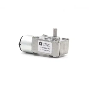
- Worm Gear Motor33 products
-
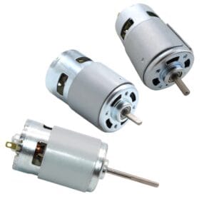
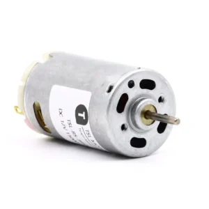
- DC Motor81 products
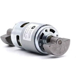
- Brushed DC Motor17 products
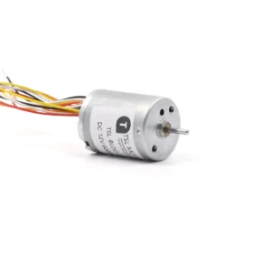
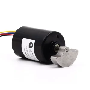
- Brushless DC Motor36 products
- Inrunner Rotor BLDC Motor8 products
- Outrunner Rotor BLDC Motor26 products
-
- Coreless DC Motor14 products
- Micro DC Motor16 products
-
- Dexterous Hand Drive Module21 products
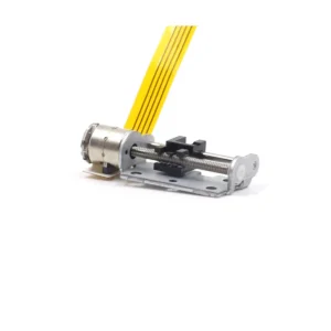
- Micro Linear Actuators9 products
- Stepper Motor32 products
- Micro Stepper Motor13 products
- NEMA Stepper Motor9 products
- Stepper Motor Linear Actuator11 products
-
- Vibration Motors71 products
- Brushless Vibration Motor8 products
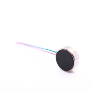
- Coin Vibration Motor22 products
- Coreless Vibration Motor3 products
- Encapsulated Vibration Motor6 products
- Linear Resonant Actuator12 products
- Powerful Vibrating Motor17 products
- SMD Vibration Motor4 products
- Sonic Vibration Motor2 products
-