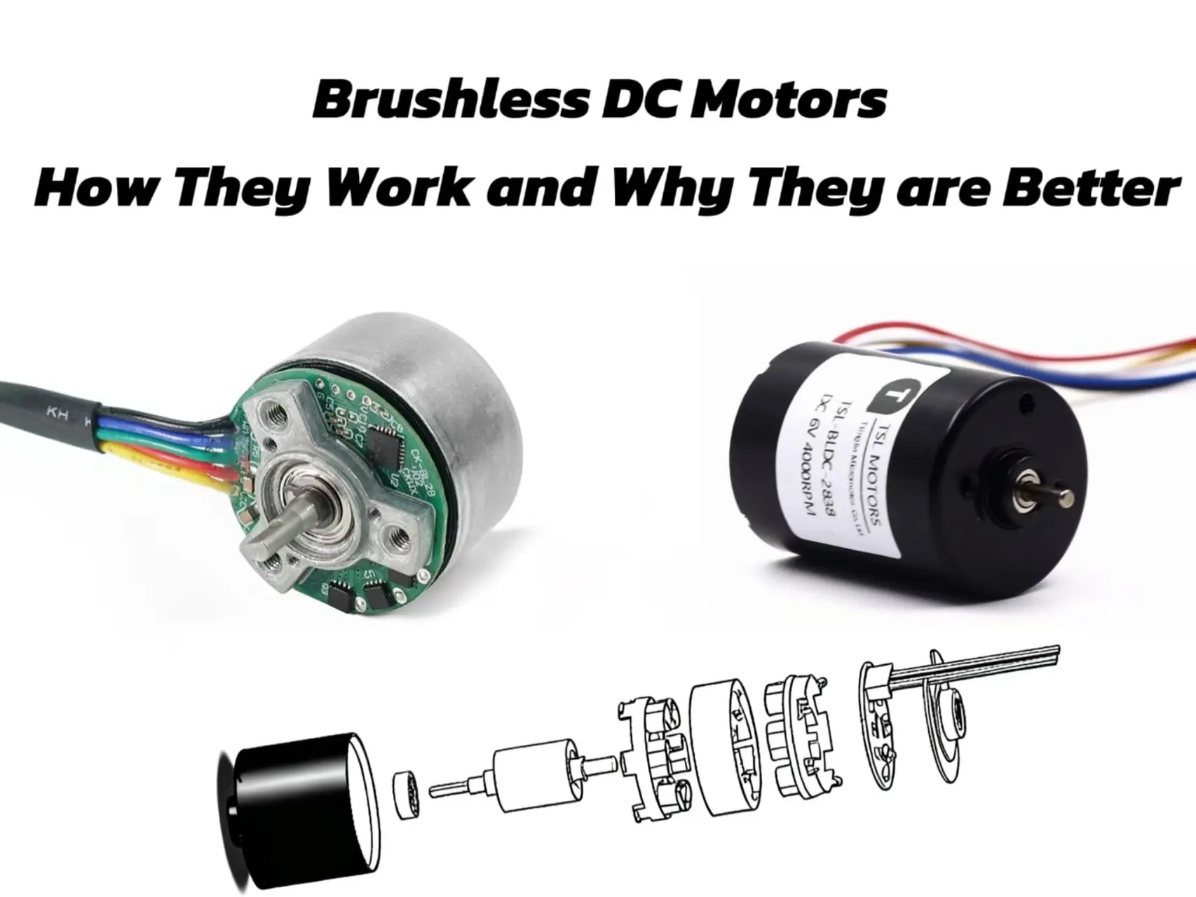
Brushless DC (BLDC) motors represent a transformative technology in modern electromechanical systems. Their core innovation lies in replacing traditional mechanical commutators with complex electronic control systems, thereby fundamentally overcoming many of the limitations inherent in their brushed predecessors.
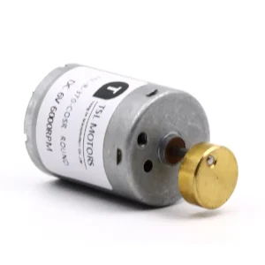
This shift in design has not only improved motor performance metrics but has also given rise to new application fields, from high-precision aerospace to everyday consumer electronics. TSL Motor is a leading DC motor manufacturer in China, offering high-quality brushless DC motors for many advanced applications.
Key Takeways
- 1.The Brushless DC (BLDC) motor replaces traditional mechanical brushes with an advanced electronic controller.
- 2.Their operation relies on the controller’s precise commutation of current to the stator windings, generating a rotating magnetic field that drives the rotor, thus providing exact control over speed and torque.
- 3.The BLDC motor’s working principle, specifically how it generates a continuous rotating magnetic field through precise electronic commutation.
- 4.It differentiates between two main structures: the inrunner, designed for high speed, and the outrunner, designed for high torque.
- 5.The critical role of the electronic controller in the BLDC system, which gives the motor its precise speed and torque control capabilities.
What is A BLDC Motor
Definition: A Synchronous, Electronically Commutated System
Technically, a Brushless DC (BLDC) motor is a type of synchronous electric motor powered by a direct current (DC) source. As the name suggests, it has no brushes. The most notable feature of a BLDC motor is its reliance on an external electronic controller for commutation, instead of the traditional mechanical brushes and commutator.
The synchronous characteristic of a BLDC motor is one of its core operating principles, meaning the rotor’s rotation remains in strict synchronous lock with the rotating magnetic field generated by the stator. This method of electronic commutation also leads to it being called an Electronically Commutated Motor (ECM).
Core Architectural Components and Their Functions
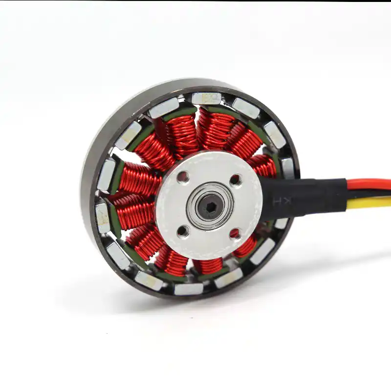
The structure of a BLDC motor can be understood as an “inside-out” version of a traditional brushed DC motor. This structural inversion is the source of many of its advantages. Its core components include the stator, rotor, and electronic controller.
Stator
The stator is the stationary part of the motor. Its core is made of laminated silicon steel sheets to minimize eddy current losses. The stator core has slots for embedding the winding coils. These windings are typically configured in three phases and can be connected in either a star (Y) or delta (Δ) configuration.
In most small BLDC motors, the three-phase star connection is the most common. The controller energizes these windings in a specific sequence to create a rotating magnetic field inside the stator. The rated voltage of the stator is a crucial design parameter chosen based on the power supply capacity.
For example, in robotics, automotive, and small drive applications, motors with lower voltages like 48V, 24V, 12V or even lower are typically preferred, while industrial automation systems use motors with a rated voltage of 100V or higher
Rotor
The rotor is the rotating part of the motor, where permanent magnets are mounted. To achieve high torque and high power density, the rotor typically uses high magnetic flux density rare-earth permanent magnet materials like Neodymium-Iron-Boron (NdFeB) and Samarium-Cobalt (SmCo).
The number of magnetic pole pairs on the rotor can range from 2 to 8 or more, depending on the application requirements, with poles arranged in an alternating North/South (N/S) sequence.
Rotor designs vary, with magnets being either Surface Permanent Magnet (SPM) or Interior Permanent Magnet (IPM). The IPM structure embeds the magnets inside the rotor, providing better mechanical integrity to withstand higher speeds.
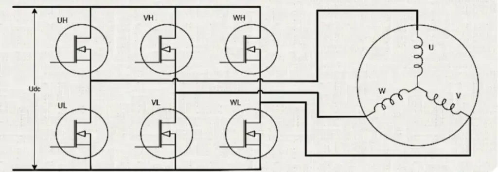
Electronic Controller (ESC)
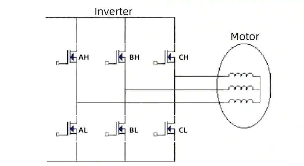
The electronic controller is the “brain” of the BLDC motor system, completely replacing the function of the mechanical commutator. This solid-state circuit typically consists of a microcontroller (MCU), gate drivers, and power switches (such as MOSFETs or IGBTs).

The controller’s main task is to monitor the rotor’s position in real time and, based on this information, switch the current in the stator windings with precise timing and sequence. Without the electronic controller, the BLDC motor cannot operate, making it an indispensable part of the system.
How Does A brushless Motor Work?
The basic working principle of a BLDC motor follows the Lorentz force law. Its operation can be broken down as follows:
1️⃣The electronic controller applies a DC voltage to one of the three stator windings (e.g., U-phase and V-phase), generating an electromagnetic field in a specific direction within the stator.
2️⃣This stator magnetic field interacts with the permanent magnetic field of the rotor. According to the principle that like poles repel and opposite poles attract, a torque is exerted on the rotor’s permanent magnets.
3️⃣This torque drives the rotor to rotate, attempting to align its magnetic field direction with the stator’s magnetic field.
4️⃣Just before the rotor reaches the alignment position, the controller switches the voltage applied to the stator windings, changing the direction of the stator’s magnetic field (e.g., switching to the V-phase and W-phase).
5️⃣The new stator magnetic field again interacts with the rotor magnets, creating a new torque that forces the rotor to continue “chasing” this continuously changing magnetic field.
6️⃣By continuously switching the current in the stator windings at a very high frequency and in a precise sequence, the controller creates a smoothly rotating magnetic field in the stator, which drives the rotor to achieve continuous, stable rotation.
What Does Brushless Mean?
The ingenuity of this design lies in its structural “inversion.” By placing the power-consuming, heat-generating windings on the stationary stator and the passive permanent magnets on the rotating rotor, this seemingly simple change has profound implications.
First, it eliminates the need to supply power to a rotating part, thereby completely dispensing with the mechanical contact components of brushes and commutators. Brushes are the primary source of wear, failure, friction loss, and electromagnetic interference in traditional motors. Their removal directly leads to a leap in the reliability, lifespan, and maintenance of BLDC motors.
Second, the heat source (the windings) is moved to the stator, which is in direct contact with the motor casing, providing an extremely efficient heat dissipation path. In contrast, in brushed motors, heat is generated in the rotor, which is trapped in the motor’s center, making heat dissipation very difficult.
Excellent heat dissipation means BLDC motors can handle higher power in a smaller volume, leading to a higher power density. Therefore, this fundamental architectural inversion is the logical starting point for all the core advantages of BLDC motor technology.
Electronically Commutated Motor
From Mechanical to Electronic: A Paradigm Shift
Commutation in brushed DC motors relies on a crude mechanical system: the rotating commutator copper segments and stationary carbon brushes make physical contact and slide to switch the current direction in the rotor coils. This process is not only inefficient but also accompanied by sparks, wear, and electrical noise.
BLDC motors achieve a fundamental paradigm shift through electronic commutation. By using semiconductor switches (like transistors) for high-speed, precise current switching, electronic commutation not only overcomes all the drawbacks of mechanical commutation but also provides unprecedented control flexibility.
The electronic controller can implement complex control strategies that are impossible with a mechanical system, such as precise speed limiting, micro-stepping for fine slow-motion control, and providing holding torque when stationary.
The Critical Role of Rotor Position Sensing
To achieve correct commutation, the controller must know the precise angular position of the rotor’s permanent magnets at all times. If the commutation timing is inaccurate, the motor will not be able to generate effective torque and may even stall or reverse.
There are two main technical paths to obtain rotor position information:
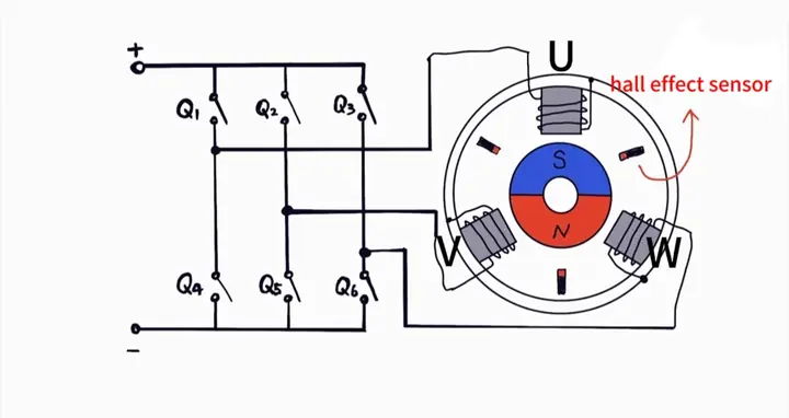
Sensored Commutation:
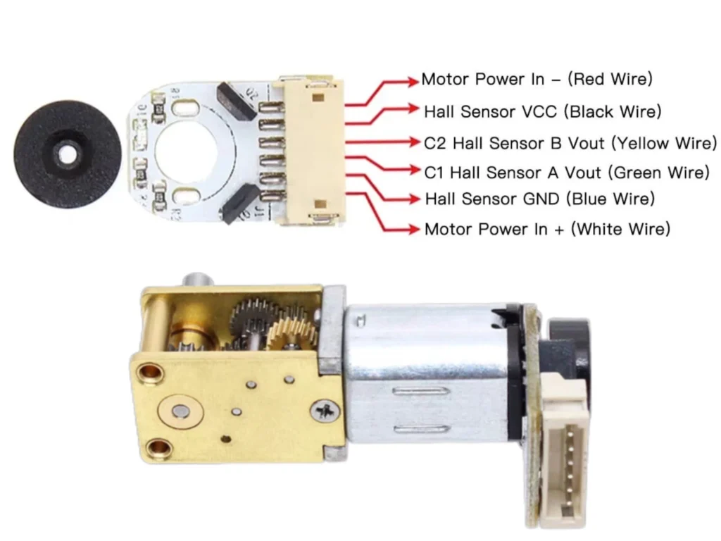
This is the most direct and reliable method, achieved by installing physical position sensors inside the motor. The most commonly used sensors are Hall effect sensors.
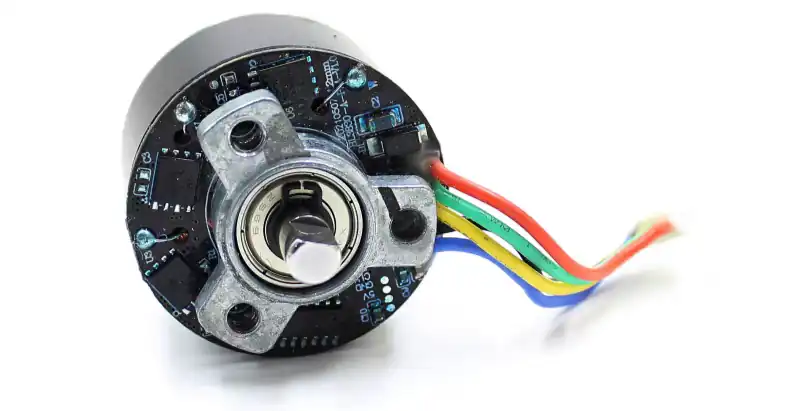
A typical three-phase BLDC motor will have three Hall sensors embedded, spaced 120 electrical degrees apart. As the rotor rotates, its permanent magnet poles (N or S) pass sequentially over these three sensors. Each sensor outputs a high or low signal based on the detected magnetic field polarity.
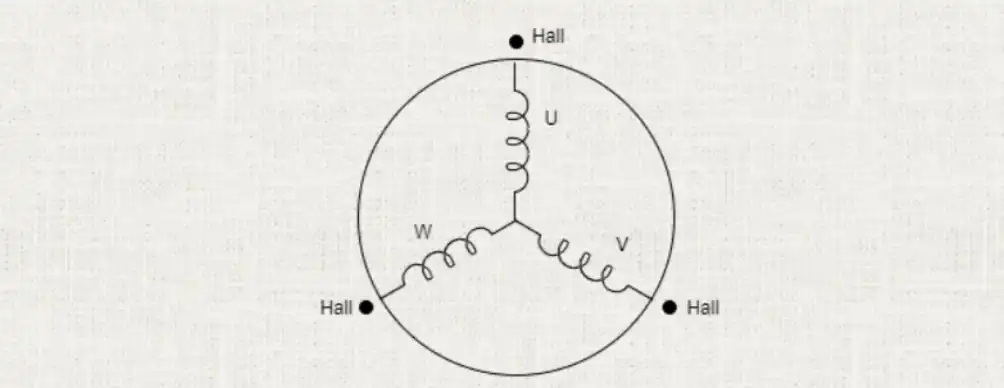
The combination of these three sensor signals (with six valid states in total) provides the controller with a real-time digital “map” of the rotor’s position, which the controller uses to decide which two windings to energize next.
The great advantage of the sensored approach is that it provides precise position feedback, ensuring smooth and reliable torque output, especially during motor startup, low-speed operation, and when the load changes dramatically.
Sensorless Commutation
Sensorless technology aims to reduce costs and simplify the motor structure by inferring the rotor position by monitoring the motor’s electrical characteristics, without physical sensors. Its core principle is the detection of Back-Electromotive Force (Back-EMF).
As the motor rotor rotates, its permanent magnetic field cuts through the stator windings. According to the law of electromagnetic induction, a voltage is induced in the winding that is not currently energized, which is the Back-EMF. The magnitude of the Back-EMF is proportional to the motor speed, and its zero-crossing point has a precise relationship with the position of the rotor’s magnetic poles.
By monitoring the Back-EMF signal on this “floating” winding, the controller can infer the rotor’s position and determine the optimal commutation timing. Sensorless control is very effective and low-cost at medium to high speeds, but its challenge lies in the startup and very low-speed stages, as the Back-EMF signal is very weak and difficult to detect accurately when the speed is too low.
Brushless DC Motor Drive
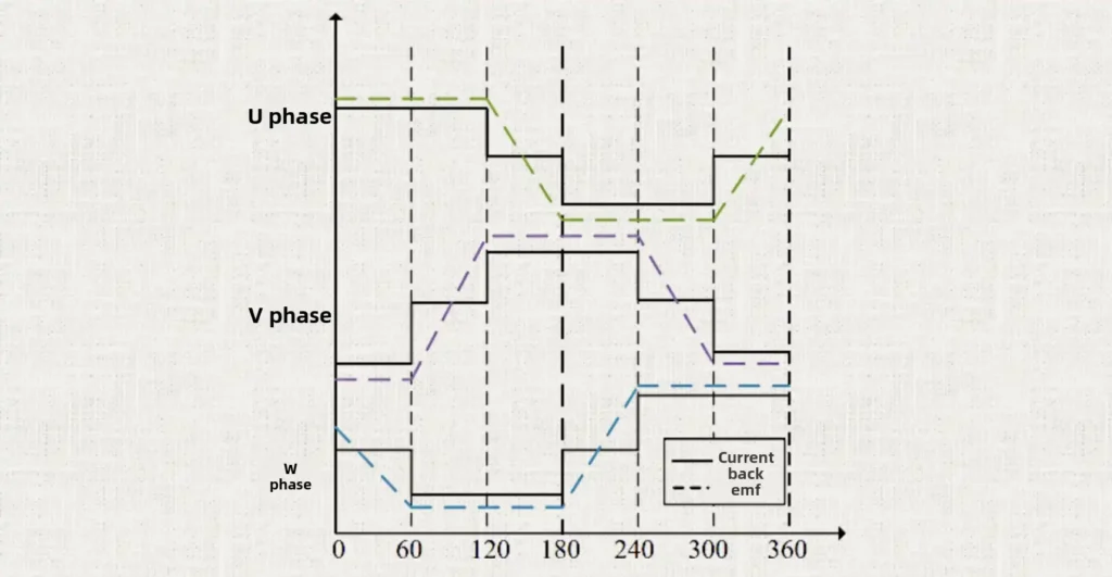
Standard BLDC motor drives typically use a method called “six-step commutation” or “trapezoidal control”. For a three-phase (U, V, W) motor, the working cycle is divided into six steps of 60 electrical degrees each.
In any single step, current flows from the positive terminal of the power supply into one phase winding and out through another to the negative terminal, while the third phase winding is left floating. The six-step commutation sequence for a complete 360-degree electrical rotation cycle is as follows:
Step 1 (0°–60°): Current flows into U-phase, out of V-phase, W-phase is floating.
Step 2 (60°–120°): Current flows into U-phase, out of W-phase, V-phase is floating.
Step 3 (120°–180°): Current flows into V-phase, out of W-phase, U-phase is floating.
Step 4 (180°–240°): Current flows into V-phase, out of U-phase, W-phase is floating.
Step 5 (240°–300°): Current flows into W-phase, out of U-phase, V-phase is floating.
Step 6 (300°–360°): Current flows into W-phase, out of V-phase, U-phase is floating.
The controller cycles through these six steps based on the rotor position detected by Hall sensors or Back-EMF sensing, causing the stator magnetic field to rotate in 60-degree increments, thus pulling the rotor’s permanent magnets to achieve continuous rotation.
Brushless DC Motor Controller: Speed, Torque, and Advanced Methods
Speed Control
The speed of a BLDC motor is typically controlled using Pulse Width Modulation (PWM) technology. Instead of simply connecting or disconnecting the windings, the controller applies voltage pulses to the power switches at a very high frequency (typically tens of kilohertz).
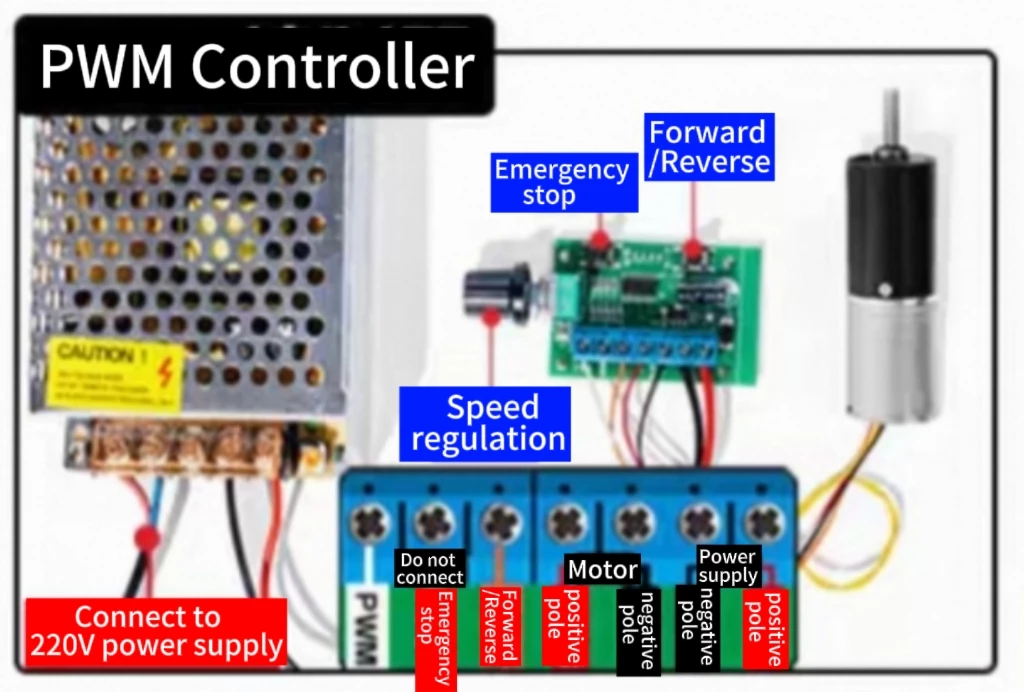
By changing the duty cycle of these pulses (the proportion of time the pulse is on within a period), the average voltage applied to the motor windings can be effectively controlled. Since motor speed is roughly proportional to the average voltage, adjusting the PWM duty cycle allows for smooth, precise control of the motor’s speed.
Torque Control
The output torque of a motor is proportional to the current flowing through its windings. Therefore, by adding a current sensor to the controller circuit and creating a closed-loop control system, the current flowing through the windings can be precisely regulated and limited, thereby achieving accurate control over the motor’s output torque.
Advanced Control Waveforms
While six-step trapezoidal control is simple to implement, its inherent drawback is that at each commutation instant, the current switches from one phase to another, causing a slight pulsation in the output torque, known as “Torque Ripple”.
This pulsation is particularly noticeable at low speeds and can cause motor vibration and audible noise. To achieve smoother and quieter operation, more advanced control algorithms have been developed, such as Sinusoidal Control and Field-Oriented Control (FOC).
Sinusoidal Control
Unlike trapezoidal control, which only applies square-wave current to two windings at a time, sinusoidal control applies smoothly varying sinusoidal current to all three windings simultaneously, with a 120-degree phase difference between them. This synthesizes a very smooth vector for the rotating magnetic field in the stator, which almost completely eliminates torque ripple, making the motor run extremely quietly and smoothly.
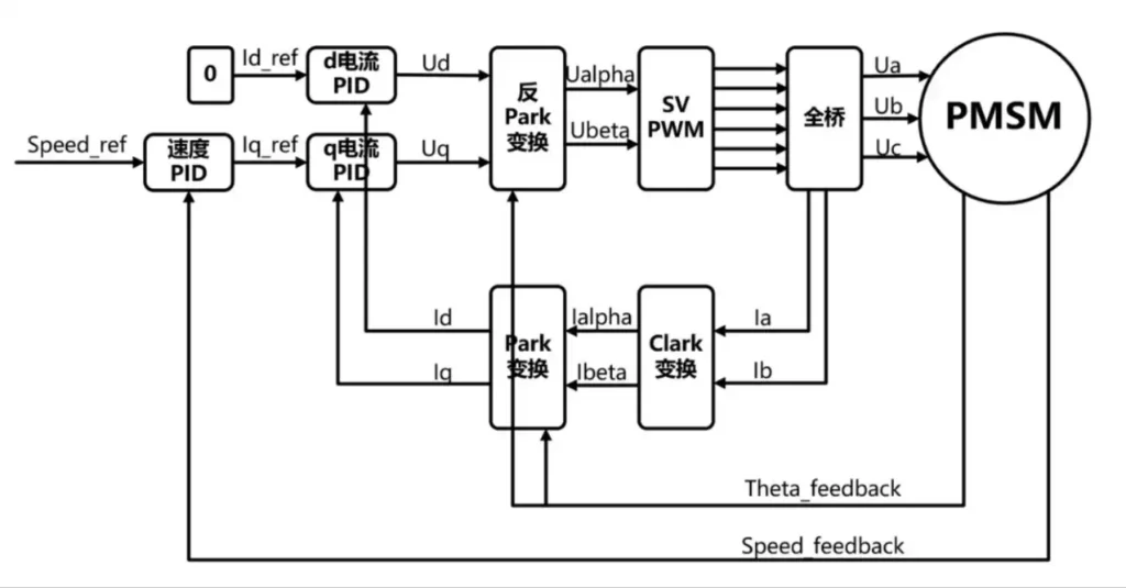
Field-Oriented Control (FOC)
FOC is one of the most advanced control strategies available. It decomposes the stator current into magnetizing and torque components, allowing for independent and precise control of torque and magnetic flux, similar to the control of a DC motor. FOC not only provides an extremely smooth torque output but also achieves the highest operating efficiency across the entire speed range.
The performance of a BLDC motor is not solely determined by its mechanical structure but is inextricably linked to the complexity and intelligence of its electronic controller. The choice of commutation strategy is a trade-off between cost, control complexity, and operational refinement. A system using basic Hall sensors and six-step trapezoidal control has a relatively simple and low-cost controller design.
However, this discrete, step-based commutation inevitably leads to torque ripple, which manifests as vibration and noise. Conversely, to achieve ultimate smoothness and quietness (e.g., in high-end home appliances or medical devices), advanced algorithms like FOC must be used.
This requires the controller to have a more powerful microprocessor, faster computational capabilities, and more precise current feedback circuits, which significantly increases the cost and design complexity of the controller. Therefore, the same motor, when paired with different levels of controllers, can offer a vastly different performance experience for the user. This highlights the critical role that software and electronic hardware play in defining the final product performance in a BLDC system.
What Is The Difference Between Brushed And Brushless Motor
To visually summarize these differences, the table below provides a comprehensive comparison:
| Feature | Brushed DC Motor | Brushless DC Motor (BLDC) |
| Commutation | Mechanical (brushes & commutator) | Electronic (external controller & sensors/algorithms) |
| Core Structure | Wound rotor (armature), permanent magnet stator | Permanent magnet rotor, wound stator |
| Efficiency | Medium (60% - 80%) | High (85% - 90%) |
| Lifespan | Limited (by brush wear, 2,000-5,000 hours) | Very long (by bearings, >10,000 hours) |
| Maintenance | Requires periodic brush replacement | Generally maintenance-free |
| Speed Limit | Limited by mechanical commutation, lower speed | Only limited by mechanical strength, can achieve very high speeds |
| Torque Characteristics | Good startup torque | High torque-to-weight ratio, flat torque over wide speed range |
| Audible Noise | Higher (mechanical friction & electrical sparks) | Very low (only bearing noise) |
| EMI | Significant (commutation sparks) | Very low (no sparks) |
| Heat Dissipation | Poor (heat source is in the internal rotor) | Excellent (heat source is in the external stator) |
| Control Complexity | Simple (direct DC voltage application) | Complex (requires an electronic controller) |
| Initial Cost | Low | High |
| TCO | Higher (due to maintenance and energy consumption) | Lower (due to long life, no maintenance, and high efficiency) |
If you want a more detailed comparison between brushed and brushless motors, you can click on the linked article to learn more. We will not elaborate on it here.
BLDC Motor Configuration Analysis: Inrunner vs. Outrunner
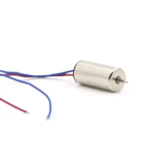
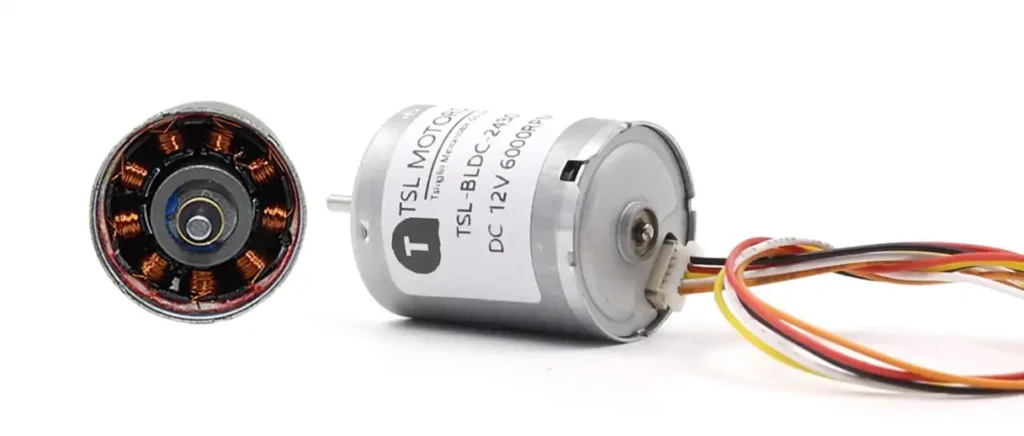
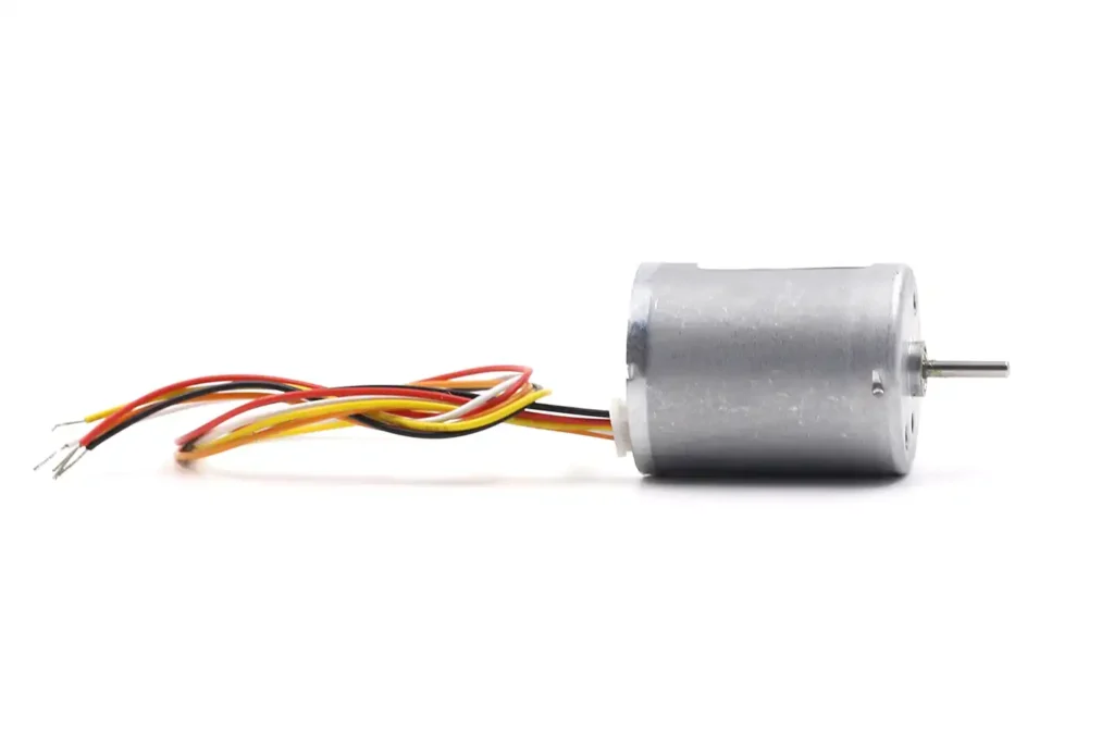
Inrunner Configuration: Built for Speed
Structure
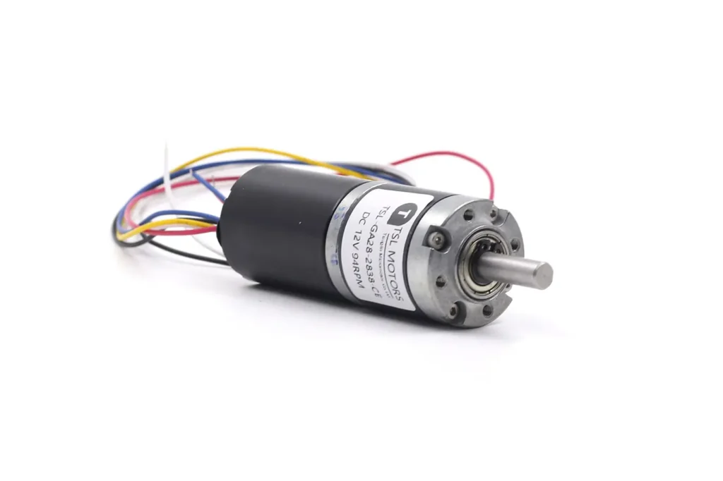
In the inrunner design, the rotor with permanent magnets is located in the center of the motor, while the stator windings are fixed to the inside of the casing, surrounding the rotor. Its appearance is similar to a traditional motor, with the casing being stationary and only the central output shaft rotating.
Performance
The core performance characteristic of inrunner motors comes from their slender, lightweight rotor. This type of rotor has a small diameter and low mass, thus having very low rotational inertia. Low inertia means the motor can accelerate or decelerate extremely quickly, is very responsive, and can reach extremely high speeds (RPM). Therefore, inrunner motors typically have a high Kv value (RPM per volt).
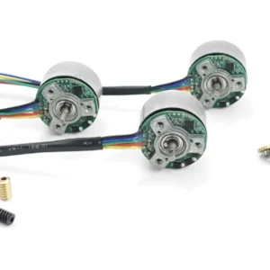
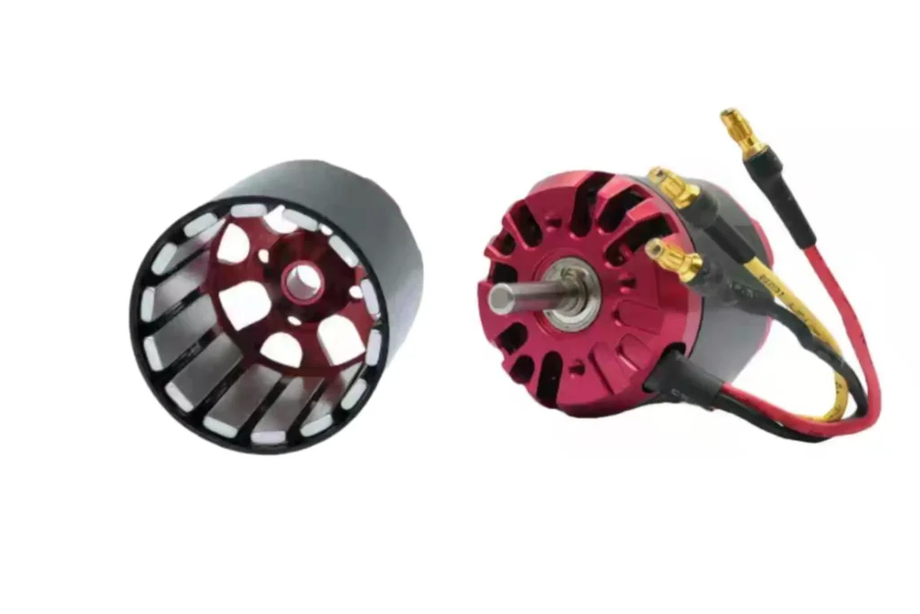
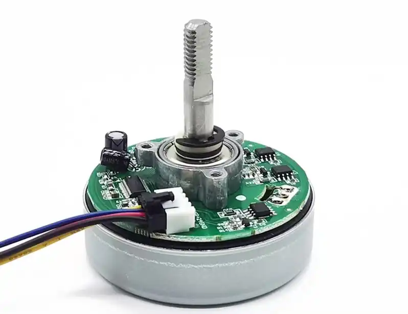
Outrunner Configuration: Built for Torque
Structure
The structure of the outrunner design is the opposite. The stator windings are fixed to the central shaft of the motor, while the rotor is a “cup” or “bell-shaped” structure with permanent magnets mounted on its inner wall. The entire rotor (along with the casing) rotates around the central stator. When operating, the entire motor casing rotates.
Performance
The biggest advantage of outrunner motors is their ability to output huge torque at lower speeds. The physics behind this is the lever effect: because the permanent magnets are placed at a larger radius farther from the center of rotation, the lever arm (radius) is longer. According to the formula
Torque = Force × Radius, a longer lever arm can generate greater torque for the same electromagnetic force. To further increase torque, outrunner motors are often designed with more magnetic pole pairs. Correspondingly, their Kv values are usually low.
The table below summarizes the core differences in design and performance between inrunner and outrunner BLDC motors.
| Feature | Inrunner | Outrunner |
| Rotor Position | In the center inside the stator | Outside the stator, surrounding it |
| Stator Position | Outside the rotor, fixed to the casing | Inside the rotor, fixed to the central shaft |
| Rotating Part | Central rotor and output shaft | Entire casing (bell) and output shaft |
| Torque Output | Lower | Very high |
| Speed (RPM) Capability | Extremely high | Low to medium |
| Kv Value | Typically higher | Typically lower |
| Rotational Inertia | Low, fast response | High, smooth operation |
| Heat Dissipation | Excellent (heat source is external, easy to dissipate) | Poor (heat source is internal, difficult to dissipate) |
| Typical Physical Shape | Long and thin (small diameter, long axial length) | Flat and wide (large diameter, short axial length) |
| Common Applications | High-speed spindles, ducted fans, servo systems, applications with gearboxes | Drone propellers, hub motors, electric skateboards, direct-drive applications |
Why Is A Brushless Motor Better
Based on the preceding analysis, BLDC motors demonstrate a series of decisive advantages over traditional motor technologies, making them the preferred, and in many cases the only, solution in numerous modern applications. These advantages include:
- High Efficiency: By eliminating brush friction losses, their energy conversion efficiency is extremely high (85-90%), which significantly saves energy and is especially important for battery-powered devices.
- Long Lifespan and High Reliability: With no mechanical wear parts, their lifespan far exceeds that of brushed motors, limited only by the bearings, which greatly reduces maintenance needs and failure rates.
- High Power Density and Torque-to-Weight Ratio: Superior heat dissipation and high-strength permanent magnet materials allow them to provide powerful output in a compact and lightweight package.
- Precise and Dynamic Control: When paired with an advanced electronic controller, they can achieve precise speed, torque, and position control over a wide range, with a quick response time.
- Quiet Operation and Low EMI: Without brush friction and electrical sparks, they operate extremely quietly and generate very low EMI, making them friendly to the environment and surrounding electronic devices.
These combined advantages make BLDC motors not just a simple technological replacement but a leap in performance.
Conclusion
BLDC motors have become a cornerstone technology for modern high-performance electromechanical systems due to their comprehensive superiority in efficiency, reliability, power density, and control precision.
Fundamentally, the design revolution that replaced the mechanical commutator with an intelligent electronic controller is the logical starting point for all of its technical advantages. This change not only eliminated the inherent defects of mechanical wear but also unlocked infinite possibilities for continuously optimizing motor performance through advanced algorithms.
The comparative analysis of the two main configurations—inrunner and outrunner—reveals the profound trade-off between design and performance: inrunners, with their low inertia and high speed, serve applications requiring fast dynamic response, while outrunners, with their high torque output, dominate the direct-drive field.
This design diversity further broadens the applicability of BLDC technology, allowing it to precisely match different needs, from high-speed precision equipment to high-torque power systems.
In a world increasingly pursuing electrification, automation, and intelligence, the core position of BLDC motors as an efficient, reliable, and controllable power source will only become more secure, and they will continue to serve as a key enabling technology, driving innovation and change across various industries.
FAQ
Q1:What is a brushless motor?
A1:A brushless motor has no physical brushes. It uses an electronic controller for precise current control, making it more efficient and durable than a traditional brushed motor.
Q2:What makes brushless motors better than brushed motors?
A2:With no brushes to wear out, brushless motors have a longer lifespan and are virtually maintenance-free. They are also more efficient, quieter, and produce less electromagnetic interference.
Q3:Why do some brushless motors have high speed and others have high torque?
A3:This is due to two different structural designs:
- Inrunner designs are built for high speed and fast response, suitable for applications needing high RPM (like fans, spindles).
- Outrunner designs provide high torque and are ideal for directly driving heavy loads (like drone propellers, electric skateboard wheels).
Q4:Why are brushless motors so important?
They are an “enabling technology.” Their high performance has made many new products (like drones and electric vehicles) possible, driving innovation and development across various industries.
Tsinglin Motor: Custom DC Motor Solutions
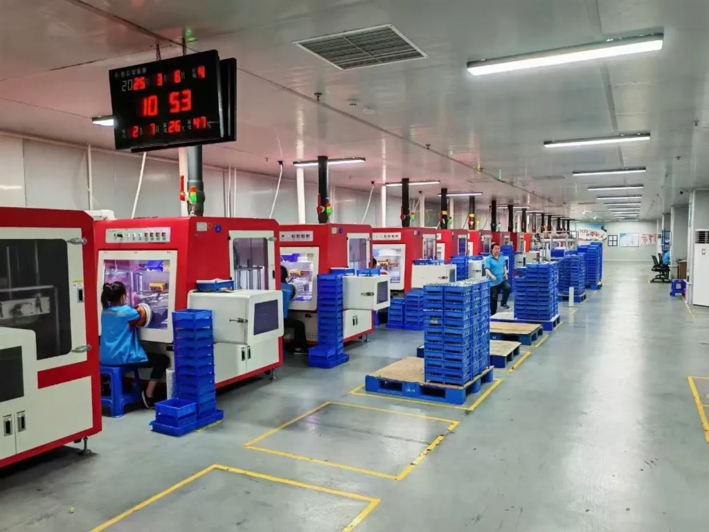
Established in 2009, Tsinglin Motor has evolved into a leading innovator in precision drive systems and specialized motor manufacturing. Our 15,000㎡ advanced production facility in Shenzhen houses a skilled workforce of 200+ professionals, delivering an annual output of 2 million units to global markets.
Continuous R&D investment in energy-efficient motor technologies
Lean manufacturing processes ensuring cost-competitive pricing
Agile production capacity scaling for batch customization
Global compliance certifications (CE, RoHS, REACH)
With dual focus on operational excellence and client success, Twin Motor empowers businesses worldwide to achieve technological differentiation. Our engineering team welcomes complex challenges across automotive, robotics, and smart infrastructure applications.
Contact our solutions center to discuss your project requirements or request our technical portfolio.
Tsinglin Motor’s Relevant Brushless DC Motor Series
-
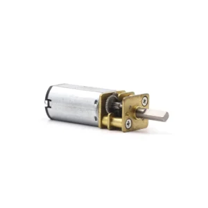
 Custom Micro Motors8 products
 - DC Gear Motor137 products
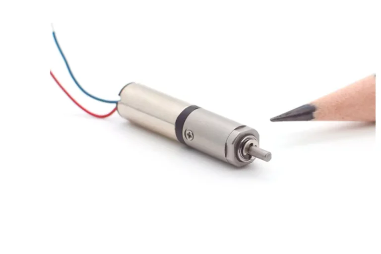
- 6mm Planetary Gear Motor4 products
- 6mm Planetary Metal Gear Motor3 products
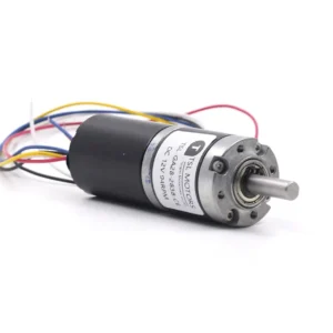
- Brushless Gear Motor17 products
- Micro Gear Motor62 products
- Coreless Gear Motor11 products
- N20 Gear Motor26 products
- Plastic Gearbox Motor8 products
- Standard Gear Motor15 products
- Stepper Gear Motor13 products
-
- Planetary Gear Motor29 products
- Spur Gear Motor63 products
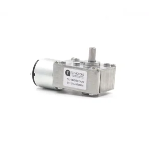
- Worm Gear Motor28 products
-
- DC Motor68 products
- Brushed DC Motor16 products
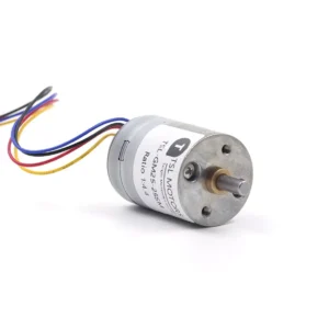
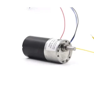
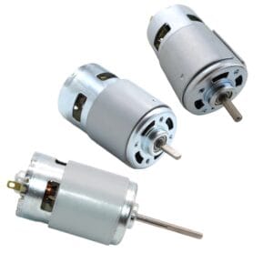
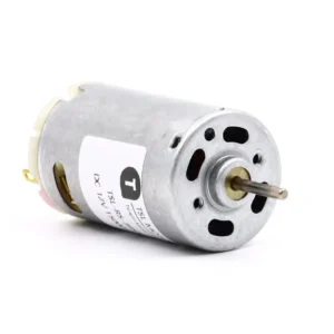
- Brushless DC Motor24 products
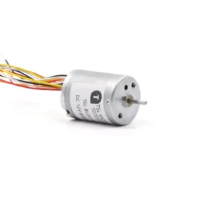
- Inrunner Rotor BLDC Motor6 products
- Outrunner Rotor BLDC Motor16 products
-
- Coreless DC Motor13 products
- Micro DC Motor15 products
-
- Stepper Motor22 products
- Micro Stepper Motor13 products
- NEMA Stepper Motor6 products
- Stepper Motor Linear Actuator4 products
-
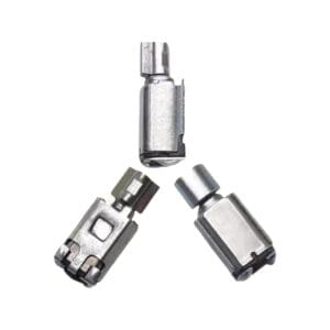
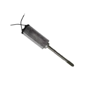
- Vibration Motors71 products
- Brushless Vibration Motor8 products
- Coin Vibration Motor22 products
- Coreless Vibration Motor3 products
- Encapsulated Vibration Motor6 products
- Linear Resonant Actuator12 products
- Powerful Vibrating Motor17 products
- SMD Vibration Motor4 products
- Sonic Vibration Motor2 products
-