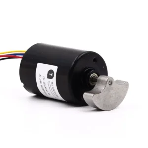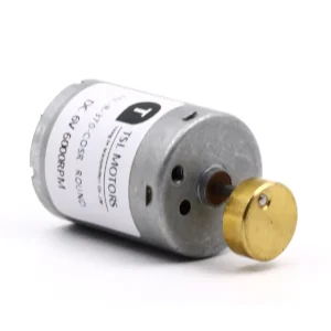
A brushless DC motor consists of a motor body and a driver, making it a typical mechatronic product. The stator windings are usually designed in a three-phase symmetric star configuration, similar to a three-phase induction motor.
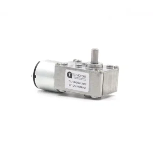
The rotor has permanently magnetized magnets attached to it, and position sensors are installed inside the motor to detect the polarity of the rotor. TSL brushless DC motors are widely used in home appliances, industrial automation, medical equipment, precision instruments, and electric tools.
Unlike brushed DC motors, brushless DC motors use electronic commutation. To rotate a brushless motor, the stator must be energized in a specific sequence. This requires knowing the exact position of the rotor. The rotor position is detected by Hall sensors embedded in the stator.
Key Takeaways
- Introduction to the Hall Effect.
- Working Principle of Hall Sensors.
- Components of a Hall Sensor.
- Hall Sensors in BLDC Motor Controllers.
- Sensor Placement and Adjustment.
- Rotor Position Detection.
- Feedback for Motor Control.
- Choose reliable brushless dc motor with controller manufacturers.
What Is a Hall Sensor?
Hall Effect
The Hall Effect occurs when a current-carrying conductor is placed in a magnetic field. The magnetic force causes the electric charges in the conductor to accumulate on one side.
This effect becomes more noticeable when the conductor is thin and flat. The charge buildup creates an opposing electric field that balances the magnetic force.
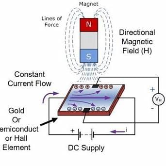
As a result, a voltage is generated across the two sides of the conductor. This voltage is known as the Hall voltage.
The phenomenon is called the Hall Effect, named after E.H. Hall, who discovered it in 1879.
How Hall sensors work to detect magnetic fields
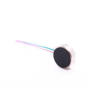
A Hall sensor is a device that uses the Hall Effect to measure the strength, direction, and polarity of a magnetic field.
It typically consists of a thin Hall element, a magnetic field, and a signal processing circuit.
When a magnetic field passes through the Hall element, the electrons inside experience the Lorentz force, causing them to move in a specific direction.
This movement leads to the accumulation of electrons, creating a voltage difference across the sides of the element.
The signal processing circuit detects this voltage difference and converts it into information about the magnetic field’s strength, direction, and polarity.
The circuit can then convert this data into either a digital or analog signal for further processing or display.
Tip:If you need a brushless DC motor with Hall sensors or a controller, we are an excellent choice. With over ten years of experience, feel free to contact us, and we will provide you with solutions that save you a significant amount of time.
How Hall Sensors Work in BLDC Motor Controllers
Placement of Hall sensors inside the motor
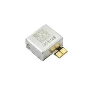
The Hall element is placed in a fixed position within the motor. Installing the Hall element on the stator can be more complex, as if it is not aligned correctly with the rotor’s magnetic field, the measurements may not be accurate.
To simplify the installation, redundant magnets are often placed on the rotor. These magnets are specifically designed to be sensed by the Hall element, ensuring it detects the rotor’s magnetic field.
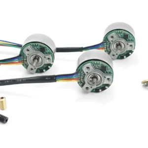
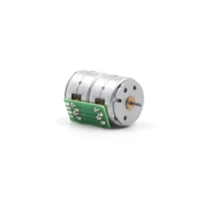
For ease of installation, Hall elements are often arranged in a circular pattern on a printed circuit board (PCB). These elements are equipped with an adjustable cover, allowing users to easily fine-tune their position according to the magnetic field direction for optimal performance.
Detect rotor position, send feedback
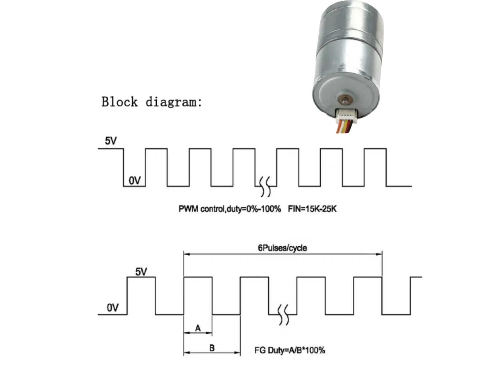
Three Hall sensors are typically placed around the rotor’s path.
As the rotor’s magnetic poles pass the Hall elements, each sensor outputs a high or low signal based on the polarity of the pole.
By analyzing the timing of the signals from the three sensors, the controller can determine the rotor’s position.
This information allows the controller to energize the stator windings accordingly.
Tip:If you need a brushless DC motor with Hall sensors or a controller, we are an excellent choice. With over ten years of experience, feel free to contact us, and we will provide you with solutions that save you a significant amount of time.
Summary
The Hall Effect occurs when a current-carrying conductor is placed in a magnetic field, causing charge accumulation on one side, creating a voltage difference. Hall sensors use this principle to measure the magnetic field’s strength, direction, and polarity.
A Hall sensor consists of a Hall element, a magnetic field, and a signal processing circuit. When the magnetic field passes through the Hall element, electrons experience the Lorentz force, creating a voltage difference, which is converted into a signal.
In BLDC motors, Hall sensors are placed around the rotor to detect its position. Three Hall sensors analyze signal timing, helping the controller determine the rotor’s position and energize the stator windings.
To simplify installation, redundant magnets are often placed on the rotor. Hall elements are typically arranged on a PCB, allowing easy adjustment for optimal performance.
Tip:If you need a brushless DC motor with Hall sensors or a controller, we are an excellent choice. With over ten years of experience, feel free to contact us, and we will provide you with solutions that save you a significant amount of time.
FAQ
Q:What is the voltage range and current range of the Hall element?
A:The voltage range of the Hall element is from 4V to 24V, and the current range is from 5mA to 15mA.
Q:What happens to the torque when the angle between two magnetic fields is 90°, and what occurs when the fields overlap?
A:Theoretically, a larger torque is generated when the angle between two magnetic fields is 90°. When the two magnetic fields overlap, the torque becomes zero.
Q:How are the windings powered during each commutation, and what happens to the third set of windings?
A:For each commutation, one set of windings is powered in the positive direction, the second set is powered in reverse, and the third set is not energized.
TSL-Motor: Custom Motor Solutions

At TSL, we transform your unique requirements into high-performance, reliable motor solutions. From concept to mass production, our engineering expertise ensures your devices stand out with durability and efficiency.
To Accelerate Your Project, Prepare These Details:
- Electrical Requirements: Operating voltage , Current consumption limits, Drive signal type , etc.
- Mechanical Constraints:Max dimensions,Mounting method,Shaft direction,etc.
- Performance Targets:Vibration force (G-level) at specific frequencies ,Start/stop response time ,Durability,etc.
- The timeline for this project and the annual consumption of motor products.
Our product range includes:
-
 Custom Micro Motors8 products
 - DC Gear Motor137 products
- 6mm Planetary Gear Motor4 products
- 6mm Planetary Metal Gear Motor3 products
- Brushless Gear Motor17 products
- Micro Gear Motor62 products
- Coreless Gear Motor11 products
- N20 Gear Motor26 products
- Plastic Gearbox Motor8 products
- Standard Gear Motor15 products
- Stepper Gear Motor13 products
-
- Planetary Gear Motor29 products
- Spur Gear Motor63 products
- Worm Gear Motor28 products
-
- DC Motor68 products
- Brushed DC Motor16 products
- Brushless DC Motor24 products
- Inrunner Rotor BLDC Motor6 products
- Outrunner Rotor BLDC Motor16 products
-
- Coreless DC Motor13 products
- Micro DC Motor15 products
-
- Stepper Motor18 products
- Micro Stepper Motor13 products
- NEMA Stepper Motor2 products
- Stepper Motor Linear Actuator4 products
-
- Vibration Motors71 products
- Brushless Vibration Motor8 products
- Coin Vibration Motor22 products
- Coreless Vibration Motor3 products
- Encapsulated Vibration Motor6 products
- Linear Resonant Actuator12 products
- Powerful Vibrating Motor17 products
- SMD Vibration Motor4 products
- Sonic Vibration Motor2 products
-