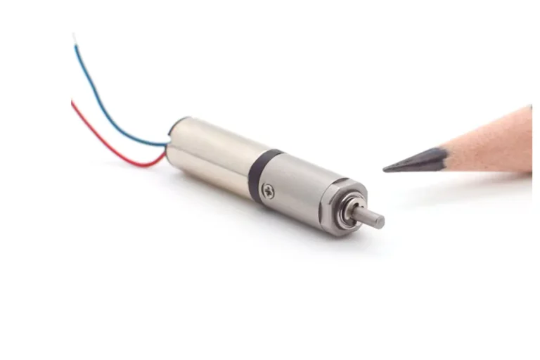
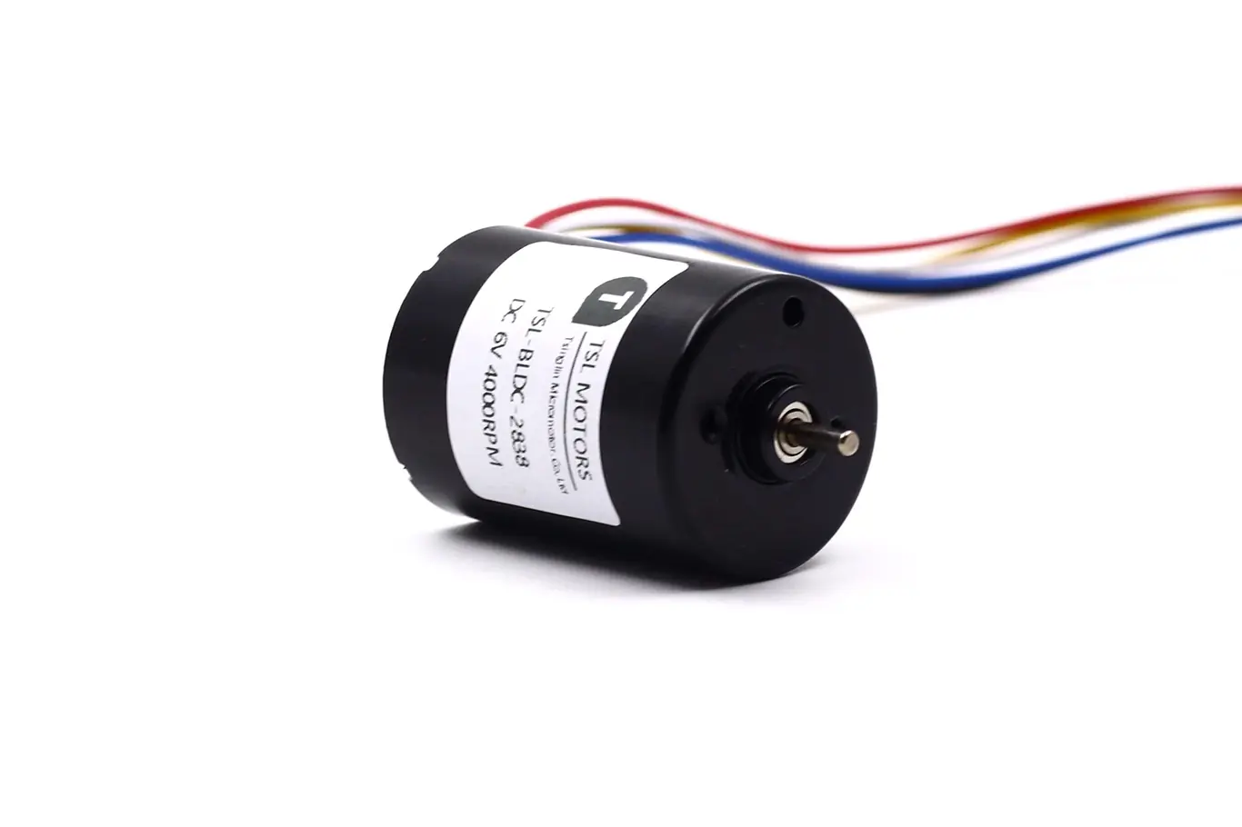
Inrunner brushless dc motors (BLDC) are widely used. Applications include robotics, medical devices, drones, precision pumps, high-speed fans, and small automation systems. This is due to their advantages: high-speed operation, fast response, efficient energy conversion, and compact size.
Among BLDC designs, the Inrunner brushless dc motor structure is unique: “inner rotor, outer stator.” This layout excels in rotational speed, heat dissipation, and operational stability.
TSL MOTOR, with over 15 years of experience, will deeply analyze the Inrunner BLDC motor. We will cover its structure, working principle, and core performance advantages.
This aims to help engineers, manufacturers, and procurement staff. The goal is a comprehensive understanding of its technical features and selection criteria. This ensures optimal performance and reliability in real-world applications.
Key Takeaways
- Structure and Thermal Advantage: The Inrunner features an inner rotor and an outer stator structure. The heat source is against the housing, ensuring superior heat dissipation and long-term stability.
- Speed and Response: The rotor has a small diameter, resulting in extremely low inertia. This allows the motor to achieve very high RPMs and fast dynamic response.
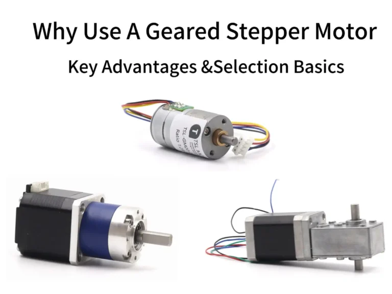
- Primary Limitation: Compared to Outrunners, its low-speed torque density is lower. A gearbox is often required in the system to compensate for this torque deficit.
- Core Drive Requirement: The motor must be driven by an Electronic Speed Controller (ESC). The ESC’s performance and parameter matching are key to unlocking the motor’s full potential.
- Typical Applications: The Inrunner is the expert solution for high speed and precision. It is widely used in robotic joints, high-speed fans, and medical precision instruments.
What are Inrunner Brushless DC Motors?
An Inrunner motor is a type of BLDC motor. Its characteristic feature is: the rotor is internal, and the stator is external. The opposing structure is the Outrunner motor. Its rotor is on the outside and rotates the outer casing.
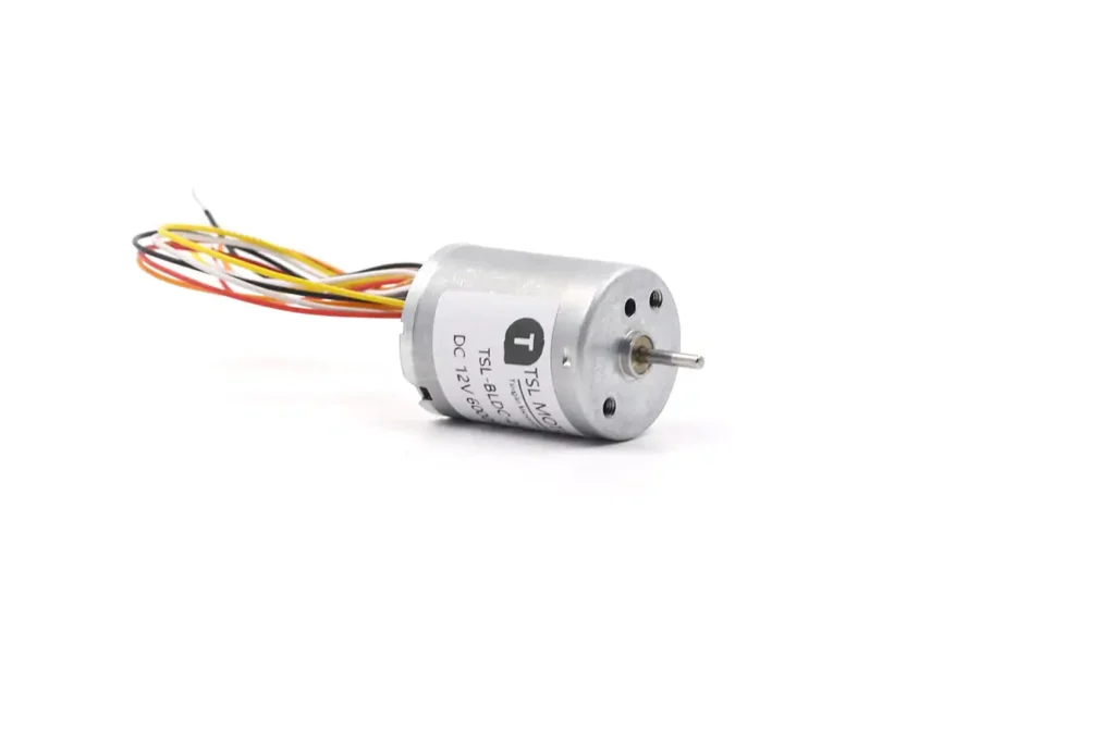
A complete Inrunner brushless dc motor typically consists of these key components:
Rotor
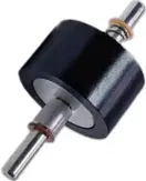
The rotor is the core moving part of the motor. It is usually made of NdFeB rare earth magnets, a metal shaft, and a rotor sleeve. The sleeve prevents the magnets from loosening or breaking at high speeds. The rotor’s small diameter results in lower rotational inertia. This means the motor can accelerate or brake in a very short time. It is highly suitable for high-speed applications.
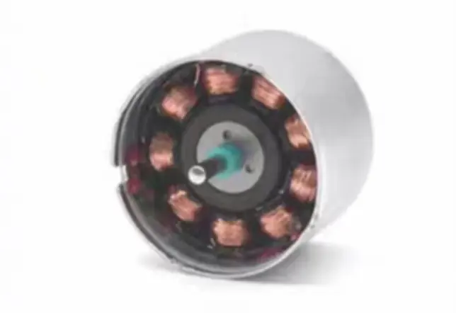
Stator

The stator is the motor’s “energy source.” It consists of stacked silicon steel laminations and three-phase copper coils. The coils generate a rotating magnetic field via the driver (ESC). This drives the rotor to rotate synchronously. The winding method (concentrated or distributed) directly affects the motor’s efficiency and torque characteristics.
Note that the stator is the motor’s main heat source. Therefore, heat dissipation paths must be considered during design.
Bearing System
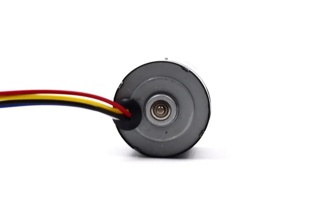
Bearings directly determine the motor’s lifespan and running quality. TSL MOTOR high-speed Inrunner motors typically use imported, high-precision Japanese bearings. This reduces friction and noise. Engineers must pay special attention to bearing lubrication and sealing. Ingress of dust or moisture will accelerate wear.
Housing & End Caps
The housing is more than just a protective shell. It also provides heat dissipation and electromagnetic shielding. Common materials are aluminum alloy or stainless steel. These ensure mechanical strength and fast heat conduction.
For medical or precision equipment, the housing must also minimize noise and vibration. Engineers often add heat sinks or air channels to the housing to improve cooling.
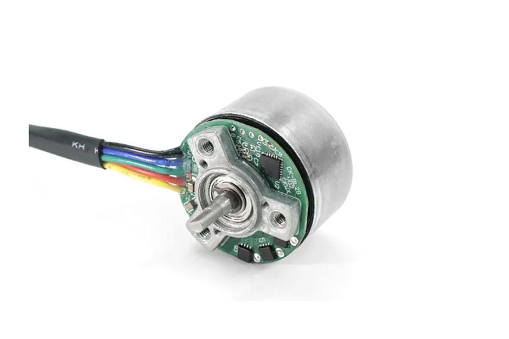
Hall Sensor
TSL MOTOR bldc motors have built-in hall sensors. These detect the rotor’s magnetic pole position in real-time. The signal is sent to the controller (ESC).

- Sensored Control: Relies on Hall sensors. Provides excellent starting performance and high stability at low speeds.
- Sensorless Control: Estimates rotor position by measuring the back-EMF (Back Electromotive Force). This reduces sensor cost and complexity. However, performance is slightly poorer at low speeds.
Application Selection: Engineers must decide on a sensored or sensorless solution based on the application scenario. For example, drones often use sensorless control. Medical devices prefer sensored control for precision.
How Inrunner Brushless DC Motors Work
The Inrunner brushless dc motor’s operation is a process of “electronic guidance and magnetic pursuit.” The electronic speed controller (ESC) continuously switches stator current based on rotor position. This generates a rotating magnetic field.
It pulls the permanent magnet rotor to rotate synchronously. This high-performance, high-reliability operation uses precise electronic control instead of mechanical brushes.
Driving Core: Electronic Speed Controller (ESC)
The biggest difference between BLDC and brushed motors is this: BLDC motors cannot run just by connecting them to a DC power source. They must rely on an Electronic Speed Controller (ESC) for driving. Think of the ESC as the motor’s “brain”:
- It receives external control signals (e.g., remote control throttle, industrial control system commands).
- It uses feedback from the rotor position sensors (Hall sensors or back-EMF detection).
- It precisely controls the switching sequence and current magnitude of the stator’s three-phase windings. This ensures smooth motor operation.
Without the ESC, the motor loses its nervous system—it has power but won’t move.
The core principle of the Inrunner brushless dc motor is electronic commutation. Simply put, it makes the stator generate a continuously rotating magnetic field. This field pulls the permanent magnets in the rotor to follow it.
Working Principle: Electronic Commutation
1.Initial Position Detection: The ESC needs to know the rotor’s magnetic pole position at startup.
- Sensored: Uses Hall sensors for direct detection.
- Sensorless: Estimates position via back-EMF.
- Example: North pole is detected facing Phase A winding.
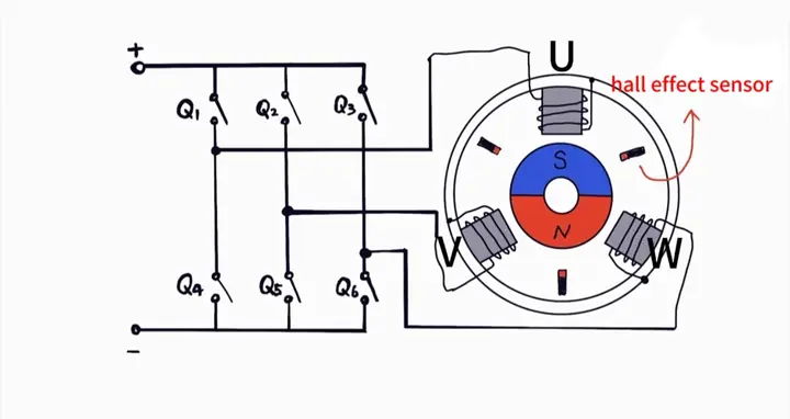
2.Stator Coil Energization: The ESC selects two windings to energize, leaving one de-energized, based on rotor position.
- Example: Phase U gets positive current, Phase V gets negative current, Phase W is off.
3.Magnetic Field Generation: The energized windings create an electromagnetic field.
- Example: Phase U creates a North pole, Phase V a South pole, creating a resultant magnetic field at an angle.
4.Magnetic Force Drive: The permanent magnets in the rotor are acted upon by mutual attraction and repulsion. This generates a rotational torque.
- The rotor begins to rotate.
5.Continuous Commutation: When the rotor moves to a new position, the Hall sensor gives immediate feedback.
- The ESC immediately switches the energization combination (e.g., from U+V- to U+W-).
- The stator magnetic field direction “moves forward.” It always stays ahead of the rotor, pulling it to continue rotating.
6.Cycle Repeats: The ESC completes the “detect position → switch phase sequence” process at a very high frequency (tens of thousands of times per second).
- Macroscopically, the stator magnetic field appears to rotate smoothly. The rotor maintains stable, continuous operation.
This process is called “commutation.” One complete electrical cycle involves 6 commutations.
Advantages of Inrunner Brushless DC Motor
Choosing an Inrunner brushless dc motor means high speed and high efficiency. Best for high‑speed fans, servo drives, propulsion systems. Advantages fully realized in these applications. Often the most competitive and reliable choice for engineers.
Extremely High Rotational Speed (High RPM)
The rotor (permanent magnet section) of an Inrunner brushless dc motor is internal. Its diameter can be very small. According to rotational mechanics, centrifugal force is proportional to the radius.
A small diameter means the rotor’s centrifugal stress is exponentially reduced at the same rotational speed. Therefore, higher ultimate speeds can be achieved.
This is why it is the core power for: RC race models, miniature gas turbines, dental handpieces, and certain centrifugal compressors. In these fields, rotational speed is a direct indicator of performance.
Excellent Heat Dissipation Capability
This is a frequently underestimated advantage of the Inrunner. The heat sources (stator copper and iron losses) are in direct contact with the motor housing. Engineers can easily design heat sinks, water-cooling jackets, or use tight connection to the equipment’s metal frame on the housing to dissipate heat.
Better heat dissipation means the Inrunner can operate at higher power for longer periods without power reduction due to overheating (thermal derating). Reliability is higher.
Low Rotational Inertia and Fast Response
Rotational inertia is the measure of an object’s resistance to changes in its rotational state. The smaller the inertia, the smaller the torque required to change its speed (accelerate or decelerate). The response is faster.
Inrunner brushless dc motors have mass concentrated at the center of rotation (small diameter). Their rotational inertia is much lower than Outrunner motors, which have mass distributed externally (large diameter).
This makes the Inrunner the preferred choice for servo systems, robot joints, and precision motion control platforms. In these applications, the motor requires frequent, precise starting, stopping, and speed changes. Fast dynamic response is key.
High Efficiency Range and High Power Density
BLDC motors are most efficient near their rated speed. The Inrunner’s inherently high-speed nature means its high-efficiency zone corresponds to high power output. For a given volume and weight, it can output higher mechanical power. Especially when paired with high-voltage drives, it can achieve high power with lower current. This further reduces copper losses and improves efficiency.
Therefore, the inrunner brushless dc motor is very suitable for equipment requiring continuous high-speed operation and energy efficiency. Examples include high-speed fans, centrifugal pumps, and electric vehicle main drives (most use the Inrunner design for high-speed cruising efficiency).
Low Noise and Low Vibration
TSL MOTOR DC motors use high-quality imported Japanese bearings, resulting in low mechanical noise. The engineering team optimizes stator slot and magnetic pole design. This greatly reduces cogging torque and torque ripple. It ensures extremely smooth electromagnetic operation.
For office equipment (e.g., high-speed scanners), medical instruments (e.g., MRI cooling pumps), and high-end audio equipment, quiet and smooth operation is a crucial user experience.
Limitations of Inrunner Brushless DC Motor
Lower Low-Speed Torque than Outrunner
Torque = Force × Radius. Small rotor → short radius → lower torque density. Even with optimized Kt, still less than Outrunner.
Solutions
- Add gearbox → more torque, but cost, loss, noise.
- Larger model → more torque, but bigger, heavier, expensive.
- Optimize Kt → stronger magnets, more pole pairs, higher slot fill. But efficiency drops.
Higher Cost
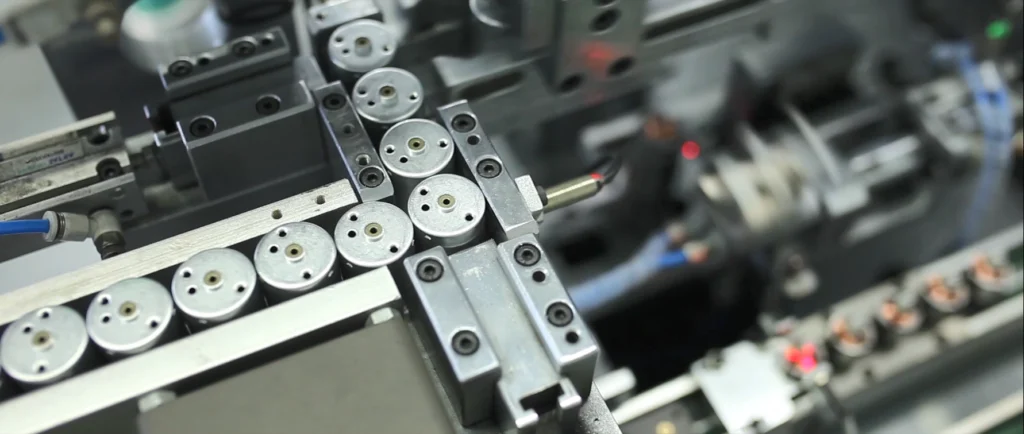
The Inrunner brushless dc motor requires stricter manufacturing processes to maintain stability at high speeds:
- High-precision Bearings: Must withstand tens of thousands of RPM while maintaining low noise and low friction.
- High-speed Dynamic Balancing: The rotor and stator must undergo strict dynamic balancing correction. Otherwise, vibration and noise will occur at high speeds.
Engineering Reality: These requirements make TSL MOTOR’s Inrunner manufacturing cost generally higher than Outrunner motors. This is especially true for small-batch customization or high-end applications.
High Dependency on Driver (ESC) Matching
The performance of the Inrunner is highly dependent on the ESC.
Key Parameter Matching:
- Current: The driver must provide sufficient peak current; otherwise, the motor cannot achieve maximum torque.
- Voltage: The motor’s rated voltage must match the driver’s output. Mismatch leads to overheating or insufficient performance.
- Commutation Method: Sensored (Hall sensor) or Sensorless (back-EMF) control methods are different. The driver must support the chosen method.
- Maximum Speed: The driver’s PWM frequency and control algorithm must keep up with the motor’s high-speed operation.
- Starting Method: At low-speed startup, the driver’s algorithm determines if the motor can start smoothly.
Engineer’s Experience: In high-speed applications, the driver’s performance is often more critical than the motor itself. An excellent ESC can unleash the motor’s full potential. A mismatched driver can lead to startup failure, jitter, overheating, or even burnout.
Inrunner Brushless DC Motor Typical Applications
The Inrunner brushless dc motor is an expert solution for “high speed” and “fast response” problems. When these needs are the primary constraints of the system, the Inrunner provides a performance ceiling that other motors struggle to reach, despite the system’s relative complexity.
Robot Joints & Actuators
The Inrunner brushless dc motor’s low inertia and fast high-speed response make it very suitable for robot joints and actuators.
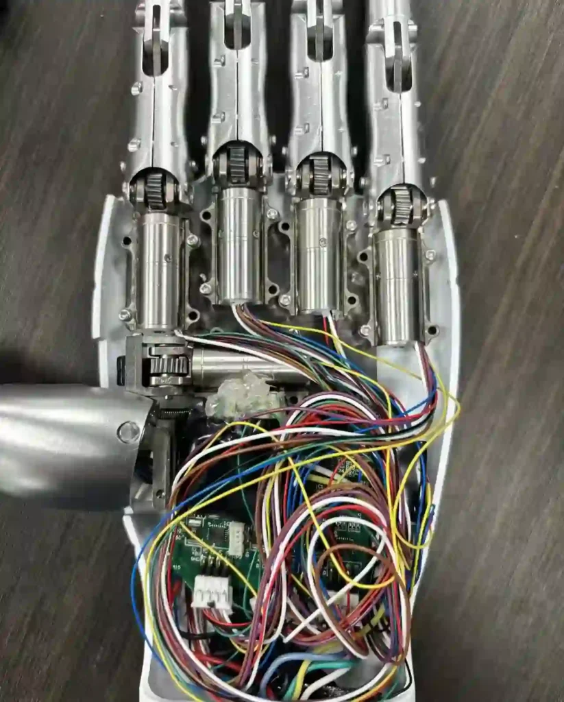
- Engineering Significance: In robot motion control, joints need to accelerate and brake quickly while maintaining precise positioning. The Inrunner’s small rotor diameter provides more sensitive speed control.
- Application Method: It is usually paired with a gearbox to compensate for insufficient low-speed torque. This preserves the fast response while delivering adequate torque.
Medical Equipment
In medical devices, reliability and quiet operation are primary requirements.
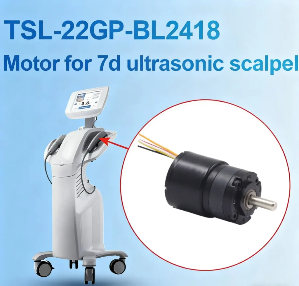
- Typical Applications: Handheld instruments, micro-pumps, nebulizers.
- Engineering Significance: The Inrunner’s external stator dissipates heat better, ensuring long-term stable operation. High-precision bearings and optimized magnetic circuit design allow it to maintain low noise and low vibration even at high speeds. This is ideal for medical environments.
Industrial Automation
In automation equipment, the motor needs to balance precision, stability, and compact design.
- Typical Applications: Automatic valves, precision feeding mechanisms, camera gimbals, small linear actuators.
- Engineering Significance: The Inrunner’s fast response and stable operation allow for precise control and long-term reliable work in these scenarios. The low inertia provides sensitivity, which is a key advantage, especially in gimbals and feeding mechanisms.
High-Speed Fans and Miniature Turbines
In high-speed fan and miniature turbine applications, high rotational speed is a hard requirement.
- Engineering Significance: The Inrunner motor’s structure is naturally suited for high-speed rotation. The small rotor and low inertia maintain stability at extremely high speeds.
- Advantage: The external stator provides a short heat dissipation path. This ensures long-duration, high-load operation without easily overheating.
Key Selection Points for Inrunner Brushless Motors
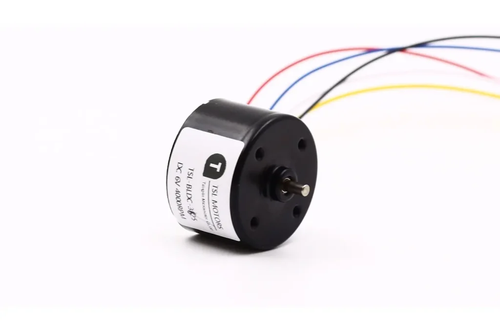
Operating Voltage (12V / 24V / Custom)
The motor’s rated voltage determines the design of the driver and power system. Common 12V and 24V systems suit small devices. Custom voltages are often used for special scenarios (e.g., medical or industrial equipment). Engineers must consider power architecture compatibility during selection. Also, consider the impact of voltage on efficiency and heat.
Optimization Principle: At the same power, higher voltage means lower current. This reduces line losses and driver heat, improving system efficiency. If space and cost allow, prioritize a higher voltage platform to optimize efficiency and performance.
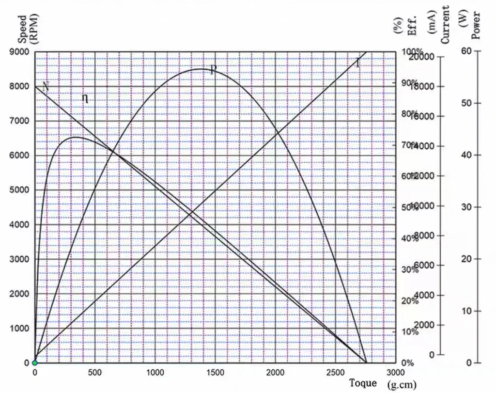
Target Rotational Speed
No-load Speed: The theoretical maximum speed of the motor without load.
Working Speed: The actual operating speed under load. Must be lower than the no-load speed.
Continuous / Peak Torque Requirements
The motor’s torque capacity must match the load demand.
- Continuous Torque: Determines if the motor can run stably for a long time.
- Peak Torque: Determines if the motor can handle transient loads (e.g., starting or accelerating).
Locked-Rotor Current and Driver Matching
- Locked-Rotor Current (I_stall): The current when the motor rotor is stalled (I_stall = Voltage / Phase Resistance). This is the system’s maximum potential current.
Driver Selection Golden Rule:
- Driver’s continuous output current > Motor’s continuous operating current.
- Driver’s peak output current > Motor’s peak current, and preferably > Motor’s locked-rotor current. This is crucial for preventing the driver from burning out during abnormal situations (e.g., emergency braking, load stalling).
- The driver’s input/output capacitors and MOSFET specifications must withstand the corresponding current surge. Always assess the actual operating conditions and avoid focusing only on rated parameters while neglecting peak demand.
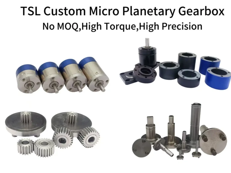
Need for a Gearbox
Due to the Inrunner’s insufficient low-speed torque, many applications require a gearbox for compensation.
- Pros: Increases torque, improves low-speed performance.
- Cons: Increases volume, weight, and cost. It also introduces efficiency loss and backlash issues.
Engineers must balance system efficiency and precision to decide whether to use a gearbox.
Starting Characteristics
The load type dictates the starting method:
- Light Load Start (e.g., Fan): Sensorless start can be used; low cost.
- Heavy Load Start (e.g., Loaded Conveyor Belt): Must use sensored start (Hall or encoder). This ensures sufficient starting torque without jitter or loss of step.
- Precise Positioning Start: Must use closed-loop start with an encoder.
In servo or precision control scenarios, starting characteristics must be a key verification point.
Permissible Temperature Rise and Heat Dissipation Conditions
The winding is the main heat source. The external stator aids heat dissipation, but still focus on:
- Permissible temperature rise range (usually 80-120°C).
- Heat dissipation conditions (air cooling, liquid cooling, housing heat conduction).
Engineers must confirm the motor’s thermal stability during continuous operation through actual temperature measurements.
Working Environment
- Protection Rating (IP Code):
- IP54: Dust protected, splash proof. Suitable for most industrial environments.
- IP67/IP68: Completely dustproof, can be temporarily submerged. Suitable for outdoor, cleaning, or underwater equipment.
- Special Environments:
- High Temperature: Requires H-class (180°C) or higher insulation materials and high-temperature magnets.
- Corrosive: Housing material needs to be stainless steel or surface treated.
- Clean/Vacuum: Requires non-magnetic, low outgassing materials (e.g., coreless cup motors).
Inrunner Brushless DC Motor Engineering Prevention Guide
Despite the Inrunner BLDC motor’s advantages (high speed, compact structure, short heat path), common issues still arise in real-world engineering and user feedback. The following is based on TSL MOTOR customer feedback and on-site engineer summaries. It helps in avoiding common pitfalls during selection and integration.
Starting Difficulties / Intermittent Failure to Start
Many engineers debugging sensored Inrunners experience this: the motor won’t spin after power-up, requiring a power cycle to recover.
Common Causes:
- Hall sensor installation angle offset or drift, causing inaccurate commutation points.
- Instantaneous voltage drop or insufficient current from the power supply.
- Mismatched driver startup parameters (start mode, timing).
Engineering Advice:
- TSL MOTOR’s built-in Hall sensors greatly mitigate the first cause.
- Ensure the power supply provides sufficient starting current.
- Optimize the starting mode and advance timing in the ESC.
- For systems with frequent start/stop cycles, prioritize a sensored Inrunner.
Unstable Low-Speed Operation, Jitter (Cogging / Stuttering)
Motor jitter at low speeds (crawling) is a common issue in robotics or RC scenarios.
Technical Roots:
- Sensorless drive back-EMF is too weak at low speeds; position estimation is inaccurate.
- Commutation errors cause oscillation.
- ESC parameters are not optimized for the Inrunner’s number of poles.
Engineering Advice:
- For applications requiring high low-speed control, definitely choose a sensored Inrunner.
- Adjust the ESC’s starting current, PWM, timing, and pole number parameters.
- Avoid using pure sensorless control in heavy-load starting scenarios (robotic arms, tracked robots, automatic doors).
Overheating / Insufficient Heat Dissipation During Long Runs
Although the Inrunner’s stator is close to the housing (theoretically better heat dissipation), the motor can still heat up significantly in sealed cavities or under high load.
Risks:
- Winding insulation aging, shortened lifespan.
- Magnet temperature too high, leading to demagnetization.
- Glue aging, causing magnet loosening or even shattering.
Engineering Advice:
- For TSL MOTOR’s customized high-speed or high-frequency applications, design air channels or heat sinks.
Bearing Wear, Vibration, Mechanical Noise
Bearing noise or efficiency drop after several months is common in drone or robotic equipment.
Causes:
- High-speed rotation leads to heavy bearing load.
- External impact, dust, or moisture ingress, causing lubrication failure.
- Installation coaxiality error, resulting in abnormal stress on the bearings.
Engineering Advice:
- Use sealed bearings in dusty or outdoor environments.
- Ensure coaxiality between the motor and load during installation to avoid side stress.
ESC / Driver Compatibility Issues
Some customers find motor performance suddenly improves after replacing the ESC. This shows that driver matching is crucial.
Common Problems:
- ESC does not match the motor’s pole count.
- Control algorithm is unsuitable for the Inrunner’s back-EMF characteristics.
- Driver power margin is insufficient.
Engineering Advice:
- Select an ESC that explicitly supports Inrunner / sensored motors.
- Verify the pole number parameter matches the motor.
- Reserve 30–50% power redundancy for the current.
Engineering Summary: How to Avoid Common Problems?
From an engineering perspective, the key to prevention is:
- Prioritize sensored Inrunners in critical control applications.
- Pair with an adapted ESC and correctly set pole number, timing, and starting parameters.
- Ensure mechanical installation coaxiality to reduce extraneous torque.
- Pay attention to heat dissipation design to avoid prolonged full-load operation at high temperatures.
- For high-speed applications, regularly inspect bearing and magnet status.
Conclusion
The Inrunner brushless dc motor offers unique advantages in robotics, medical devices, drones, and industrial automation. This is due to its fast response, excellent heat dissipation, compact structure, and high power density.
Its design logic makes it irreplaceable in high-speed and precision control scenarios. However, it comes with engineering challenges: insufficient low-speed torque, higher manufacturing cost, and high dependency on driver matching.
For engineers and equipment manufacturers, the key is to:
- View the motor and the suitable ESC driver as an integrated system.
- Consider heat dissipation, bearing life, and environmental adaptability in the design.
- Reasonably select sensored or sensorless control based on the application, and use a gearbox when necessary.
In short, the Inrunner brushless dc motor is a high-speed and high-efficiency solution. To unlock its full potential, a systematic approach to selection, driver matching, and thermal design is essential.
FAQ
Q1: What is the defining structural characteristic of an Inrunner BLDC motor?
A1: The rotor is located internally, and the stator is fixed externally (Inner Rotor, Outer Stator).
Q2: What are the three primary performance advantages of Inrunners?
A2: High rotational speed, fast dynamic response, and superior heat dissipation.
Q3: Why does the Inrunner structure offer better heat dissipation?
A3: The main heat source (the stator windings) is directly on the outer housing, allowing heat to escape quickly.
Q4: What is the main drawback of the Inrunner motor?
A4: Lower low-speed torque compared to an Outrunner of the same size.
Q5: Why are Inrunners preferred for precision motion control and robotics?
A5: Their small rotor diameter results in low rotational inertia, enabling fast acceleration and braking.
Q6: What essential component is required to operate a BLDC motor?
A6: An Electronic Speed Controller (ESC) to perform electronic commutation.
Q7: What is the difference between Sensored and Sensorless control?
A7: Sensored uses Hall sensors for precise position feedback (better low speed). Sensorless estimates position using Back-EMF (lower cost).
Tsinglin Motor: Custom DC Motor Solutions
Established in 2009, Tsinglin Motor has evolved into a leading innovator in precision drive systems and specialized motor manufacturing. Our 15,000㎡ advanced production facility in Shenzhen houses a skilled workforce of 200+ professionals, delivering an annual output of 2 million units to global markets.
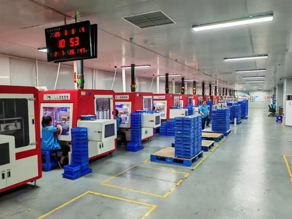
Continuous R&D investment in energy-efficient motor technologies
Lean manufacturing processes ensuring cost-competitive pricing
Agile production capacity scaling for batch customization
Global compliance certifications (CE, RoHS, REACH)
With dual focus on operational excellence and client success, Twin Motor empowers businesses worldwide to achieve technological differentiation. Our engineering team welcomes complex challenges across automotive, robotics, and smart infrastructure applications.
Contact our solutions center to discuss your project requirements or request our technical portfolio.
Brushless DC Motor
Brushless DC motors provide a solution to meet the demands for higher energy efficiency, longer lifespan, and quieter operation. As a leading manufacturer of BLDC motors,TSL Motors has developed the smallest BLDC motor, measuring just 6mm in diameter and 2mm in thickness, designed as a flat vibration motor.