In the world of mechanical transmission, what’s the smartest, most cost‑effective way to transform the high speed of an electric motor into powerful output torque? The answer is clear: the Spur Gear Motor.
Far from being a relic of the past, this classic drive solution is thriving in today’s era of smart manufacturing. From precision medical devices to rugged industrial conveyors, spur gear motors are everywhere — delivering efficiency, reliability, and unbeatable value.
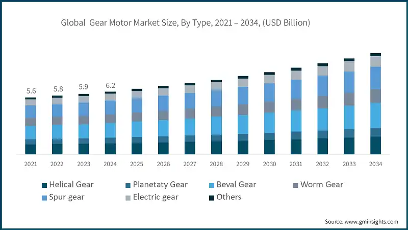
And the numbers speak for themselves. According to the gminsights, the global geared motor industry is projected to surpass $10 billion by 2034, with a steady 5% CAGR. At the heart of this growth lies the spur gear motor, prized for its unmatched balance of cost‑efficiency and transmission performance.
As one of China’s leading DC geared motor manufacturers, we understand the challenges engineers face when choosing the right power solution.
Whether you need standard specifications or tailor‑made designs, we provide a complete one‑stop service — from design and manufacturing to after‑sales support. This guide will walk you through the unique value of spur gear motors, helping you make the smartest choice for your next project.
key Takeaways
- Core Function: Achieves “Speed Reduction, Torque Multiplication,” converting high-speed, low-torque input into the low-speed, high-torque output required by machines.
- Primary Advantages: Most cost-effective, and boasts extremely high transmission efficiency (95%+ per stage), making it easy to integrate.
- Major Drawbacks: High noise (the most significant fault), lower relative load capacity, and moderate backlash (limiting precision).
- Competitive Edge: It is cheaper than Planetary motors; and is more efficient than Worm Gear motors, while also offering back-drivability.
- Structural Types: Available in Cylindrical, Flat/Square (Box Type, widely used in vending machines), and N20 Miniature forms.
- Typical Applications: Heavily used in vending machines, micro-robotics, light industrial conveyors, and certain medical devices.
- Selection Principle: Must determine the required continuous rated torque (Treq) and ensure the operating torque is far below the Stall Torque (recommended <30%) for a safety margin.
- Failure Modes: Common faults include tooth wear, breakage, and stripping of the gear teeth (often the first plastic stage under overload).
- Maintenance Point: Synthetic grease (silicone/PTFE-based) is mandatory for plastic gears; using high-viscosity damping grease is the primary method for noise reduction.
What is a Spur Gear Motor?
Definition
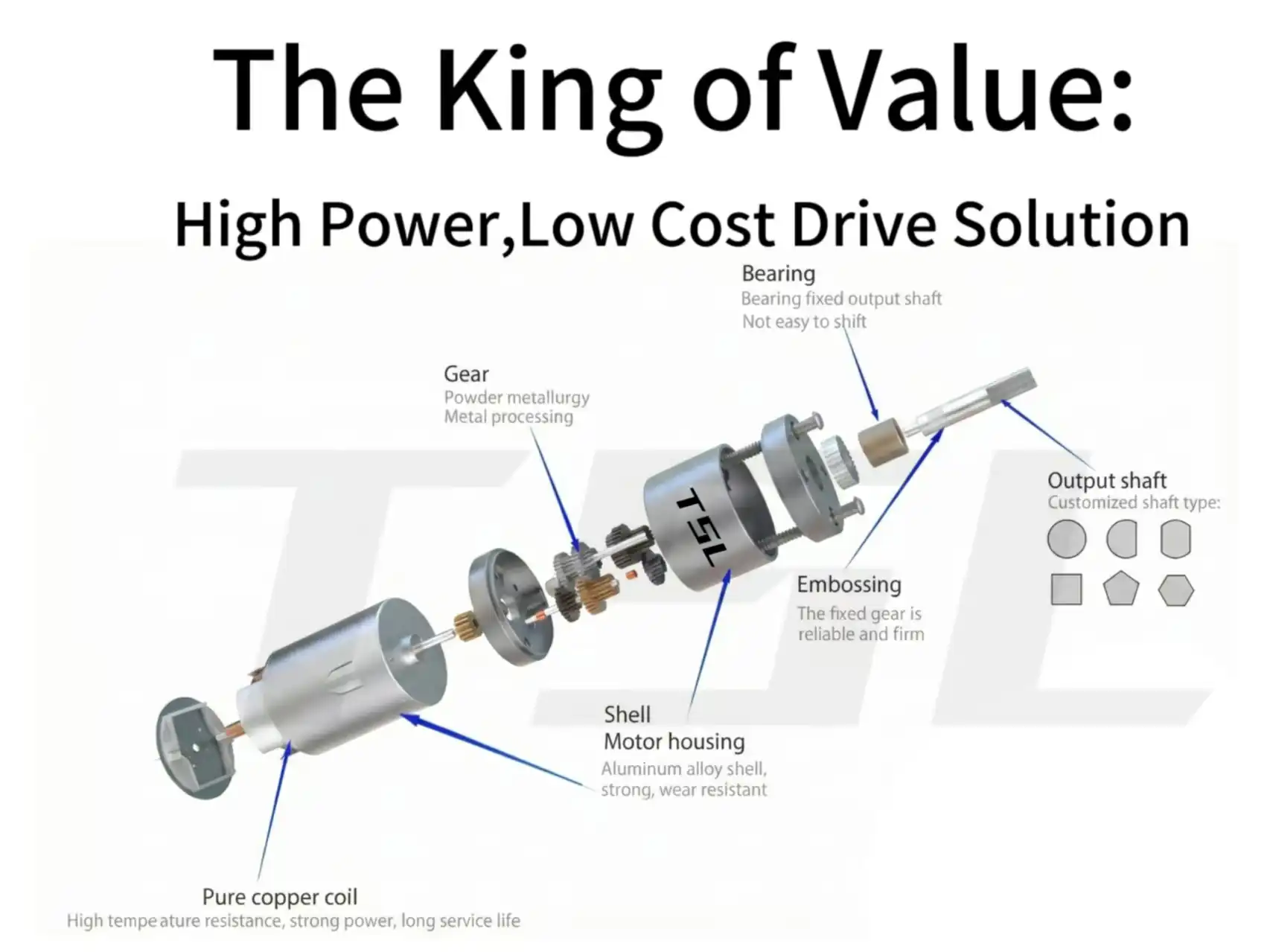
A Spur Gear Motor is an integrated electromechanical assembly that combines a DC motor with a spur gear reduction gearbox.
- Spur Gear: This is the simplest and most common gear type. Its teeth are straight and run parallel to the gear’s axis of rotation.
- Function of the Gearbox: Motors typically run at high speeds (e.g., several thousand RPM) but produce low output torque. The gearbox uses a set of gears to reduce the speed while simultaneously multiplying the output torque.
The gearbox acts as both a reducer and a torque multiplier. Miniature DC motors are usually most efficient when running at speeds between 3,000 to 10,000 RPM or higher.
However, most direct physical tasks—lifting loads, turning valves, or driving wheels—require significantly lower speeds and much more torque than the motor can produce directly. The spur gearbox mediates this mismatch, converting a high-speed, low-torque input into a low-speed, high-torque output.
How It Works
The core of a spur gear motor is a high‑speed DC motor. When energized, the rotor spins very fast, often thousands or even tens of thousands of RPM. This high speed comes with low torque.
The motor struggles to drive mechanical structures that need significant force or resistance. If connected directly to a load, it may fail to start. It can also drop speed quickly due to insufficient torque.
To make the small motor more powerful, speed must be reduced. Torque must be multiplied through a gear system.
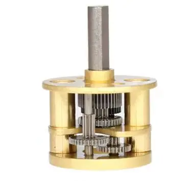
The spur gearbox uses small gears to drive larger gears. A pinion on the motor shaft meshes with a bigger gear. This completes the first stage of speed reduction and torque increase. The larger gear then drives another small pinion. That pinion meshes with an even larger gear.
This creates two, three, or even four stages of transmission. Each stage lowers speed and boosts torque. For example, three stages at 1:4 ratio give 1:64 reduction. This cuts speed while increasing torque dozens of times. The spur gear design is simple and efficient. It is the most common type in light‑duty gearboxes.
After passing through the gears, the motor’s power is reshaped. The output shaft delivers stable, usable speed and torque. Now the motor can move heavier loads. It can overcome greater resistance. It can maintain stronger control during operation.
Because of their simple design, spur gear motors are low‑cost. They are easy to maintain. They are widely used in automation equipment, small appliances, toys, smart locks, pumps, and light robots. They are the most economical reduction solution.
Types Of Spur Gear Motor
Spur gear motors can be categorized in several ways depending on their construction, torque requirements, and application environment. Below are the main types most commonly used in industrial, commercial, and consumer products.
By Gear Material
The choice of material is the most important determinant of the motor’s load capacity, noise characteristics, lifespan, and environmental suitability. They can be classified into plastic spur gear motors and metal spur gear motors.
1.Plastic Spur Gear Motors
Plastic gears revolutionized the miniature motor industry, enabling the miniaturization of devices in consumer electronics and medical technology.
Advantages:
- Lightweight: Ideal for portable devices, reducing overall weight.
- Low Noise: Plastic gears absorb some vibration during meshing, reducing operational sound.
- Cost-Effective: Efficient for mass production through injection molding.
Limitations:
- Limited load capacity; prone to deformation under high load or high temperature.
- Shorter lifespan; not suitable for continuous heavy-duty work.
Typical Applications:
- Toy motors (electric cars, robots)
- Small appliances (electric toothbrushes, blenders, coffee makers)
- Consumer electronics (printers, optical drives, internal camera drives)
Advantages:
- High Strength: Can withstand greater torque and shock loads.
- Wear Resistance: Suitable for long-term continuous operation, reducing maintenance frequency.
- Long Lifespan: Can operate stably for many years in industrial environments.
Limitations:
- Higher cost; complex manufacturing process.
- Noisier than plastic gears; requires lubrication and precision machining to mitigate.
Typical Applications:
- Industrial automation (conveyors, robotic arms, packaging equipment)
- Precision instruments (medical equipment, measuring instruments)
- High-torque applications (power tools, locks, electric pumps)
2.Metal Spur Gear Motors (Brass / Steel)
Metal gears are the industry standard for applications requiring high torque, impact resistance, and long service life. Brass gears offer good corrosion resistance, while steel gears provide superior strength and wear resistance.
By Motor Type
1.DC Brushed Spur Gear Motors
Working Principle::Current switching is achieved through carbon brushes and a commutator, driving the motor’s rotation.
- Pros:
- Low cost, simple control.
- Mature technology, easy to maintain.
- Cons:
- Limited lifespan due to carbon brush wear.
- Higher electrical noise.
- Typical Applications:
- Vending machines, actuators
- Home appliances (fans, blenders)
- Office equipment (printers, copiers)
Pros:
- High efficiency, low energy consumption.
- Long lifespan, minimal maintenance.
- Low electrical noise, suitable for precision equipment.
Cons:
- Higher cost.
- Complex control system.
Typical Applications:
- Medical devices (infusion pumps, surgical instruments)
- Smart locks, security systems
- Robotics and industrial automation
2.DC Brushless (BLDC) Spur Gear Motors
Working Principle: Current is controlled by an electronic commutator, eliminating the need for carbon brushes.
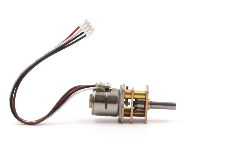
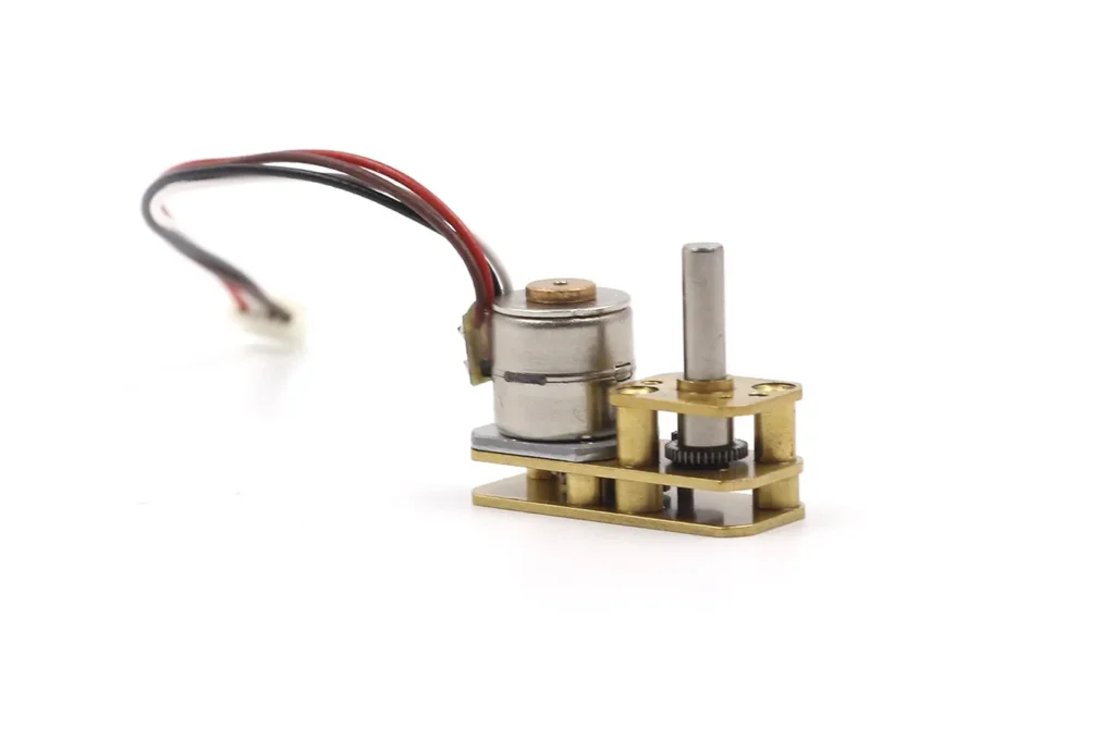
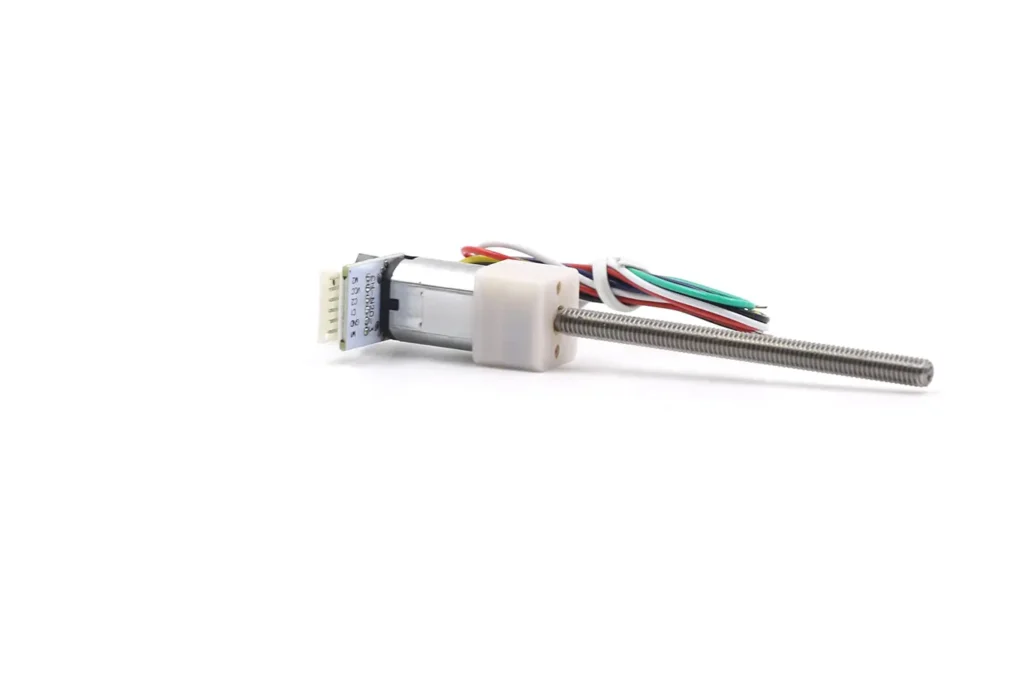
3.Stepper Spur Gear Motors

Working Principle: Driven by step pulses, the motor achieves precise angle control after gear reduction.
- Pros:
- High precision, capable of open-loop positioning.
- Simple control, suitable for low-speed, high-precision applications.
- Cons:
- Limited torque, lower efficiency.
- Prone to losing steps at high speeds.
- Typical Applications:
- Printers, scanners
- Camera lens focusing
- Small positioning systems, metering equipment
Pros:
- High efficiency, suitable for battery-powered devices.
- Fast response, suitable for dynamic control.
- Low noise, low vibration, smooth operation.
Cons:
- High cost.
- Limited load capacity, not suitable for heavy loads.
Typical Applications:
- High-end medical devices (micropumps, surgical robots)
- Precision instruments (optical equipment, laboratory automation)
- Consumer electronics (high-end cameras, smart wearables)
- Aeromodeling and drones
4.Coreless Spur Gear Motors
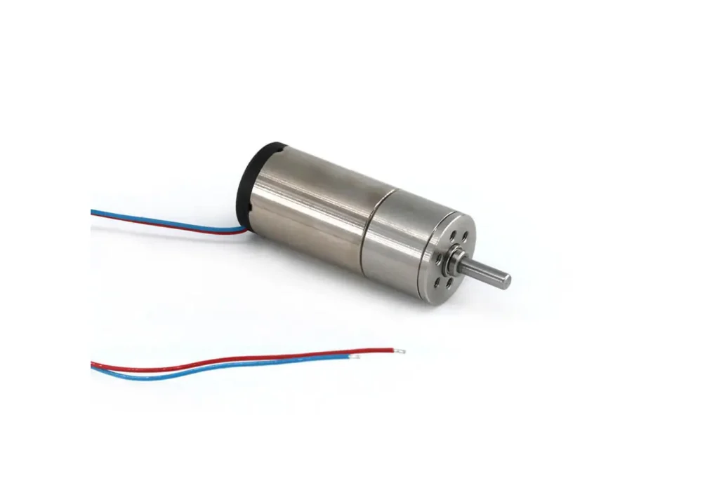
Working Principle: Uses a coreless rotor motor (hollow cup), resulting in extremely low inertia and fast response speed.
By Output Configuration
The internal arrangement of the gears determines the relationship between the motor axis and the output axis.
1.Inline Spur Gear Motor
Motor shaft and output shaft are on the same axis (coaxial).
Advantages:
- Simple structure, easy to manufacture
- High efficiency, low friction loss
- Easy to integrate, compact volume
Limitations:
- Strict requirements for installation space, less flexible layout
- Not suitable for special structural needs
Applications:
- Small robots
- Clocks
- Gear pumps
- Compact instrument equipment
Advantages:
- Provides more flexible layout options
- Suitable for special installation spaces
Limitations:
- More complex design and assembly
- May occupy more space than the inline type
Applications:
- Custom-cased equipment
- Side-mounted drive systems
- Automation requiring offset transmission
2.Offset Spur Gear Motor
Gear system shifts the output shaft to one side of the motor shaft (parallel but not collinear).
3.Foldback Spur Gear Motor
Gear set “folds back” above the motor body, shortening the overall length.
Advantages:
- Space-saving, suitable for length-constrained designs
- Maintains high efficiency and stable transmission of spur gears
- Lightweight, easy for compact integration
- Stable gear ratio, reliable transmission
Limitations:
- More complex internal structure, higher maintenance difficulty
- Slightly higher cost than inline and offset types
- Limited torque capacity compared to planetary or worm gears
- High assembly precision required; slight deviation can cause noise or wear
Applications:
- Micro-robot chassis (extremely compact spaces)
- Embedded systems (limited motor length)
- Portable instruments, handheld devices
- Micro-automation equipment (e.g., slides, micro-actuators)
- Dynamic art installations or applications requiring aesthetic structure
By External Structure (Form Factor)
The physical shape of the gearbox determines where the motor can be mounted within a machine.
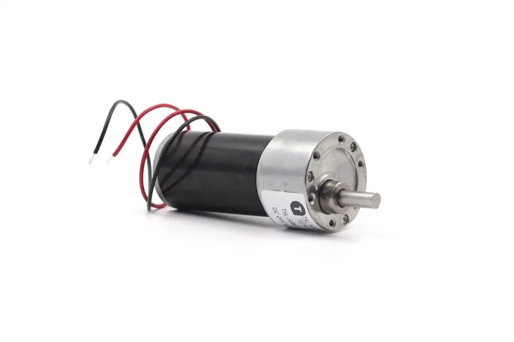
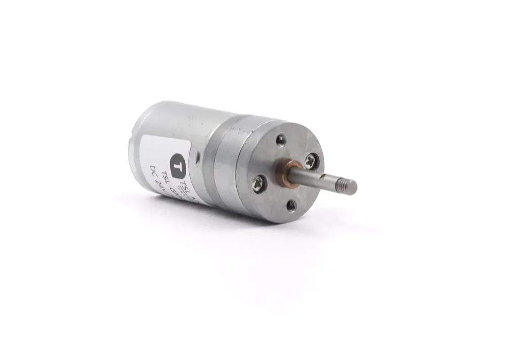
Design: The gearbox diameter usually matches the motor diameter standard (e.g., 12mm, 16mm, 25mm, 37mm, 42mm).
Application: These are perfect for tubular spaces or applications where radial space is limited, but axial length is available. Examples include tubular actuators for blinds, power tools, and robotic joints.
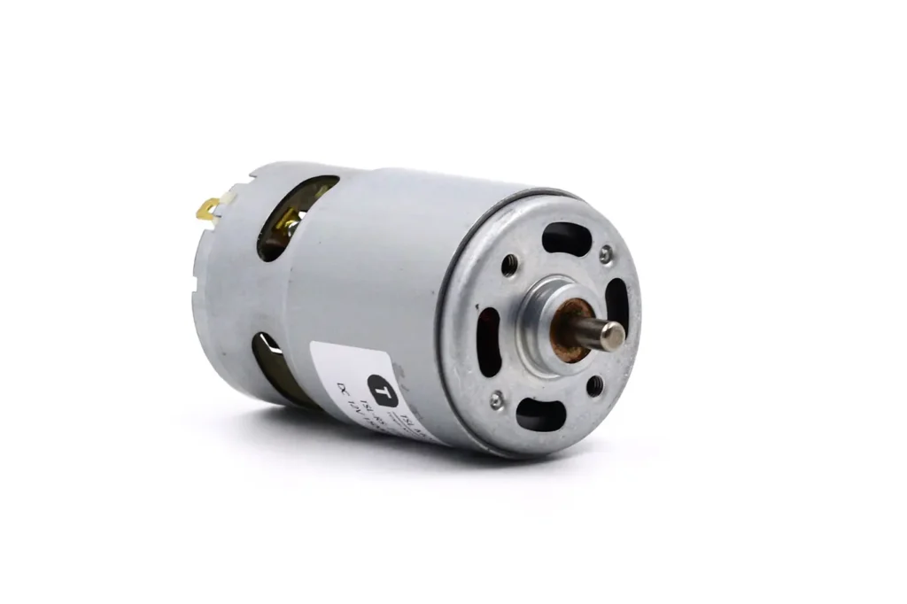
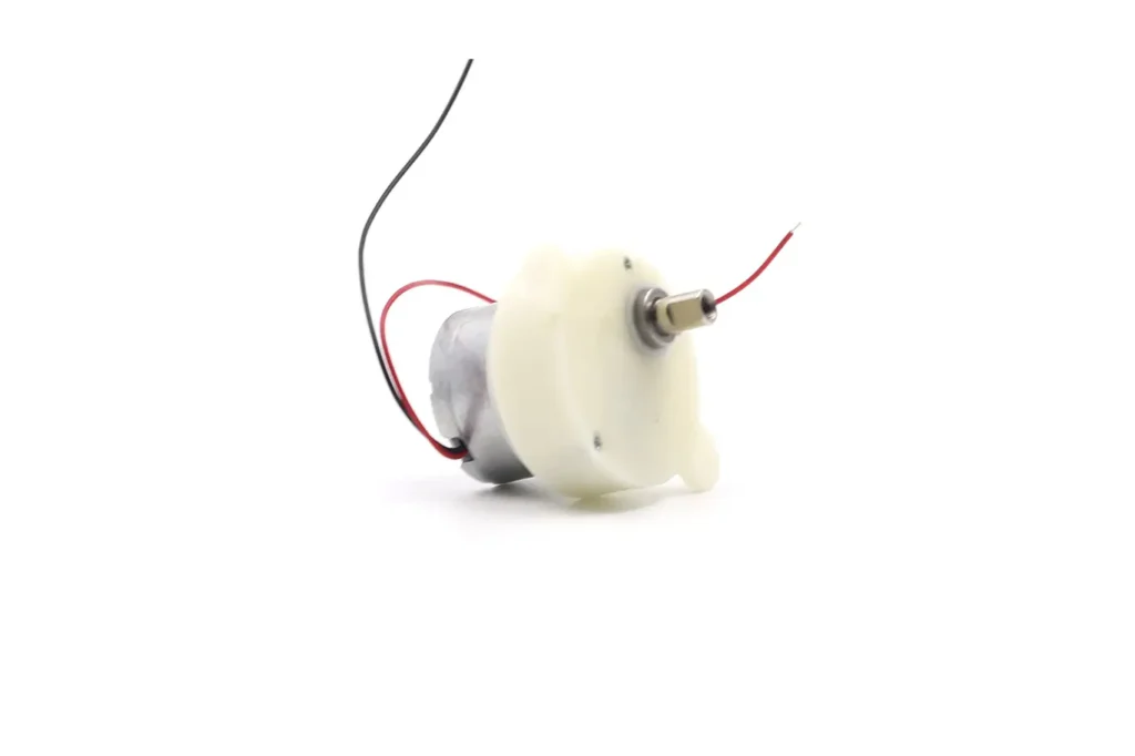
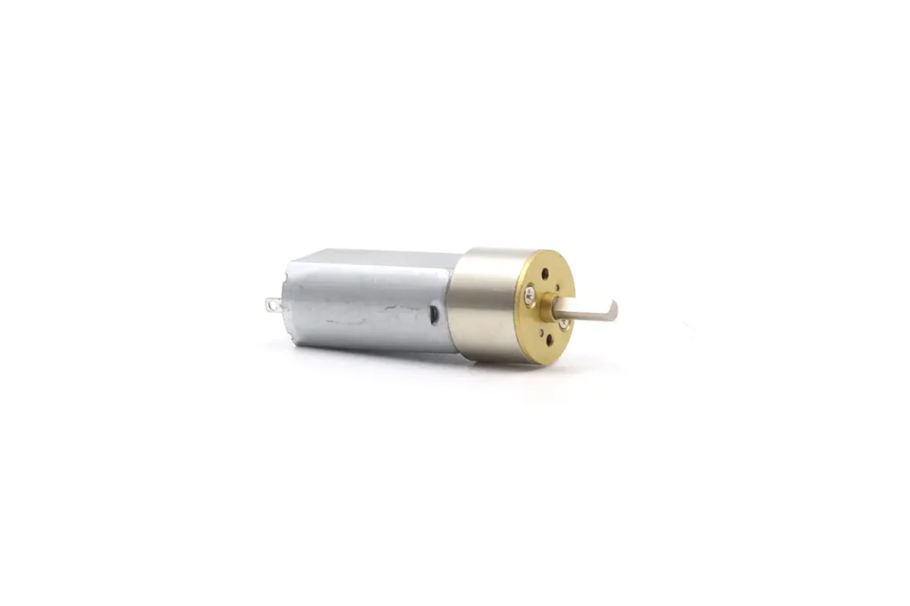
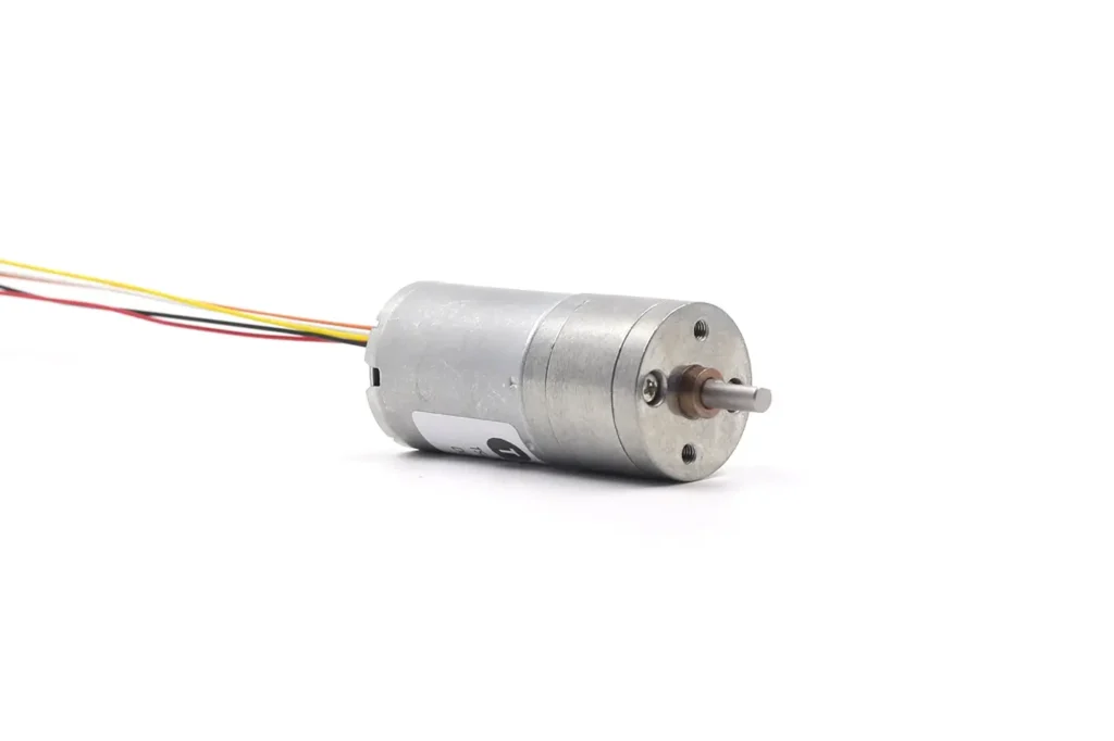
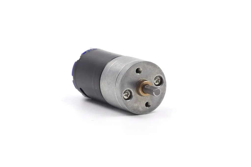
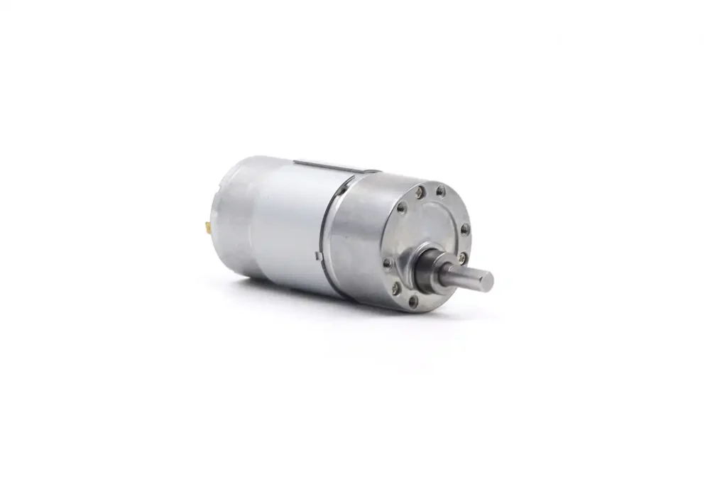
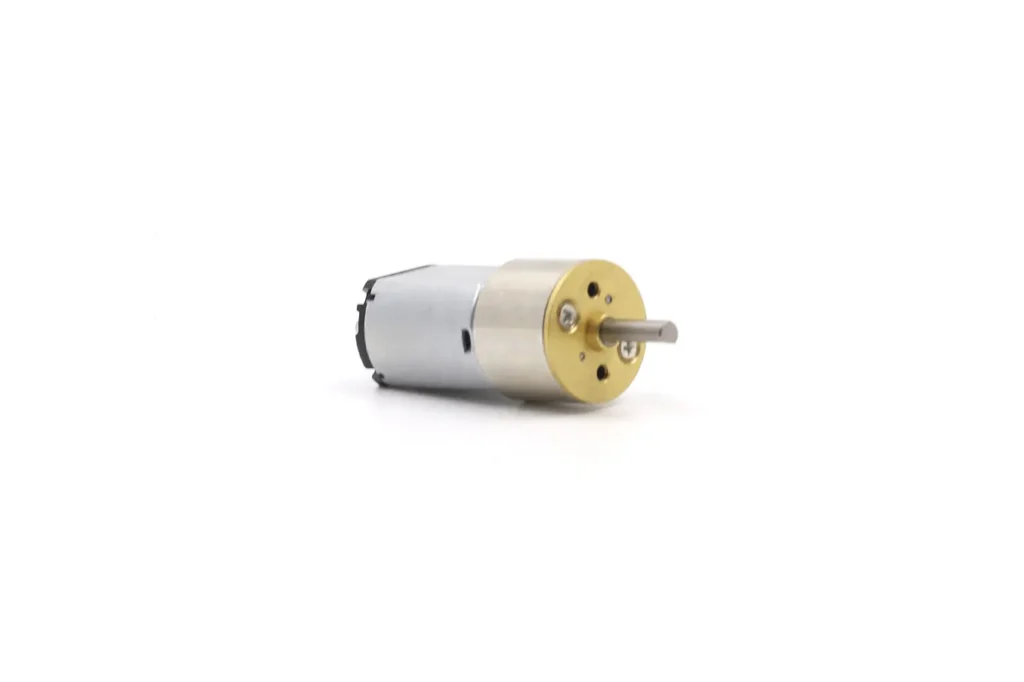
1.Cylindrical Geared Motors (Coaxial)
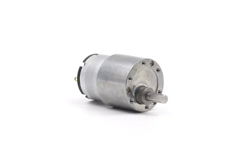
This is the classic configuration where the gearbox is a cylinder extending axially from the motor face.
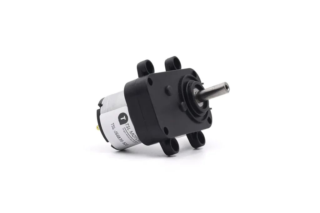
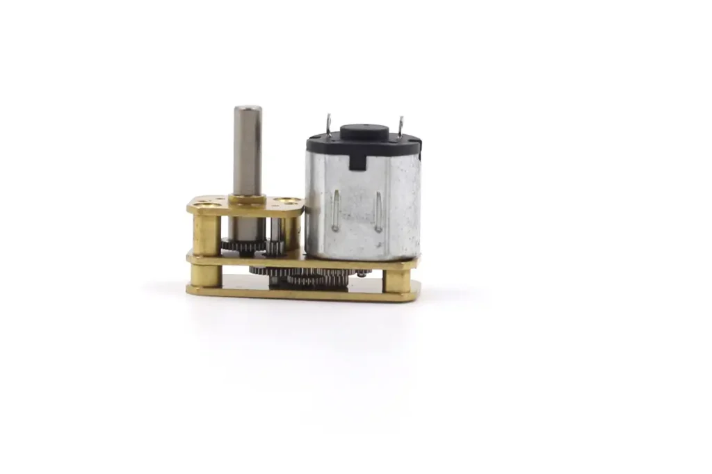
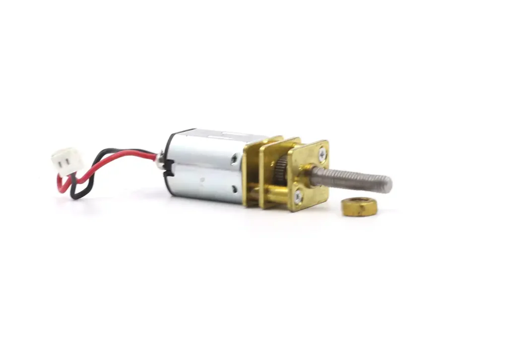
2.Flat/Square Geared Motors (Box Type)
Also known as an “offset” gearbox, this is characterized by a gearbox that is wider and flatter than the motor.
Design: Gears are arranged in a rectangular housing, often resulting in the output shaft being offset from the motor shaft’s axis.
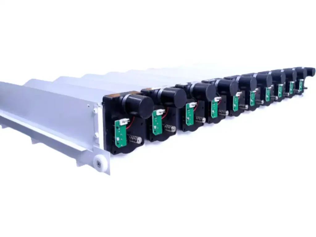
Vending Machine Dominance: This profile is ubiquitous in the vending machine industry. The flat shape allows motors to be tightly stacked side-by-side (e.g., a row of snack spirals), optimizing product density on the shelf.
Mounting: Square gearboxes typically have standardized mounting holes on the face or side, and the shafts are often “D-cut” or hexagonal for direct insertion into the mechanism without set screws, facilitating quick replacement by technicians.
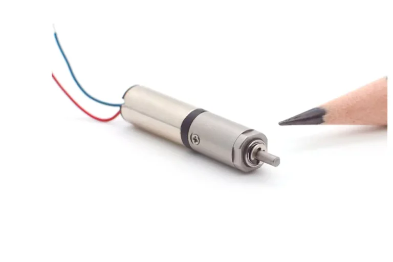
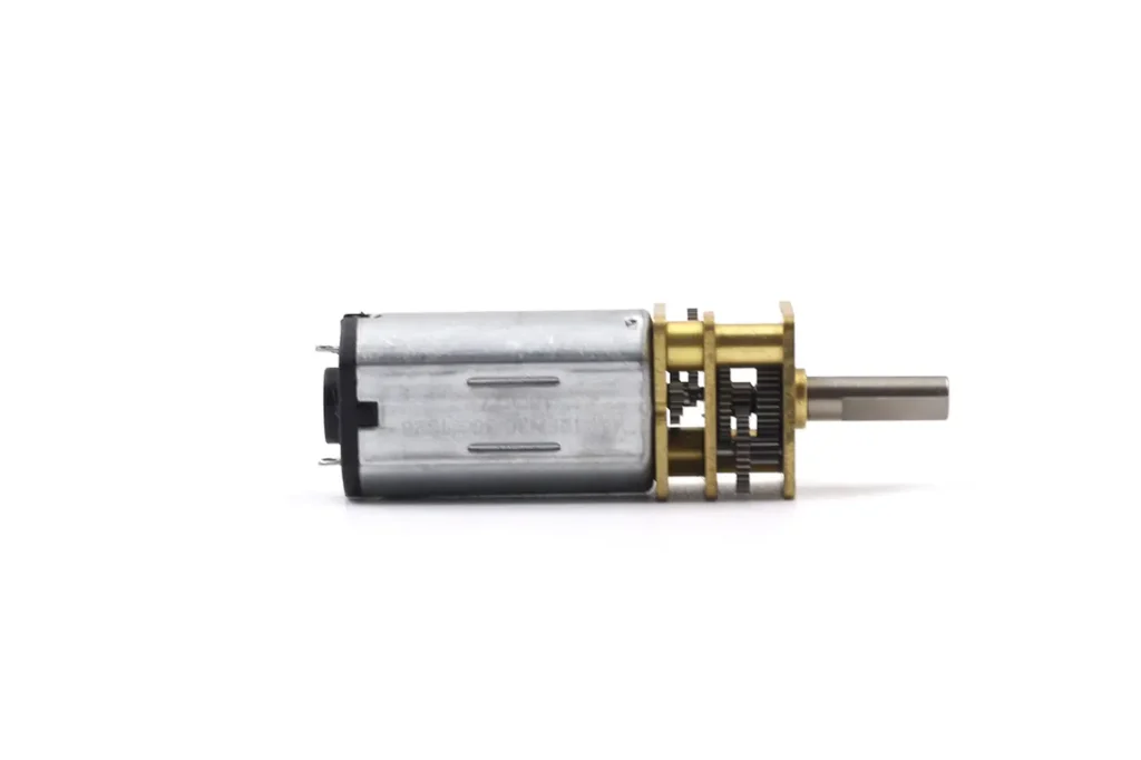
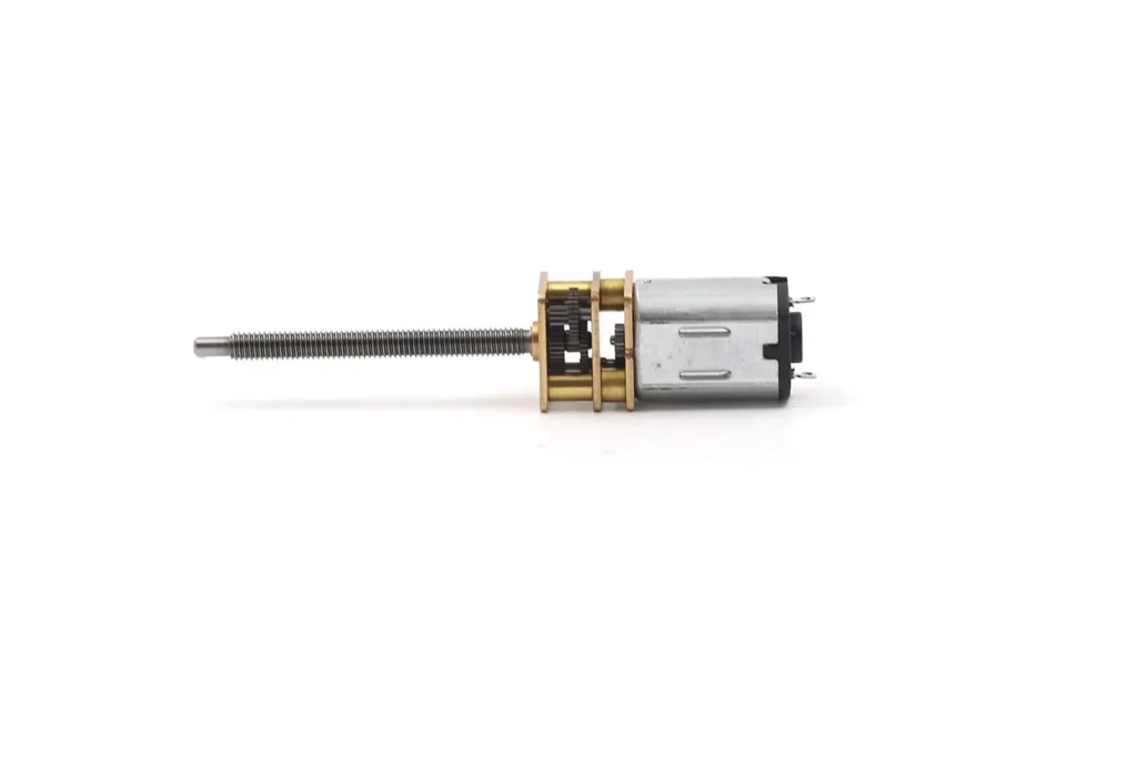
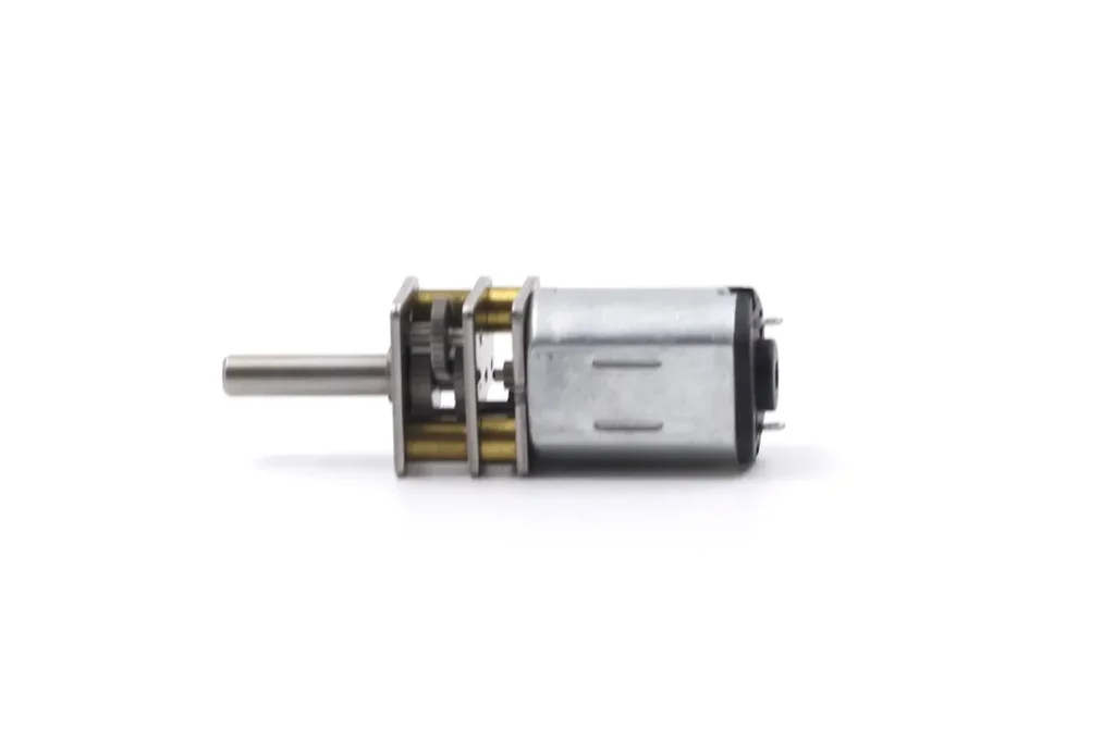
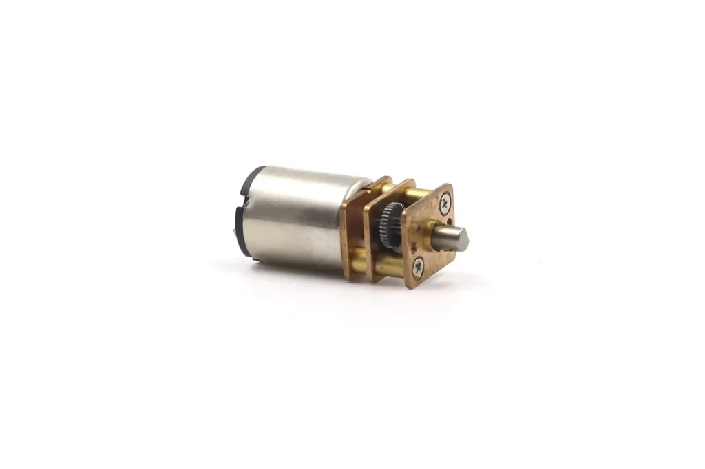
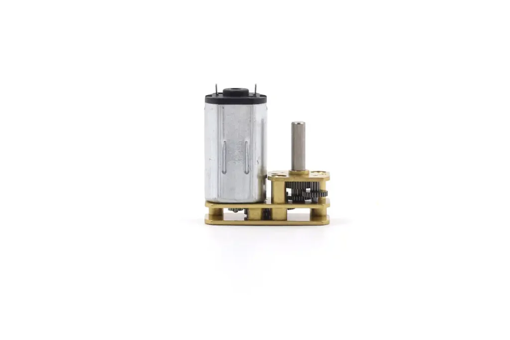
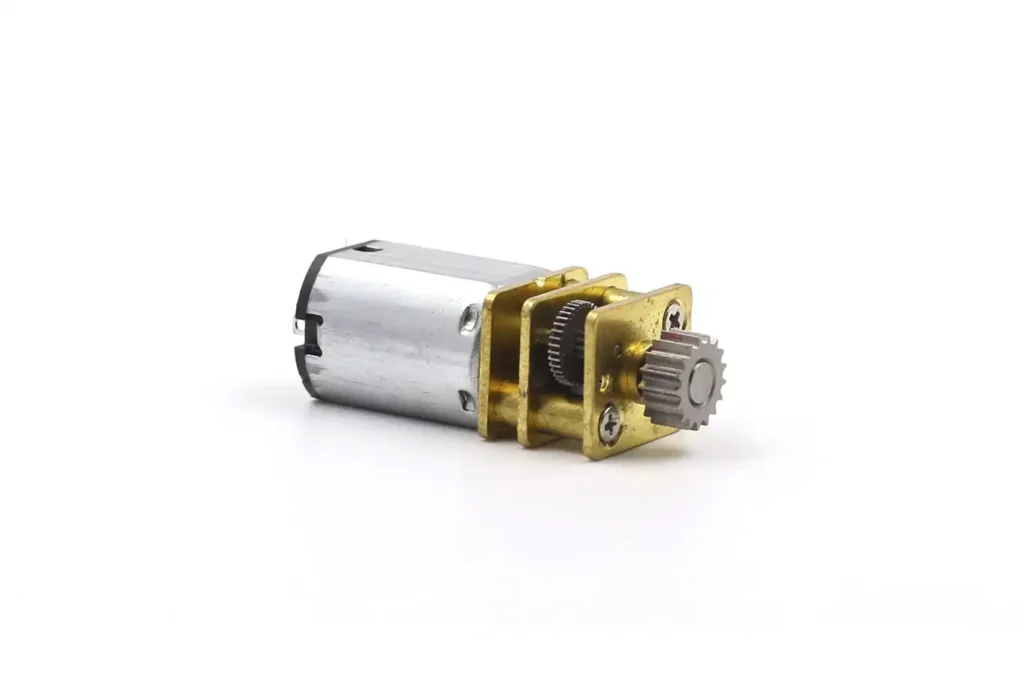
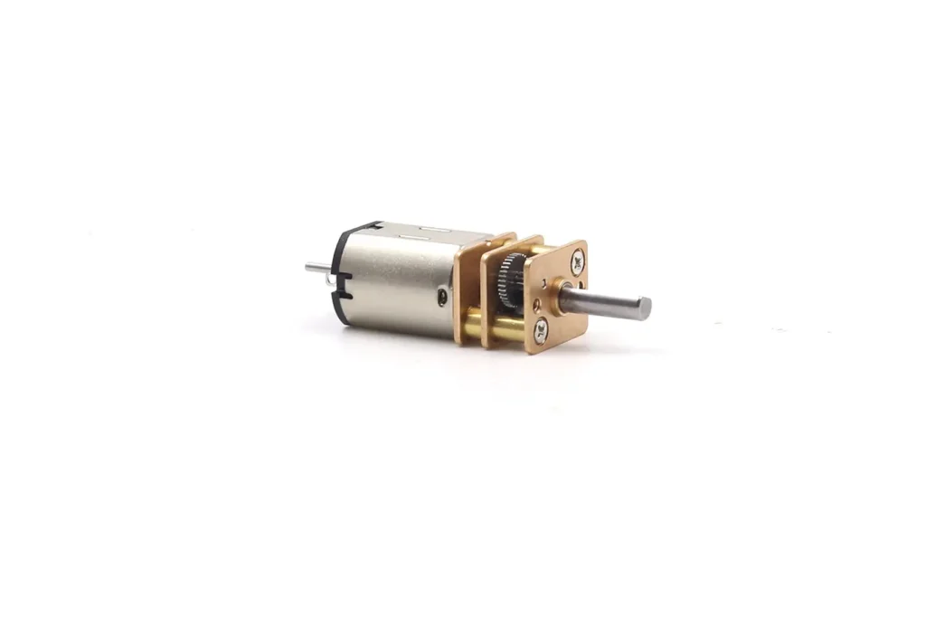
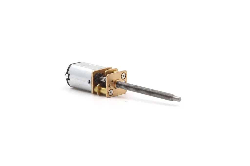
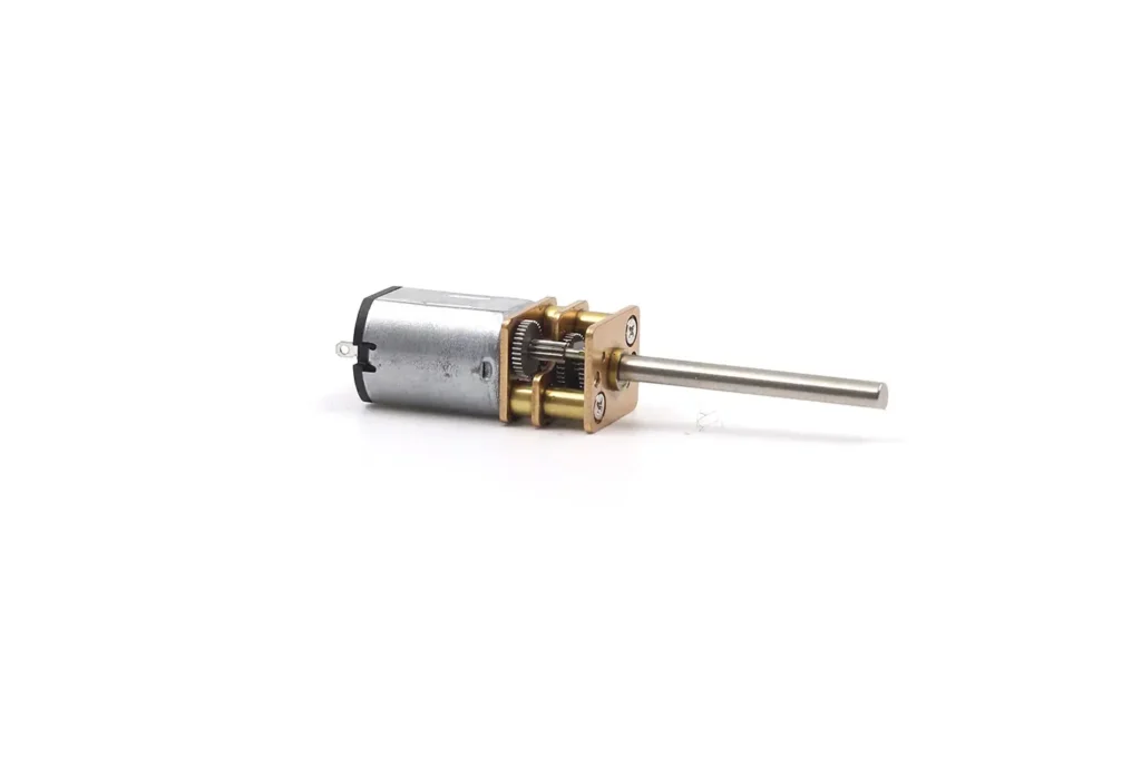
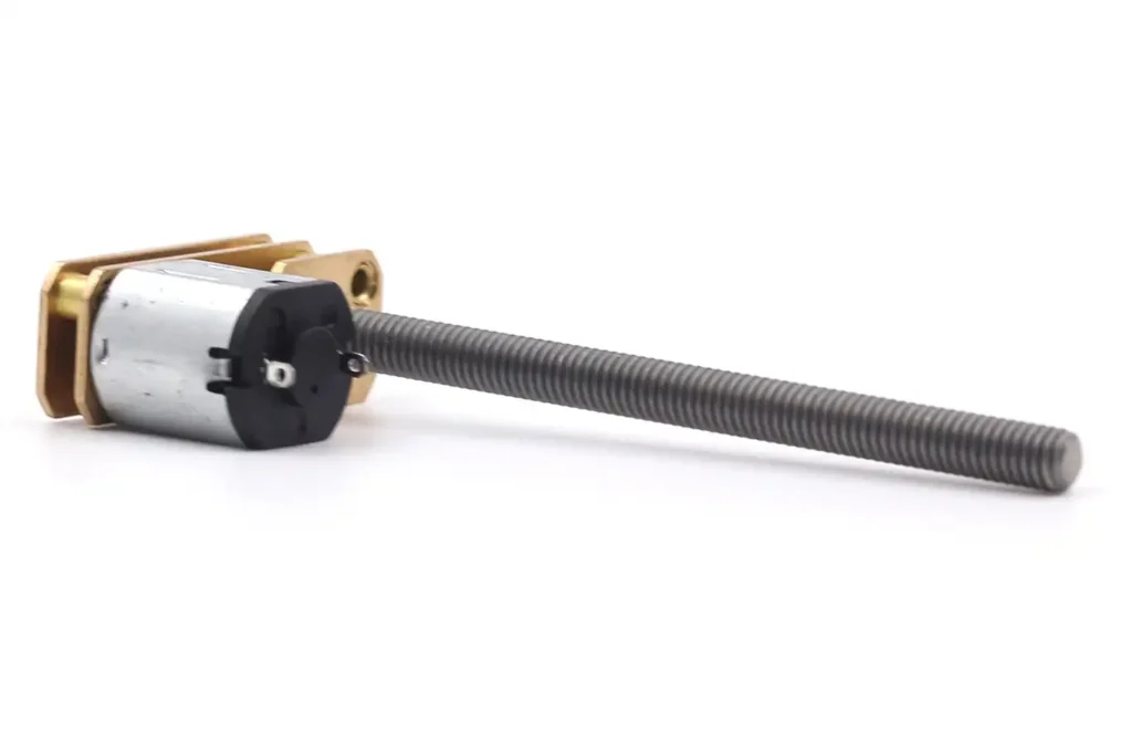
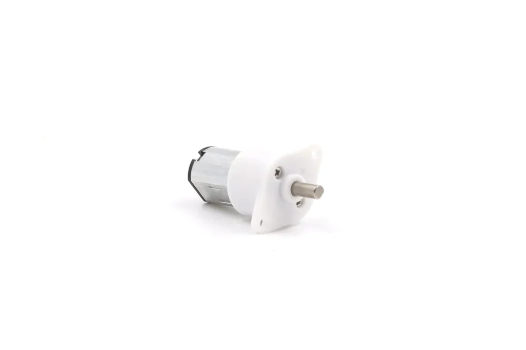
Design: They are extremely compact, typically featuring a 12mm x 10mm cross-section with an exposed metal gearbox casing.
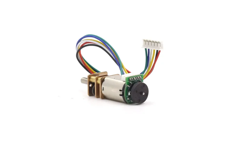
Significance: Due to their surprising torque-to-volume ratio and availability, N20s have become the de-facto standard for micro-robotics, electronic locks, and 3D printing pens. Modern iterations often include an extended rear shaft to accommodate a magnetic encoder, allowing for sophisticated closed-loop control.
3.N20 Miniature Geared Motors
Spur Gear Motor: Advantages and Disadvantages
To select a spur gear motor effectively, engineers must balance its capabilities against its limitations based on specific application requirements.
Advantages: Reasons for Selection
Cost-Effectiveness:
Spur gear motors are typically the most economical choice among geared motors.
Compared to the complex curves of helical gears or the multi-component assembly of planetary systems, the spur geometry is simpler and faster to manufacture—whether by hobbing, sintering, or molding.
For budget-constrained projects like toys, vending machines, or consumer appliances, they are often the only viable option.
High Efficiency:
With efficiency ratings of 95-98% per stage, spur gears waste very little energy. This efficiency stems from a pure rolling/sliding contact, without the parasitic losses of axial thrust or high sliding friction seen in worm drives.
Easy Integration:
The lack of axial thrust load simplifies mounting requirements. Designers do not need to over-engineer the housing to contain internal forces. Furthermore, the linear arrangement of the gears makes the system easier to inspect and troubleshoot compared to the enclosed complexity of a planetary gearhead.
Back-Drivability :
In many spur gear designs (depending on the ratio), the output shaft can be turned by an external load when the motor is off. This is a safety feature in applications like automatic doors or conveyors, which may need to be manually pushed during maintenance.
Disadvantages: Engineering Constraints
Acoustic Noise:
This is the most significant drawback. The line contact of spur teeth leads to an immediate, full-width engagement.
As speed increases, this sudden impact generates considerable noise and vibration, often described as a “whining” sound. In noise-sensitive environments like hospitals or offices, this can be disqualifying unless expensive plastic gears or damping grease are used.
Lower Load Capacity:
In a spur gear mesh, the load is typically transmitted through a single pair of teeth (or at most two) at any given moment. The contact ratio is usually between 1 and 2.
In contrast, a planetary gearbox simultaneously distributes the load across multiple planet gears (often 3 or 4). This makes spur gears more susceptible to tooth breakage under shock loads or extreme torque peaks.
Backlash:
Spur gear trains typically exhibit moderate backlash (the clearance between teeth). While acceptable for continuous motion applications like pumps or fans, this is detrimental to precision positioning (e.g., robotic arms) unless cost-adding anti-backlash mechanisms (like spring-loaded split gears) are employed.
Size-to-Torque Ratio:
To achieve very high torque, spur gears need to be physically large or stacked into a long, multi-stage gear train. Due to its load-sharing geometry, a planetary gearbox can achieve the same torque in a denser, more compact package.
Spur Gear vs Planetary Gear vs Helical Gear vs Worm Gear
Engineering selection is fundamentally about trade-offs. Here, we systematically compare the spur gear motor with its primary rivals to illuminate the best scenarios for application.
Spur Gear Motor vs. Planetary Gear Motor
| Characteristic | Spur Gear Motor | Planetary Gear Motor |
| Load Capacity | Low/Medium. Load is borne by a single pair of teeth. | High. Load is shared among 3+ planet gears. |
| Efficiency | High (95-98%/stage). Highly efficient. | High (90-95%/stage). Slightly lower due to churning. |
| Noise | High. Impact noise from straight teeth. | Low. Smoother engagement, generally much quieter. |
| Compactness | Medium. High ratios require length. | High. Highest torque density for the volume. |
| Cost | Low. Simple manufacturing/assembly. | High. Complex assembly and precision parts. |
| Alignment | Offset (usually) output shaft. | Coaxial (inline) output shaft. |
Conclusion: Choose Spur for cost-sensitive, medium-load applications that are not noise-sensitive (e.g., vending machines, simple actuators). Choose Planetary for high-torque, space-constrained, or precision applications (e.g., robotic joints, power screwdrivers, aerospace actuators).
Spur Gear Motor vs. Worm Gear Motor
| Characteristic | Spur Gear Motor | Worm Gear Motor |
| Output Shaft | Parallel to the motor shaft. | At a right angle (90°) to the motor shaft. |
| Self-Locking | No. Back-drivable. | Yes (usually). Load cannot turn the motor. |
| Efficiency | High (95%+). | Low (50-90%). Significant sliding friction. |
| Reduction Ratio | Low per stage (1:2 to 1:10). | High per stage (up to 1:100). Compact high reduction. |
Conclusion: Choose Spur for efficiency and when a parallel shaft is required. Choose Worm when you need a right-angle drive, a self-locking feature (e.g., a hoist or crane that should not drop when power is off), or a very high reduction in a single stage.
Spur Gear Motor vs. Helical Gear Motor
Helical gears are essentially spur gears that are angled. They represent an evolution of the spur concept.
- Noise: Helical gears are quieter and smoother because the angled teeth engage gradually instead of abruptly.
- Cost: Helical gears are more expensive to manufacture due to the complex geometry.
- Thrust: Helical gears generate axial thrust forces, which require stronger, more expensive bearings (thrust bearings or tapered roller bearings).
Conclusion: Spur gears remain the choice in miniature motors where bearing simplicity outweighs acoustic improvement and in cost-sensitive industrial motors. In large, high-power industrial gearboxes, helical gears generally supersede spur gears to reduce noise and vibration.
Application Engineering: Automation Case Studies
The theoretical advantages of the spur gear motor translate into specific roles across various industries. We examine four distinct scenarios where the spur gear motor is the dominant solution.
Vending Machine Mechanisms: The Niche of the Square Geared Motor
The vending machine industry is perhaps the largest single consumer of “square” or “box-type” spur gear motors.
Mechanism: In a standard spiral vending machine, products are stored on a spiral coil. To dispense a product, the coil must rotate 360 degrees.
Engineering Challenge: The motion requires high torque to push potentially stuck products (like a heavy bag of candy caught against the glass) but runs at a very low speed (10-25 RPM). Additionally, a single machine may have 40–60 such coils, so the motors must be cheap and compact to maximize shelf density.
Spur Gear Motor Solution:
Cost: The low unit cost of the spur gear is paramount when multiplied by 60 motors per machine.
Geometry: The flat/square shape allows motors to be mounted side-by-side with minimal clearance. The offset shaft aligns perfectly with the coil center while hiding the motor body behind the product channel.
Installation: The industry’s square gearboxes often feature D-cut or Double-D shafts that insert directly into the coil mechanism without screws. This allows technicians to replace a faulty motor in seconds without tools—a critical maintenance feature.
Voltage: These motors typically run on 24V DC, the standard safe voltage for vending machine control.
Micro-Robotics: The N20 Standard
In the education and hobbyist robotics space (e.g., line-following robots, micro-sumo robots), the N20 spur gear motor is the industry standard.
Engineering Challenge: Robots need to be small, battery-efficient, and controllable.
Spur Solution:
Size: The 12mm cross-section fits into tiny chassis designs.
Control: The modern trend is for these motors to be equipped with a magnetic Hall Effect encoder on the extended rear shaft. This provides feedback (pulses per revolution), allowing the robot’s microcontroller to use a PID (Proportional-Integral-Derivative) algorithm to maintain a precise speed regardless of battery voltage drop or terrain changes.
Durability: Despite the tiny size, the all-metal spur gear train is surprisingly robust against the stall currents typical in robot combat or obstacle navigation.
Industrial Conveyors: Efficiency vs. Reliability
For small to medium-sized assembly line conveyors, the spur gear motor is often preferred over the worm gear.
Engineering Challenge: Continuous operation for 8-16 hours per day (S1 duty cycle). Energy costs and heat dissipation are concerns.
Spur Solution:
Efficiency: In continuous duty applications, the high efficiency of the spur gear means less energy consumption and, crucially, less heat generation compared to a worm gear. A continuously running worm gear can get hot enough to degrade its lubricant; a spur gear runs cooler.
Back-Drivability: In a manual assembly line, operators may need to manually push the belt to adjust product spacing when the power is off. A spur gear motor allows this, while a high-ratio worm gear would lock the belt, frustrating the operator.
Medical Devices: The Shift to Silent Plastic
Application: Peristaltic pumps for intravenous (IV) infusion, dialysis machines, and lab automation.
Engineering Challenge: Quiet environment (hospital rooms) and sterile. Lubricant leakage is unacceptable.
Spur Solution:
Material: Medical devices often use engineered plastics like PEEK or POM. These materials are biocompatible and can run quietly without liquid lubricants, avoiding contamination of sterile environments.
Noise: While spur gears are inherently noisier, using plastic gears combined with a high-viscosity damping grease (such as Molykote) can reduce the noise to a whisper-quiet level, suitable for bedside equipment.
How to Choose and Size the Right Motor
Selecting a motor is a mathematical process, not a guessing game. An undersized motor will overheat and fail; an oversized motor wastes money and space. The guide below outlines a rigorous selection workflow.
Before browsing any catalog, define these variables:
- Rated Voltage: (e.g., 6V, 12V, 24V, 48V DC). Higher voltages generally allow for lower current and better efficiency at the same power.
- Output Speed (RPM): The target speed after gearbox reduction.
- Rated Torque: The continuous torque the motor must deliver without overheating.
- Stall Torque: The peak torque at zero speed. Rule of Thumb: Select a motor where the working torque is only 20-30% of the stall torque. This safety margin ensures the motor runs cool and has “headroom” for starting heavy loads.
- Duty Cycle: Is the operation continuous (S1) or intermittent (S2/S3)? Spur gears handle continuous operation well due to low heat generation.
- Shaft Type:
- D-cut: Common for set-screw locking (easy to secure).
- Round: Requires a press-fit or collet.
- Threaded: Used for linear actuators (lead screws).
- Knurled: Used for pressing into plastic wheels.
- Environmental Rating (IP): Does it need dust protection (IP5x) or water resistance (IPx4/x7)? Most open-frame spur gearboxes are IP20 (no protection).
Still not sure how to choose the right motor? Contact us, and we will customize the most suitable motor for your project.
Maintenance, Noise Reduction, and Troubleshooting
Even the most reliable spur gear motor requires care. Understanding failure modes and acoustic management is key to long-term success.
Lubrication and Noise Control
Lubrication serves three purposes: reducing friction, dissipating heat, and damping noise.
Metal Gears: Require periodic grease replenishment. Lithium-based grease is standard for steel gears.
Plastic Gears: While often advertised as “self-lubricating,” plastic gears benefit greatly from compatible grease.
Critical Warning: Never use standard petroleum-based mineral greases on plastic gears. They cause chemical degradation (swelling/cracking) of materials like polycarbonate or ABS. Engineers must specify a silicone- or PTFE-based synthetic grease formulated for plastic-on-plastic or plastic-on-metal compatibility (e.g., Molykote EM-30L or Shin-Etsu G-501).
Damping Greases: For applications requiring a “premium” haptic feel or significant noise reduction (e.g., volume knobs, automotive HVAC actuators), use a high-viscosity damping grease. These thick, heavy greases cling to the gear teeth and physically suppress vibration, eliminating the “chatter” typically associated with spur gears.
Common Failure Modes and Troubleshooting
Symptom1:Excessive grinding noise
Possible Cause:Gear teeth wear (pitting) or lack of lubrication.
Engineering Solution:Check for pitting on the gear teeth. Clean the gearbox and refill with high-viscosity damping grease.
Symptom2:Rhythmic clicking sound
Possible Cause:Broken gear tooth.
Engineering Solution:Replace the gearbox immediately. Loose tooth fragments will eventually jam the mesh and destroy the motor.
Symptom3:Motor spins, shaft is stationary
Possible Cause:Stripped gear (often the first plastic stage) or pinion has come loose.
Engineering Solution:Common in plastic gearboxes stalled under load. The first stage spins too fast and melts or shears. Replace the unit.
Symptom4:Overheating
Possible Cause:Overloaded or exceeding the S2 duty cycle.
Engineering Solution:Check the load current against the rated current. If current is high, the motor is undersized. Improve ventilation.
Symptom5:Intermittent operation
Possible Cause:Brush wear (DC motor) or loose wiring.
Engineering Solution:Check carbon brushes. In inexpensive micro-motors, the brushes are often non-replaceable; the motor has reached its end of life.
👉 If you cannot identify the fault or are unsure which motor replacement to choose, please contact us — we will provide you with the most satisfactory solution.
Conclusion
The spur gear motor remains a cornerstone of mechanical engineering not because it is the newest technology, but because it represents the optimal balance of efficiency, simplicity, and cost.
While it may lack the torque density of a planetary gearbox or the self-locking utility of a worm drive, its high transmission efficiency and ease of manufacture make it the best choice for a huge variety of applications—from the vending machine dispensing your morning coffee to the conveyor belt assembling your smartphone.
For engineers in 2024 and beyond, the key is nuanced selection: knowing when to leverage the quiet operation of PEEK plastic gears, when to capitalize on the torque of a square gearbox for shelf density, and how to size the motor with an adequate safety margin to prevent failure.
With advancements in materials and the integration of smart sensors, the humble spur gear motor will continue to drive automation forward, proving that sometimes, the most effective solution is the one that is simple, direct, and just works.
Are you specifying a motor for your next automation project? Don’t leave critical variables like torque, duty cycle, and environmental resistance to chance.
Review the detailed specifications for high-efficiency N20, square, and cylindrical spur gear motors, and apply the sizing calculations provided in this report to ensure your design meets the rigors of the real world.
FAQ
Q1: What is a Spur Gear Motor?
A: It is an assembly integrating a high-speed motor with a spur gear reduction gearbox to lower speed and increase torque.
Q2: What is its core principle of operation?
A: The core principle is “Speed Down, Torque Up,” achieved through cascaded small gears driving larger gears.
Q3: What are the biggest advantages of a spur gear motor?
A: Cost-effectiveness and high transmission efficiency (over 95% per stage).
Q4: Why is it noisy?
A: Because the straight gear teeth engage with an instantaneous, full-width impact, causing vibration and noise.
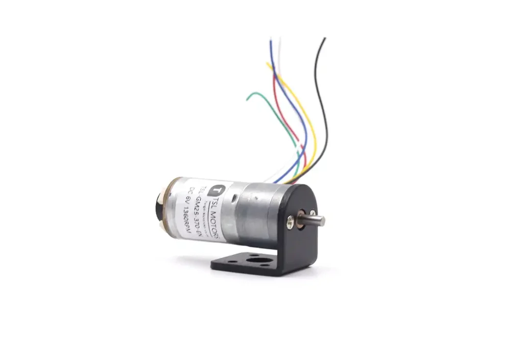
TSL-Motor: Custom Motor Solutions
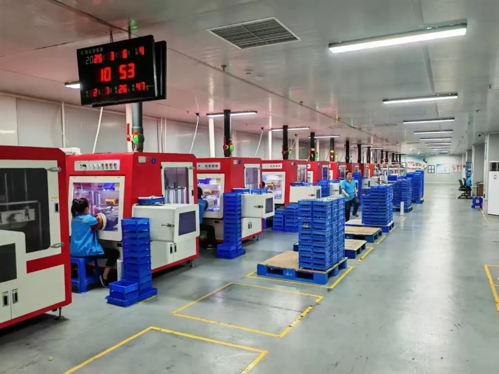
Established in 2009, TSL Motor has evolved into a leading innovator in precision drive systems and specialized motor manufacturing. Our 15,000㎡ advanced production facility in Shenzhen houses a skilled workforce of 200+ professionals, delivering an annual output of 2 million units to global markets.
Continuous R&D investment in energy-efficient motor technologies
Lean manufacturing processes ensuring cost-competitive pricing
Agile production capacity scaling for batch customization
Global compliance certifications (CE, RoHS, REACH)
With dual focus on operational excellence and client success, Twin Motor empowers businesses worldwide to achieve technological differentiation. Our engineering team welcomes complex challenges across automotive, robotics, and smart infrastructure applications.
Contact our solutions center to discuss your project requirements or request our technical portfolio.
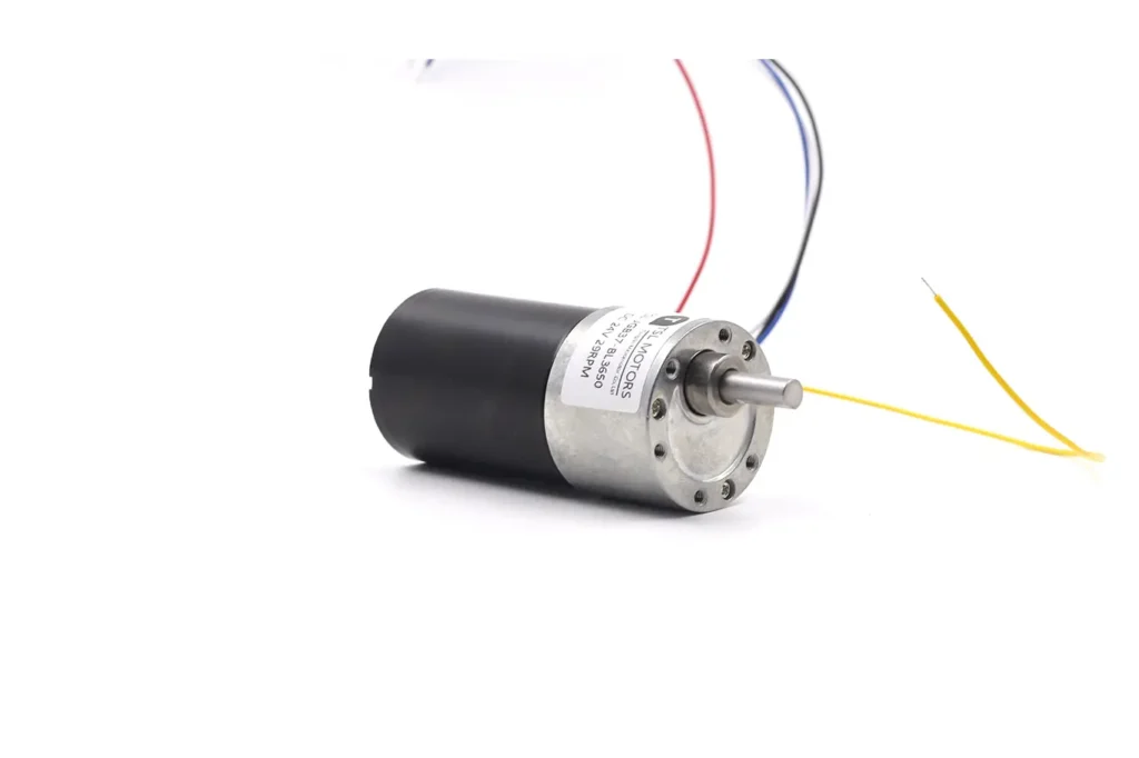
Spur Gear Motor
TSL Motors provides compact and reliable spur gear motors designed for cost-efficient performance. Our motors meet a wide range of application needs with various reduction ratios, voltages, sizes, and precision gear options, including steel or brass gears.