From the grinder waking you up in the morning, to a car’s electric windows, and the electric toys in children’s hands, you may not realize that an old and reliable technology is quietly working all around us. This is the Brushed Direct Current (DC) Motor.
It is the pursuit of motor reliability, efficiency, and widespread application that has shaped the development of the entire industry.
And we, Tsinglin Motor, are part of this technological revolution. We specialize in DC motor manufacturing, with over a decade of rich experience, and have been a leader in China’s DC motor manufacturing field.
In this ultimate guide, we will provide an in-depth yet accessible look at the secrets of the Brushed DC Motor, sharing our insights as industry experts.
Key Takeaways
- Brushed DC Motor Commutation: The brushed dc motor(BDC) relies on brushes and a commutator to constantly reverse the current direction, forcing the rotor to “chase” the fixed field, resulting in uninterrupted rotation.
- BDC Core Components: The motor’s operation is defined by the interaction between the Stator, Rotor, Commutator, and Brushes.
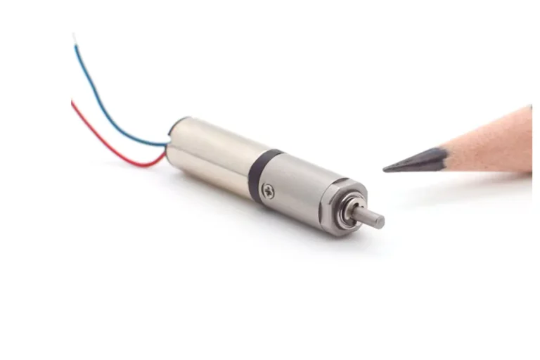
- Coreless BDC Advantage: Coreless (Hollow-Cup) motors are chosen for their extremely low inertia, fast response time, and zero cogging torque smoothness, ideal for high-precision, low-torque applications.
- BDC Control Simplicity: Speed is easily and efficiently managed by controlling the voltage, typically using PWM. Direction is controlled by simply reversing the voltage polarity.
- BDC Market Positioning: Despite lower efficiency than BLDC, BDC motors remain the preferred economic solution for mass-market applications due to their unbeatable low cost and sufficient reliability.
- BDC Industry Value: The BDC motor’s continued relevance proves that in engineering, cost-effectiveness and reliability are often the deciding factors over pure technical performance.
What is A Brushed DC Motor?
A DC motor is a device that converts DC electrical energy into mechanical energy. Its core operating principle is based on “electromagnetism” and the “interaction of magnetic poles.” When current flows into the motor’s stator (stationary part) and rotor (rotating part), they each generate a magnetic field. These two magnetic fields attract or repel each other, generating a torque that drives the rotor to rotate continuously, outputting power to drive other equipment.
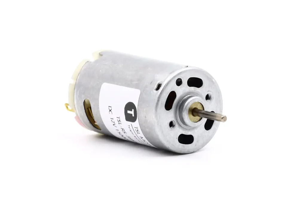
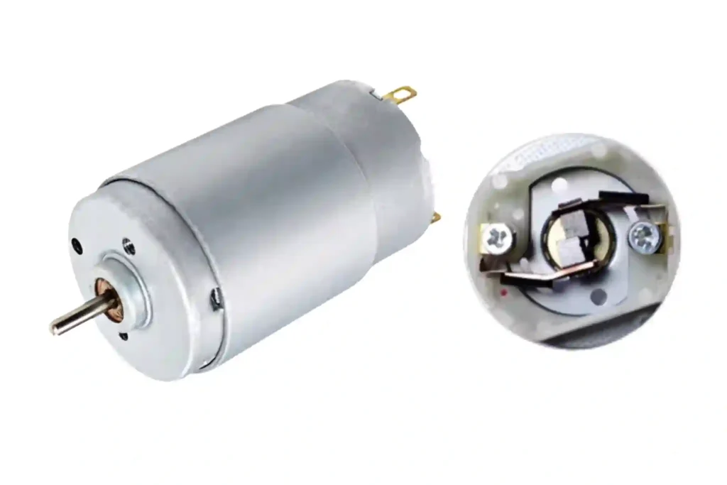
The Brushed DC motor is the most classic and common type of DC motor. Its name comes from its key physical structure—the “brushes.” This type of motor typically uses permanent magnets as the stator to create a fixed magnetic field, while the rotor is made up of winding coils. To achieve continuous rotation of the rotor, the direction of the current flowing through the rotor coils must be continuously changed, a crucial task performed jointly by the brushes and the commutator.
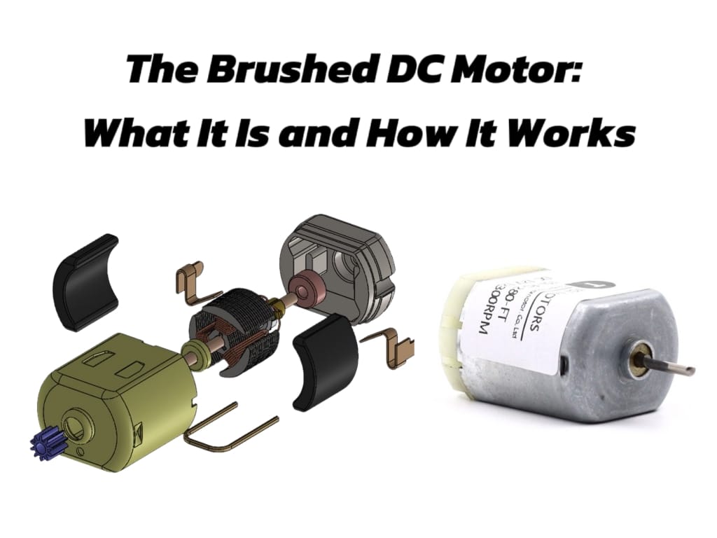
Brushed DC Motor Structure
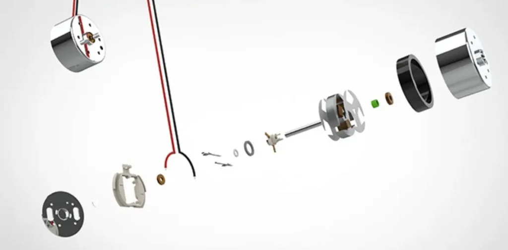
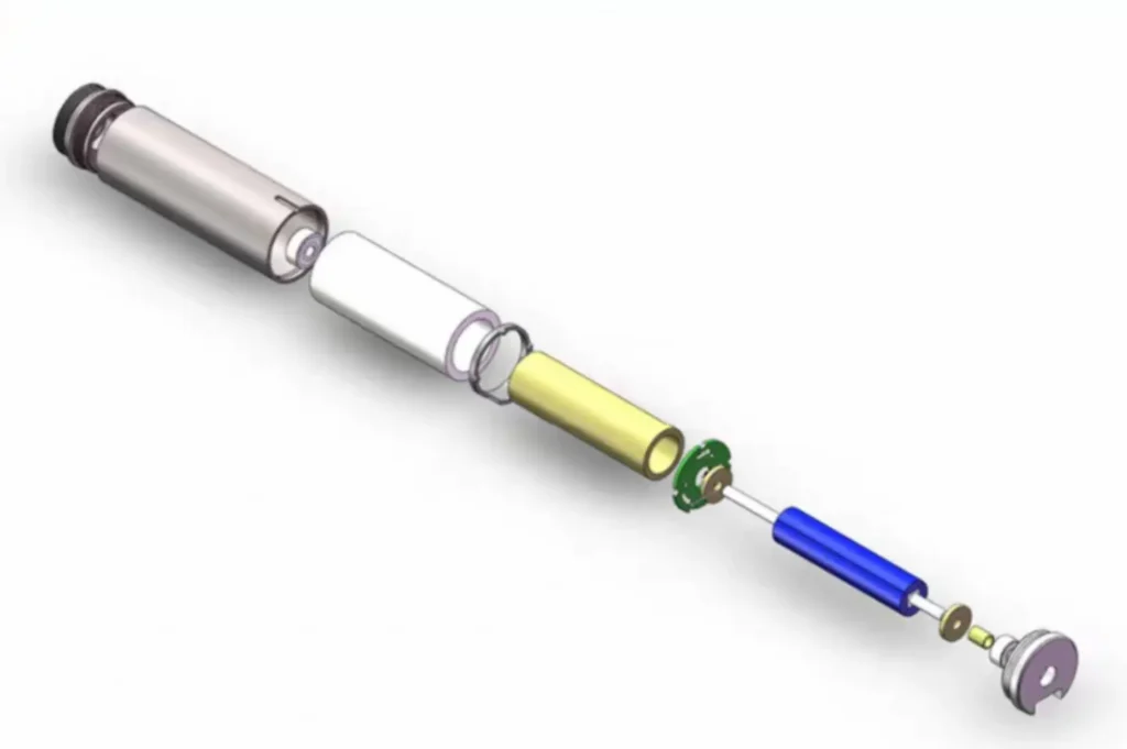
All Brushed DC motors consist of four basic components: the Stator, the Rotor (Armature), the Commutator, and the Brushes. We can understand their construction intuitively through an exploded view.

Stator
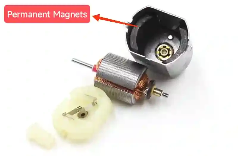
The stator is the motor’s stationary outer part, and its core function is to produce a fixed magnetic field. This magnetic field can be generated in two ways:
1.Permanent Magnets: Using arc-shaped permanent magnets with opposite polarities. This design is common in Permanent Magnet DC (PMDC) motors, which are usually smaller, lighter, and more efficient because the stator itself does not consume electrical energy. For permanent magnet stators, the stable magnetic field is generated by the inherent magnetism of the permanent magnets.
2.Electromagnetic Windings (Field Coils): Using coils that become electromagnets when current passes through them. This design is known as a wound-field motor, which, although structurally more complex, allows for more control over the motor’s performance characteristics.
Rotor
The rotor, also called the armature, is the internal rotating part of the motor. It contains electromagnets that interact with the stator’s magnetic field, generating the torque that drives the motor’s rotation. Its main components include:
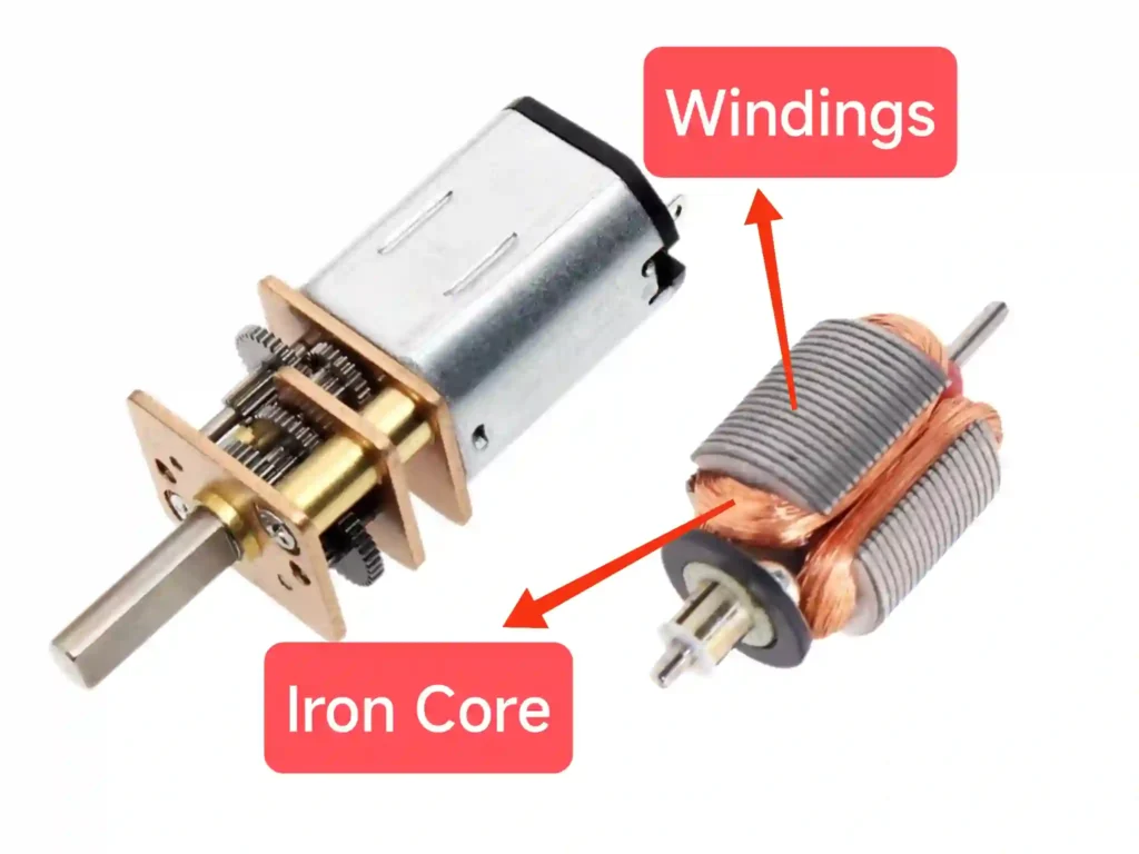
Windings/Coils: Copper wires wound around an iron core. The number of coils and their winding configuration determine the motor’s performance.
Iron Core: The coils are typically wound on a laminated iron core, which not only provides sturdy support for the coils but also helps concentrate the magnetic field and dissipate heat.
Commutator
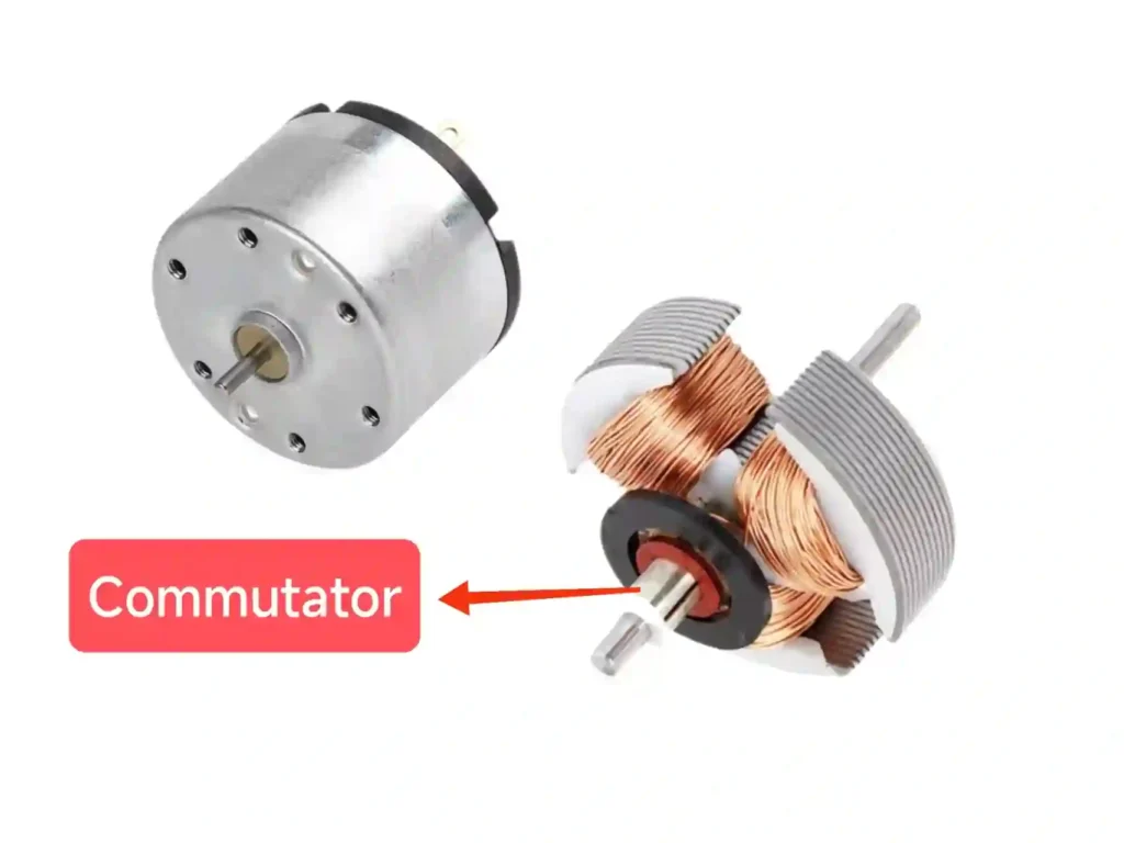
The commutator is the most ingenious part of the entire design—a rotating mechanical switch mounted on the rotor shaft. Its sole function is to periodically reverse the direction of the current flowing into the rotor windings.
It is made up of multiple mutually insulated copper segments, with each segment connected to one end of a rotor coil. Most motors have at least three commutator segments to avoid “dead spots” where the motor cannot start.
Brushes
The brushes are stationary conductive contacts that bridge the external DC power source and the rotating commutator. They are usually made of soft, conductive material (like carbon or graphite) and are spring-loaded to ensure continuous sliding contact with the commutator. In some low-current applications, precious metal brushes are also used.
How Does a Brushed DC Motor Work?
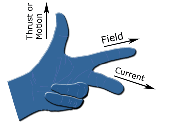
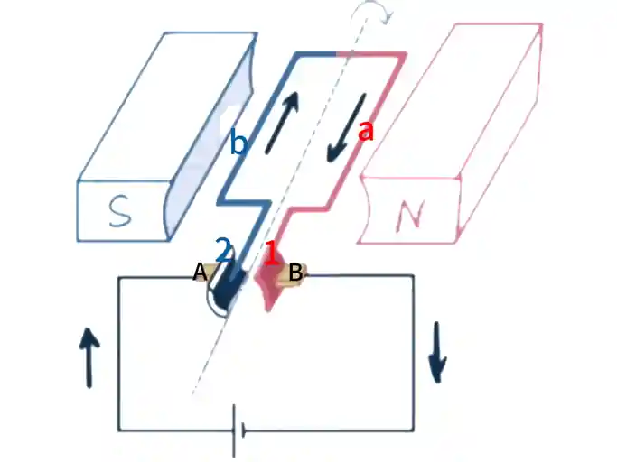
The core principle of a brushed DC motor is electromagnetic induction: when a current-carrying conductor (the rotor winding) is placed in a magnetic field (generated by the stator), it experiences a force, known as the Lorentz force. We can use Fleming’s Left-Hand Rule to intuitively determine the direction of this force, which reveals the relationship between magnetic field, current, and the direction of motion.
Detailed Working Process (Three-Step Breakdown)
Step 1: Initial State (Energization)
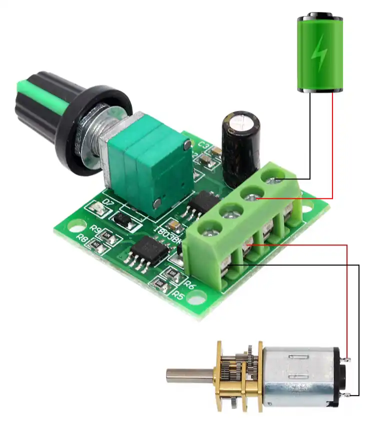
Assume we connect the DC motor to a direct current power source, such as a battery.
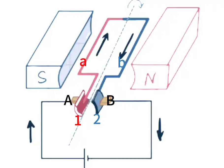
- Current flows out from the positive terminal, passes through one brush, and goes into a commutator segment.
- The commutator segment feeds the current into the rotor coil.
- After flowing through the coil, the current exits from the other commutator segment, passes through the second brush, and returns to the negative terminal of the power supply.
At this point, according to Fleming’s Left-Hand Rule (the Motor Rule): Extend your left hand so the magnetic flux lines (from N pole to S pole) pass through the palm. Let the four fingers point in the direction of the current. The thumb then indicates the direction of the force acting on the conductor.
- One side of the coil (e.g., the side near the N pole) has the current flowing inwards and receives a force directed to the right.
- The other side of the coil (the side near the S pole) has the current flowing outwards and receives a force directed to the left.
- These two forces are equal in magnitude and opposite in direction, forming a couple (or torque) that drives the rotor to begin rotating counter-clockwise.
Step 2: The Commutation Process (The Critical Step)
When the rotor rotates to the position where the plane of the coil is perpendicular to the magnetic field (known as the “neutral plane”), the torque previously generated becomes zero. If the current direction did not change, the rotor would coast past this point due to inertia, but the electromagnetic force it receives immediately after would become a reverse braking force, preventing continuous rotation.
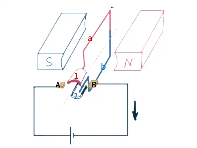
This is where the ingenious design of the commutator and brushes comes into play:
- As the rotor moves past the neutral plane, the commutator segments that were in contact with the brushes disconnect and switch to make contact with the opposite segments.
- This switching action instantaneously reverses the direction of the current flowing into the coil!
- The side that previously had current flowing inwards now has current flowing outwards; the side that previously had current flowing outwards now has current flowing inwards.
Step 3: Sustained Rotation
After the current direction has changed, we apply Fleming’s Left-Hand Rule again:
- Even though the physical positions of the two sides of the coil have swapped relative to the poles, because the current direction has also simultaneously reversed, the direction of the electromagnetic force received by the two sides of the coil remains the same (e.g., the force is still to the right on the left side, and still to the left on the right side).
- This sustained, unvarying torque pushes the rotor to continue rotating in the same direction (counter-clockwise).
Summary of the Cycle
Rotation -> Reach Commutation Point -> Brushes and Commutator automatically switch current direction -> Acquire a continuous unidirectional torque -> Continue Rotation. This process repeats constantly, allowing the motor to run continuously.
Types of Brushed DC Motors
Brushed DC motors can be classified based on the stator excitation method and the rotor structure.
Classification by Stator Excitation Method
Permanent Magnet (PMDC) Motors
The stator magnetic field is generated by permanent magnets. This is the most common type for small applications, known for its compact structure, reliability, and energy efficiency, as the stator field does not consume electrical power.
Wound-Field Motors
The stator magnetic field is generated by electromagnets (field coils). Based on how the field windings are connected to the armature windings, they are divided into three main subtypes:
- Series-Wound: The field coil is connected in series with the armature. This motor provides very high starting torque, but its speed varies greatly with the load. It is ideal for heavy-duty applications like cranes and winches.
- Shunt-Wound: The field coil is connected in parallel (shunt) with the armature. This motor has good speed regulation, running at a relatively constant speed regardless of load changes.
- Compound-Wound: Combines the characteristics of both series and shunt windings. It offers both high starting torque and good speed stability, suitable for applications requiring both.
Classification by Rotor Structure
Based on the classification by rotor structure, brushed DC motors are categorized into two types: iron-core motors and coreless motors.
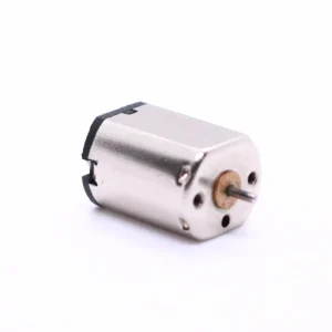
Iron-core Motors
This is the standard design, where the coils are wound on a laminated iron core. The structure is robust and produces high torque, but the mass of the iron core results in high rotational inertia and can cause “cogging effect” (a slight jerkiness) at low speeds.
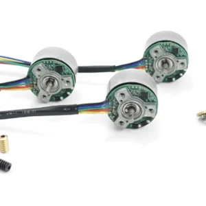
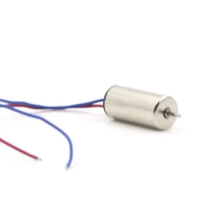
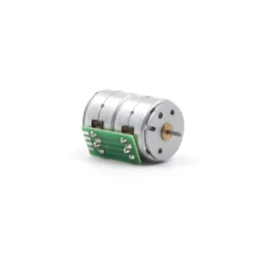
Coreless Motors
The rotor winding is a self-supporting, hollow structure, and the stator magnet is usually located inside the hollow rotor. This design has extremely low rotational inertia, allowing for extremely fast acceleration and deceleration. It is also more efficient (no iron losses) and generates less electromagnetic interference. It is an ideal choice for high-performance applications such as robotics and medical devices.
Table 1: Brushed DC Motor Type Comparison (by Stator Excitation)
| Motor Type | Winding Configuration | Key Characteristics |
| Permanent Magnet (PMDC) | Stator is permanent magnet | Simple structure, small size, high efficiency |
| Series-Wound | Field winding in series with armature | Extremely high starting torque, speed varies greatly with load |
| Shunt-Wound | Field winding in parallel with armature | Stable speed, small speed change with load variation |
| Compound-Wound | Series and shunt windings co-exist | Combines high starting torque and better speed stability |
Table 2: Coreless Brushed Motor vs. Cored Brushed Motor Performance Comparison
| Feature | Coreless DC Motor | Iron-Core DC Motor |
| Rotor Structure | Coreless (No Iron Core) | Iron-Cored (Has Iron Core) |
| Inertia | Extremely Low | High |
| Response Speed | Extremely Fast | Slower |
| Efficiency | High | Lower |
| Power Density | High | Lower |
| Low-Speed Smoothness | Excellent | Poorer |
| Max Torque | Moderate | High |
| Heat Dissipation | Poorer | Better |
| Manufacturing Cost | High | Low |
| Typical Applications | Medical devices , Drones, Robotic joints | Home appliances , Power tools, General-purpose toys |
Brushed Electric Motor Controls
For simple unidirectional operation, a brushed motor may not even require any external controller—just a DC power source and a switch. This is a major advantage. Below we discuss the speed control and direction control of brushed motors.
How to Control Speed of Brushed DC Motor?
There are two methods for motor speed control: variable voltage and Pulse Width Modulation (PWM).
Variable Voltage: This is the simplest method. Motor speed is proportional to the applied voltage; lowering the voltage lowers the speed. However, using a resistive divider to lower the voltage is very inefficient.
Pulse Width Modulation (PWM): This is the modern, efficient control method. By rapidly switching the voltage on and off at a very high frequency, the speed is controlled by changing the ratio of the “ON” time to the total time (i.e., the duty cycle), which effectively changes the “average” voltage applied to the motor. This method is highly efficient because the switching device (transistor) is either fully on or fully off, minimizing energy loss.
How to Reverse Brushed Electric Motor Direction?
Motor direction control can be achieved in two ways: reversing polarity or using an H-Bridge circuit
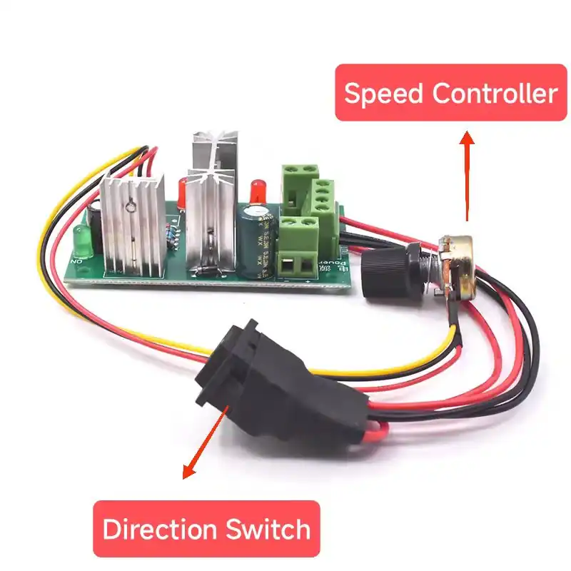
- Reversing Polarity: Simply reversing the polarity of the DC voltage applied to the brushes changes the motor’s direction of rotation.
- H-Bridge Circuit: In electronic control, this is typically achieved through a circuit consisting of four transistors (usually MOSFETs), named for its resemblance to the letter “H.” By switching the two diagonal pairs of transistors (e.g., Q1 and Q4, or Q2 and Q3), the current can be controlled to flow through the motor in either direction, enabling both forward and reverse control.
DC Brushless VS Brushed Motor
The core of the brushed motor is the physical brush-commutator system. The Brushless DC (BLDC) motor, however, is a “flipped” design: the permanent magnets are on the rotor, and the electromagnetic coils are on the stator.
In a brushless dc motor, there are no brushes.
The switching (commutation) of the current in a brushless motor is performed by an external electronic circuit—the Electronic Speed Controller (ESC). The ESC uses transistors to energize the stator coils in a precise sequence, creating a rotating magnetic field that “drags” the permanent magnet rotor to spin.
If you want a comprehensive comparison between Brushless DC Motors (BLDC) and Brushed DC Motors, please click here to read this article:Brushless DC Motors Explained: What They Are, How They Work
Table 3: Brushed DC Motor vs. Brushless DC Motor
| Characteristic | Brushed DC Motor | Brushless DC (BLDC) Motor |
| Commutation Method | Mechanical (Brushes and Commutator) | Electronic (Requires external controller, ESC) |
| Structure | Coils on Rotor, Magnets on Stator | Magnets on Rotor, Coils on Stator |
| Controller Requirement | May require no controller for simple applications | ESC must be used |
| Lifespan | Limited (Constrained by brush/commutator wear) | Extremely long |
| Maintenance | Requires periodic brush replacement and commutator cleaning | Essentially maintenance-free |
| Efficiency | Lower (75-80%) | Higher (85-90%) |
| Speed Range | Lower (Limited by mechanical commutation) | Very high |
| Torque Characteristics | High starting torque | Smooth overall torque |
| EMI (Electromagnetic Interference) | Higher (Due to brush sparking) | Very low |
| Cost | Low motor cost | Higher system cost (Motor + ESC) |
| Typical Applications | Cost-sensitive products, toys, automotive accessories | High-performance applications, drones, electric vehicles, precision instruments |
Applications of Brushed DC Motors
Despite the challenges from new technologies, the brushed DC motor still holds its ground in many fields due to its unique advantages.
Low-Cost Consumer Goods
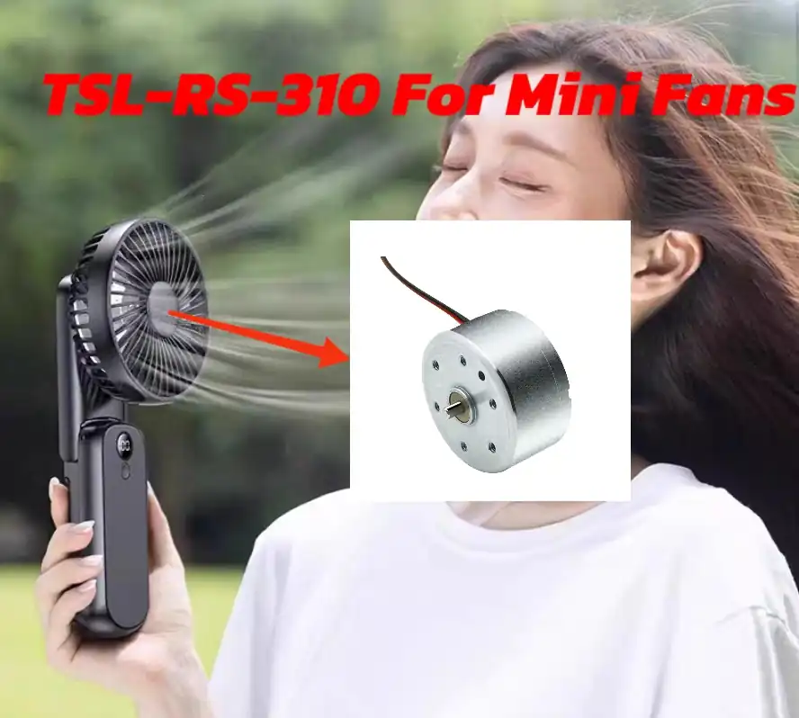
Due to their low cost and simple structure, brushed motors are ubiquitous in applications where performance and lifespan are not critical, such as inexpensive toys, electric toothbrushes, fans, and small kitchen appliances.
Automotive Systems
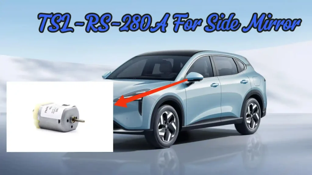
They are widely used for intermittent functions in cars, such as electric windows, power seats, windshield wipers, and starter motors.
Heavy Industry
Their rugged and durable nature is still favored in some high-power, high-torque applications, such as cranes, rolling mills, and paper machines.
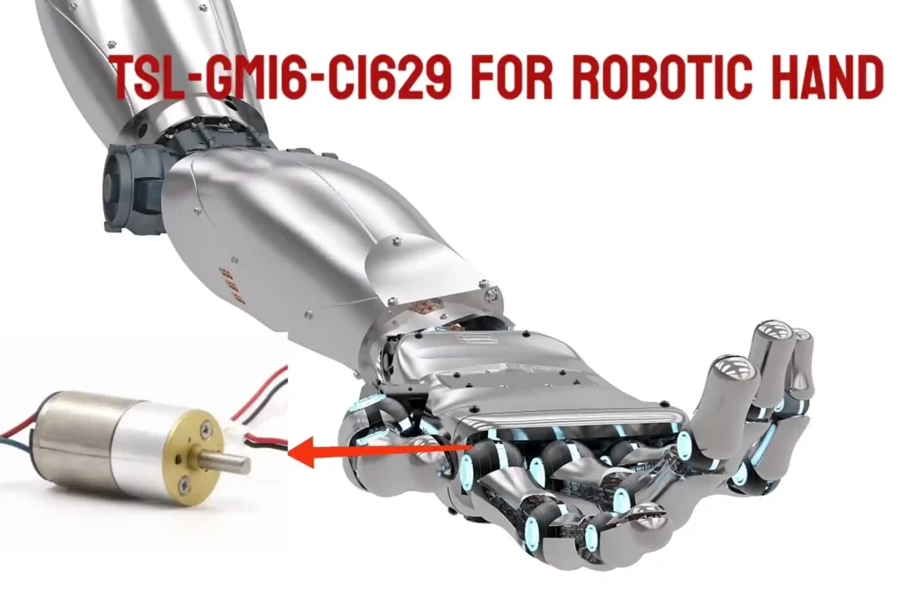
Robotics and Automation
In robotics, especially where high starting torque is needed, brushed motors still find use. High-performance coreless brushed motors are used in fields like humanoid robots and medical prosthetics due to their fast response capability.
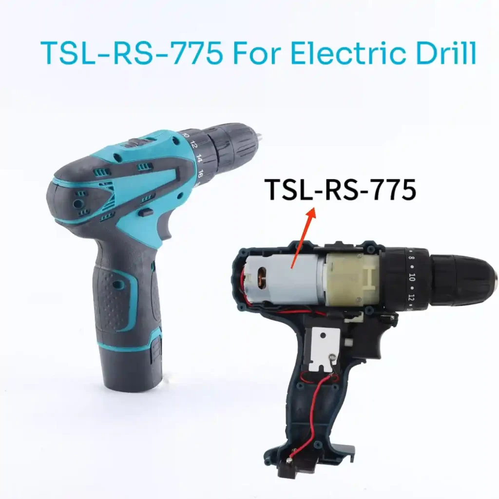
Power Tools
Although the power tool industry is gradually shifting to brushless motors, brushed motors are still widely used in many corded and cordless tools.
All this suggests that the value of the brushed DC motor has shifted from purely performance-based considerations to an economic and engineering trade-off. In almost all performance metrics, the brushless motor is superior.
However, brushed motors are still being mass-produced and used. The fundamental reason is that for a massive number of applications, the combination of the brushed motor’s “good enough” performance and its low cost makes it the optimal engineering choice.
A toy car does not need 90% efficiency or a lifespan of tens of thousands of hours. The enduring success of the brushed motor is a classic lesson in pragmatic engineering economics.
Conclusion
The brushed DC motor defined an era with its elegant mechanical commutation, simple control, high starting torque, and low cost. While newer technologies like the brushless motor have surpassed it in performance, the brushed motor’s unparalleled simplicity and cost-effectiveness ensure it firmly holds its place in the engineering world.
Today, innovations like integrating Artificial Intelligence (AI) and the Internet of Things (IoT) for predictive maintenance in industrial settings are further extending the lifespan and practicality of these classic machines. Therefore, the brushed DC motor should not be viewed as an outdated relic but as a foundational technology. Its basic principles remain relevant today, and its design is itself a masterclass in clever electromechanical problem-solving.
Frequently Asked Questions (FAQ)
Q1: What exactly is a Brushed DC Motor?
A Brushed DC motor is a device that converts DC electrical energy into mechanical energy. It gets its name from its core structure—the “brushes” and the “commutator”—which together are responsible for periodically changing the direction of the current flowing through the rotor coils to produce continuous rotational torque.
Q2: What are the four main components of a Brushed DC Motor?
Stator: The stationary part that produces the fixed magnetic field (usually permanent magnets or field windings).
Rotor/Armature: The rotating part, consisting of winding coils.
Commutator: A mechanical switch mounted on the rotor that periodically reverses the current direction.
Brushes: Stationary conductive contacts that connect the external power source to the rotating commutator.
Q3: What is the main difference between Cored and Coreless motors?
Coreless/Hollow-Cup Motors: Have extremely low rotational inertia, fast response speed, high efficiency, and excellent low-speed smoothness (no cogging torque). However, they have relatively smaller torque and poorer heat dissipation. Suitable for high-precision, fast-response applications (e.g., medical devices, drones).
Cored Motors: Have high rotational inertia and can generate high torque. They have a robust structure and low cost. Suitable for general industrial and household appliance applications.
Tsinglin Motor: Custom DC Motor Solutions
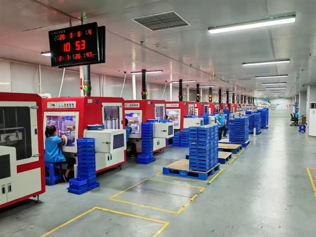
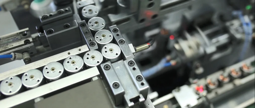
Established in 2009, Tsinglin Motor has evolved into a leading innovator in precision drive systems and specialized motor manufacturing. Our 15,000㎡ advanced production facility in Shenzhen houses a skilled workforce of 200+ professionals, delivering an annual output of 2 million units to global markets.
Continuous R&D investment in energy-efficient motor technologies
Lean manufacturing processes ensuring cost-competitive pricing
Agile production capacity scaling for batch customization
Global compliance certifications (CE, RoHS, REACH)
With dual focus on operational excellence and client success, Twin Motor empowers businesses worldwide to achieve technological differentiation. Our engineering team welcomes complex challenges across automotive, robotics, and smart infrastructure applications.
Contact our solutions center to discuss your project requirements or request our technical portfolio.
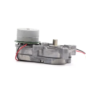
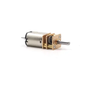
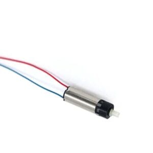
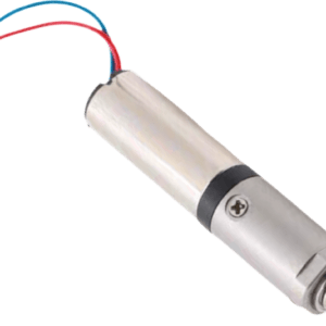
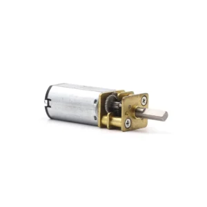
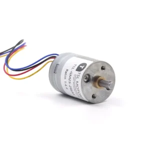
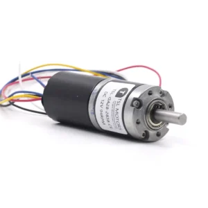
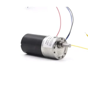
Tsinglin Motor’s Relevant Brushed DC Motor Series
-
 Custom Micro Motors8 products
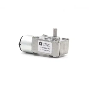
 - DC Gear Motor137 products
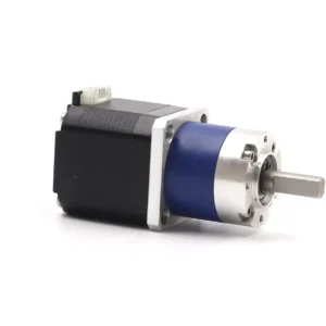
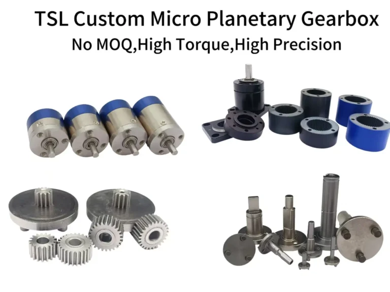
- 6mm Planetary Gear Motor4 products
- 6mm Planetary Metal Gear Motor3 products
- Brushless Gear Motor17 products
- Micro Gear Motor62 products
- Coreless Gear Motor11 products
- N20 Gear Motor26 products
- Plastic Gearbox Motor8 products
- Standard Gear Motor15 products
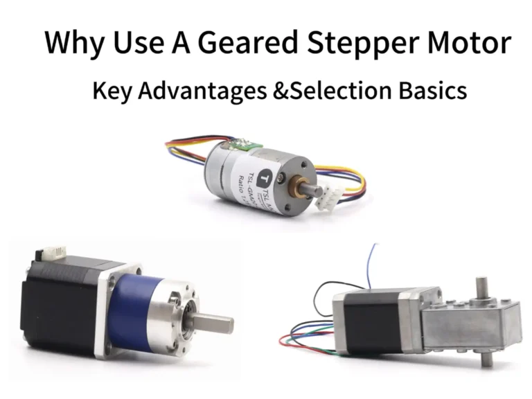
- Stepper Gear Motor13 products
-
- Planetary Gear Motor29 products
- Spur Gear Motor63 products
- Worm Gear Motor28 products
-
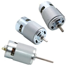
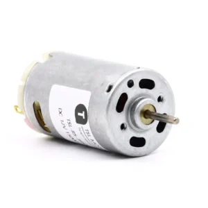
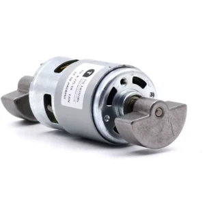
- DC Motor68 products
- Brushed DC Motor16 products
- Brushless DC Motor24 products
- Inrunner Rotor BLDC Motor6 products
- Outrunner Rotor BLDC Motor16 products
-
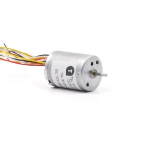
- Coreless DC Motor13 products
- Micro DC Motor15 products
-
- Stepper Motor25 products
- Micro Stepper Motor13 products
- NEMA Stepper Motor9 products
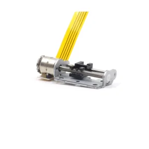
- Stepper Motor Linear Actuator4 products
-
- Vibration Motors71 products
- Brushless Vibration Motor8 products
- Coin Vibration Motor22 products
- Coreless Vibration Motor3 products
- Encapsulated Vibration Motor6 products
- Linear Resonant Actuator12 products
- Powerful Vibrating Motor17 products
- SMD Vibration Motor4 products
- Sonic Vibration Motor2 products
-