Published: OCTOBER 17, 2025
Updated: August 27, 2026
A brushed DC motor converts direct-current electrical energy into rotary mechanical motion. It uses stationary brushes and a segmented commutator to switch current through the rotating armature windings, allowing the motor to produce continuous torque without electronic commutation.
Its operation is simple to understand, but its actual performance depends on the interaction between supply voltage, back electromotive force, winding resistance, armature current and mechanical load. At startup or stall, back EMF is absent and the current can rise far above the normal running value. During continuous operation, winding temperature, brush wear, duty cycle and heat dissipation determine whether the motor can operate reliably.
This article explains the construction and working principle of a brushed DC motor, then examines the electrical, thermal and mechanical limits that matter in practical applications.
Key Takeaways
- Brushes and a segmented commutator mechanically switch the armature current, allowing the rotor to produce continuous torque.
- Motor speed depends mainly on applied voltage, back EMF and load, while torque is approximately proportional to armature current.
- At startup or stall, back EMF is near zero, so current can be several times higher than the normal running current.
- Continuous torque is limited by winding temperature and heat dissipation; stall torque is a short-term limit, not a continuous rating.
- Brush life depends on current, speed, temperature, duty cycle, commutation quality and the frequency of starting and reversing.
What is A Brushed DC Motor?
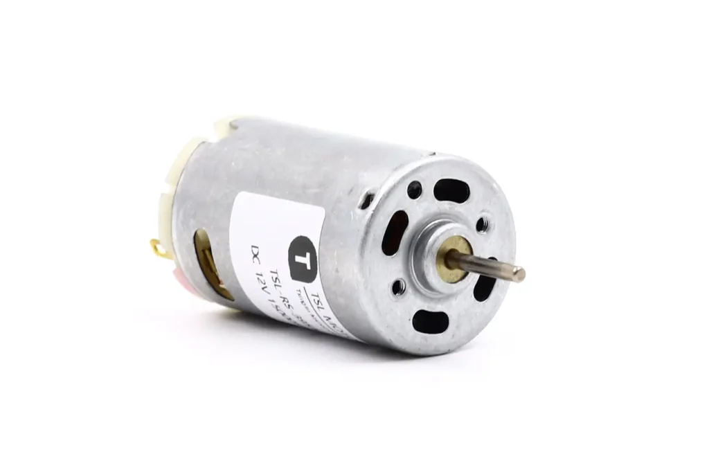
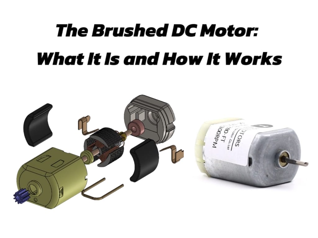
A brushed DC motor is an electromechanical device that converts DC electrical power into rotary motion through mechanical commutation. In the permanent-magnet designs commonly used for small motors, magnets in the stator create a stationary magnetic field, while current flows through the brushes and commutator into the rotating armature windings.
The interaction between the armature current and the stator magnetic field produces torque. As the rotor turns, the segmented commutator changes the electrical connection to the armature windings at the appropriate rotor position, helping the motor continue rotating in the same direction. A basic brushed motor can therefore operate from a suitable DC supply without requiring electronic commutation.
Brushed DC Motor Structure
Most small permanent-magnet brushed DC motors can be explained through four functional assemblies: the stator, rotor or armature, commutator and brushes. A complete motor also includes the shaft, bearings, housing and end cap, which affect alignment, vibration, mechanical load capacity and service life.

Stator
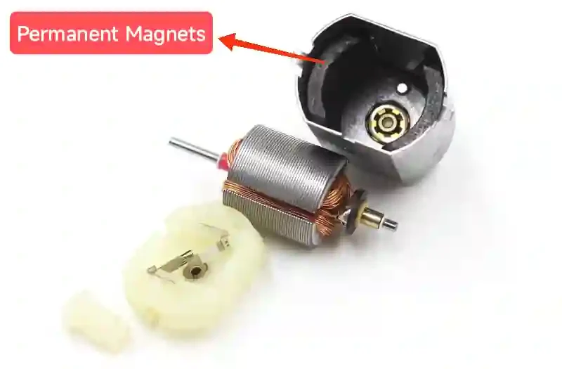
The stator provides the stationary magnetic field. In a permanent-magnet DC motor, magnets are fixed inside the steel housing, which also forms part of the magnetic return path. Wound-field motors use energized field windings instead of permanent magnets.
Magnet strength, air-gap uniformity and magnet alignment affect the torque constant and the current required at a given load. An uneven air gap can also contribute to noise, vibration and inconsistent performance between samples.
Rotor
The rotor is the rotating assembly and normally includes the shaft, armature windings, commutator and, in a conventional design, a laminated iron core. Current flowing through the windings interacts with the stator field to produce torque.
The winding design determines resistance, inductance and the motor’s torque and speed constants. In production, winding consistency, insulation quality, commutator connection and rotor balance directly affect current, temperature rise, vibration and reliability.
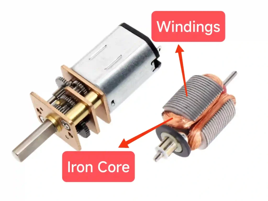
Windings/Coils: Copper wires wound around an iron core. The number of coils and their winding configuration determine the motor’s performance.
Iron Core: The coils are typically wound on a laminated iron core, which not only provides sturdy support for the coils but also helps concentrate the magnetic field and dissipate heat.
Commutator
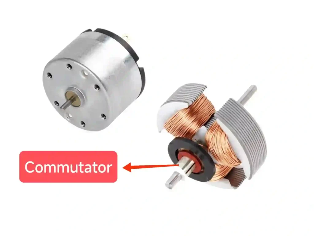
The commutator is a cylindrical assembly of mutually insulated conductive segments mounted on the rotor shaft. Each segment is connected to part of the armature winding.
As the rotor turns, the brushes transfer contact from one segment to the next, changing the current path through the windings. This process is known as mechanical commutation. Segment geometry, surface finish, concentricity and commutation timing influence sparking, electrical noise, torque ripple and brush wear.
Brushes
The brushes are stationary electrical contacts that transfer current from the external circuit to the rotating commutator. Depending on motor size, current and operating conditions, they may use carbon-graphite, metal-graphite or precious-metal contact systems.
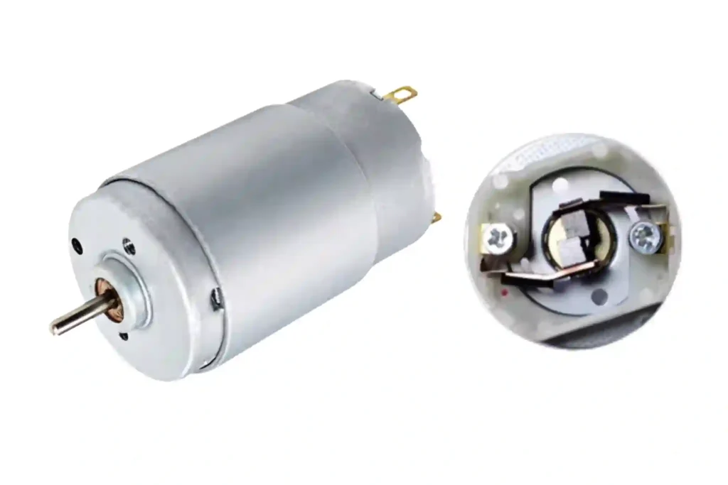
Brush spring force must maintain stable contact without producing excessive friction. Insufficient contact pressure can cause bouncing and arcing, while excessive pressure increases mechanical loss and wear. Brush material therefore cannot be evaluated independently of current, speed, PWM drive conditions and commutator design.
Mechanical commutation is the main structural difference between brushed and brushless motors. For a concise system-level comparison, see Brushless DC vs Brushed Motor: Making the Right Choice.
For available motor sizes, voltages and winding options, visit our brushed DC motor product range.
How Does a Brushed DC Motor Work?
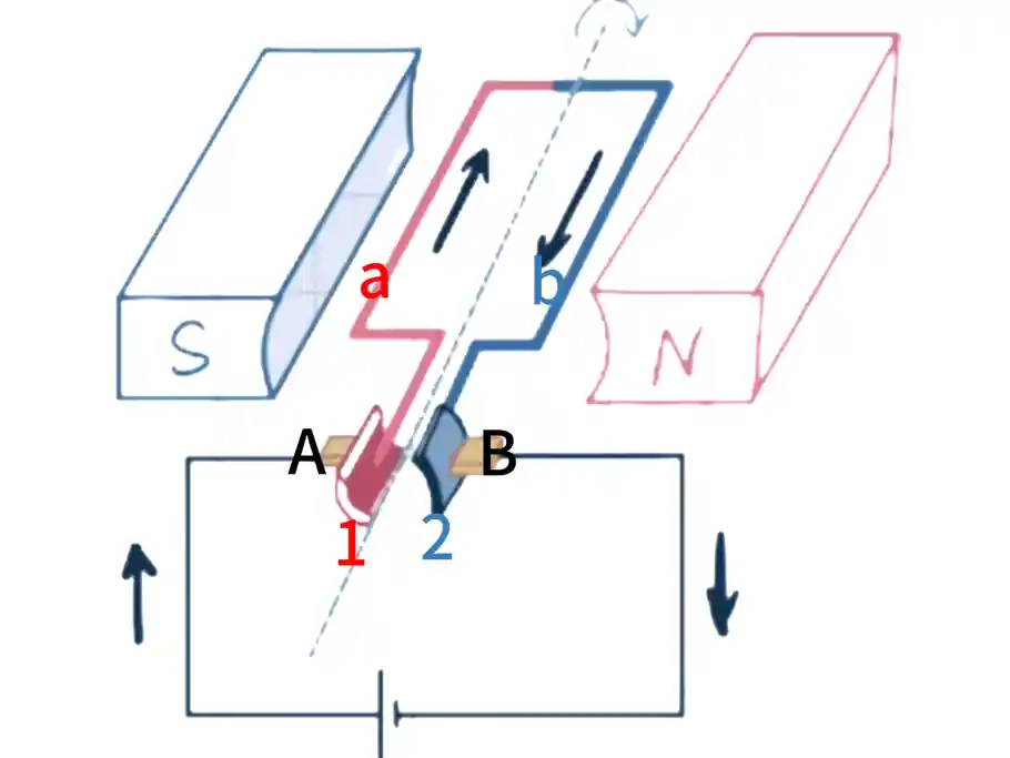
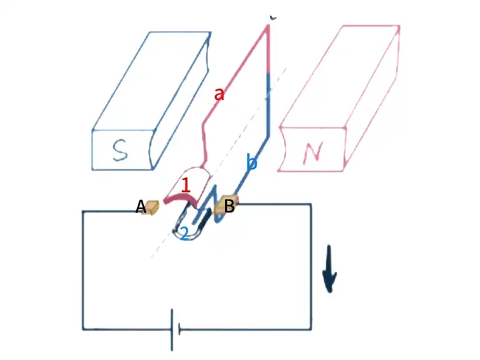
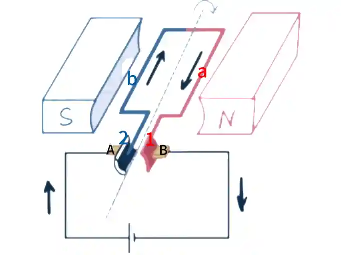
When DC voltage is applied to the motor terminals, current flows through one brush, across the commutator, through the selected armature windings and back through the opposite brush. The energized windings create a magnetic field that interacts with the stator field and produces torque on the rotor.
The brushes and commutator then switch the current path mechanically as the rotor changes position. This keeps the electromagnetic torque acting in the required rotational direction. Unlike a brushless motor, the switching sequence does not require an external rotor-position sensor or electronic commutation circuit.
The Mechanical Commutation Cycle
- Current enters the armature. The brushes contact specific commutator segments and energize the connected windings.
- Electromagnetic torque rotates the rotor. The magnetic field produced by the armature interacts with the stationary stator field.
- The current path changes. As the rotor passes through the commutation region, the brushes move from one commutator segment to the next, changing the current direction in the relevant winding.
- Torque continues in the same rotational direction. The cycle repeats as additional windings are energized and commutated.
Real motors normally use several coils and commutator segments rather than a single coil. More winding sections can reduce torque variation and help the motor start from different rotor positions.
The brushes do not actively measure rotor position. Commutation timing is determined by the mechanical relationship between the brushes, commutator segments and magnetic neutral region. Incorrect brush alignment, commutator eccentricity, surface contamination or excessive current during switching can increase arcing, heat, electrical noise and brush wear.
What Determines Brushed DC Motor Speed, Torque, and Current?
A brushed DC motor does not have one fixed speed or current. Its operating point is established by the supply voltage, winding resistance, back electromotive force, motor constants and mechanical load.
Under steady-state operation, the main electrical relationships can be simplified as:
V = E + I × R + Vbrush
E = kE × ω
T = kT × I
Where:
- V is the voltage measured at the motor terminals;
- E is the back EMF generated by rotation;
- I is the armature current;
- R is the armature winding resistance;
- Vbrush represents the voltage drop across the brush and commutator contacts;
- ω is the rotational speed;
- kE is the back-EMF constant;
- kT is the torque constant.
The torque produced by the motor is approximately proportional to armature current, while back EMF increases with rotational speed. These relationships are also explained in maxon’s motor data reference.
What Happens When the Load Changes?
- At light load, the motor accelerates, back EMF increases and armature current falls to the level needed to overcome friction and the external load.
- When the load increases, speed decreases and back EMF falls. This allows more current to flow, producing additional torque.
- At startup or stall, rotational speed and back EMF are approximately zero. Current is then limited mainly by winding resistance, brush contact drop, wiring and driver impedance.
Winding inductance prevents current from rising instantaneously, but this electrical transient is usually brief in a small motor. If the rotor cannot accelerate, the current approaches the stall-current level:
Istall ≈ (V − Vbrush) / R
Nidec’s explanation of DC motor speed and counter-electromotive force shows the same sequence: higher load reduces speed and back EMF, causing current and torque to increase until a new operating balance is reached.
Practical Engineering Implications
Do not use no-load speed alone to predict performance under load. Two motors with the same rated voltage and external dimensions may use different windings and therefore have different resistance, speed constants, current and torque characteristics.
The driver, power supply, connectors and wiring must tolerate startup and transient current without excessive voltage drop. Actual voltage should be checked at the motor terminals while the motor is loaded, rather than assumed from the power-supply label.
Stall torque represents a zero-speed limit and should not be treated as a continuous operating point. For a more detailed explanation, see Rated Torque vs Stall Torque: Which Value Should Engineers Use?th rotational speed. These relationships are also explained in maxon’s motor data reference.
What Happens When the Load Changes?
- At light load, the motor accelerates, back EMF increases and armature current falls to the level needed to overcome friction and the external load.
- When the load increases, speed decreases and back EMF falls. This allows more current to flow, producing additional torque.
- At startup or stall, rotational speed and back EMF are approximately zero. Current is then limited mainly by winding resistance, brush contact drop, wiring and driver impedance.
Winding inductance prevents current from rising instantaneously, but this electrical transient is usually brief in a small motor. If the rotor cannot accelerate, the current approaches the stall-current level:
Istall ≈ (V − Vbrush) / R
Nidec’s explanation of DC motor speed and counter-electromotive force shows the same sequence: higher load reduces speed and back EMF, causing current and torque to increase until a new operating balance is reached.
Practical Engineering Implications
Do not use no-load speed alone to predict performance under load. Two motors with the same rated voltage and external dimensions may use different windings and therefore have different resistance, speed constants, current and torque characteristics.
The driver, power supply, connectors and wiring must tolerate startup and transient current without excessive voltage drop. Actual voltage should be checked at the motor terminals while the motor is loaded, rather than assumed from the power-supply label.
Stall torque represents a zero-speed limit and should not be treated as a continuous operating point. For a detailed explanation, see Rated Torque vs Stall Torque: Which Value Should Engineers Use?.
Types of Brushed DC Motors
Brushed DC motors can be classified in two independent ways: by how the stator magnetic field is produced and by how the rotating armature is constructed. These classifications should not be confused. For example, a permanent-magnet brushed motor may use either an iron-core or a coreless armature.
Classification by Stator Excitation Method
Permanent Magnet (PMDC) Motors
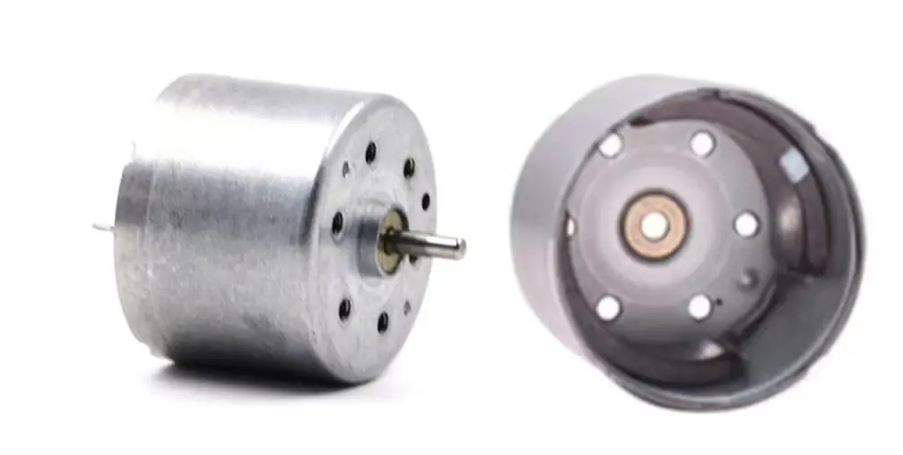
The stator magnetic field is generated by permanent magnets. This is the most common type for small applications, known for its compact structure, reliability, and energy efficiency, as the stator field does not consume electrical power.
Wound-Field Motors
The stator magnetic field is generated by electromagnets (field coils). Based on how the field windings are connected to the armature windings, they are divided into three main subtypes:
- Series-Wound: The field coil is connected in series with the armature. This motor provides very high starting torque, but its speed varies greatly with the load. It is ideal for heavy-duty applications like cranes and winches.
- Shunt-Wound: The field coil is connected in parallel (shunt) with the armature. This motor has good speed regulation, running at a relatively constant speed regardless of load changes.
- Compound-Wound: Combines the characteristics of both series and shunt windings. It offers both high starting torque and good speed stability, suitable for applications requiring both.
Classification by Rotor Structure
Based on the classification by rotor structure, brushed DC motors are categorized into two types: iron-core motors and coreless motors.
Iron-core Motors
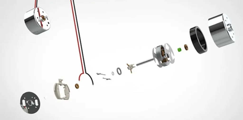
In a conventional iron-core motor, the armature windings are placed in slots around a laminated steel core. The iron core strengthens the magnetic circuit and supports relatively high torque, but it also increases rotor inertia and can introduce cogging and iron losses.
These motors are commonly used in cost-sensitive appliances, automotive mechanisms, toys, pumps and general-purpose actuators. Available models can be found in our iron-core brushed DC motor range.
Coreless Motors
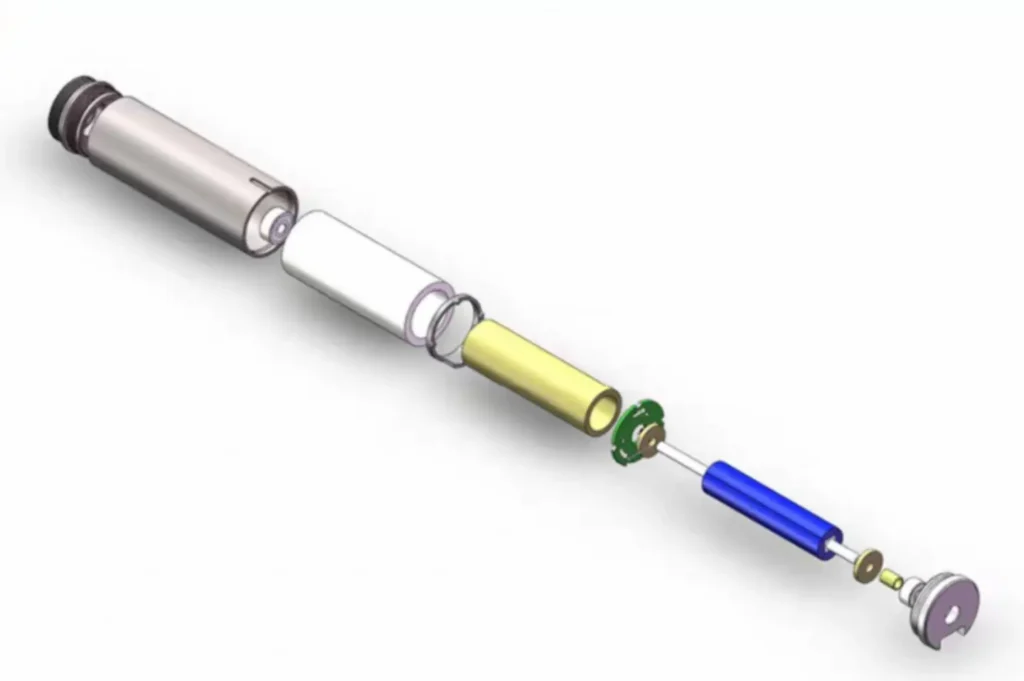
A coreless brushed motor uses a self-supporting cylindrical or basket-shaped winding without a rotating laminated iron core. It still uses brushes and a commutator, but its lower rotor inertia allows faster acceleration and deceleration. Removing the slotted iron armature also eliminates iron-core cogging, helping the motor run smoothly at low speed.
The lightweight winding has less thermal mass, so continuous torque and temperature rise must be checked carefully. Coreless designs are frequently used in medical devices, precision instruments, robotics and compact actuators that require fast dynamic response.
Our coreless DC motor range includes both brushed coreless motors and electronically commutated coreless brushless motors, so the commutation type should be confirmed when comparing products.
Brushed DC Motor Speed and Direction Control
A brushed DC motor can run directly from a suitable DC power source, but practical applications may also require speed adjustment, current limiting or bidirectional operation.
How Is Brushed DC Motor Speed Controlled?
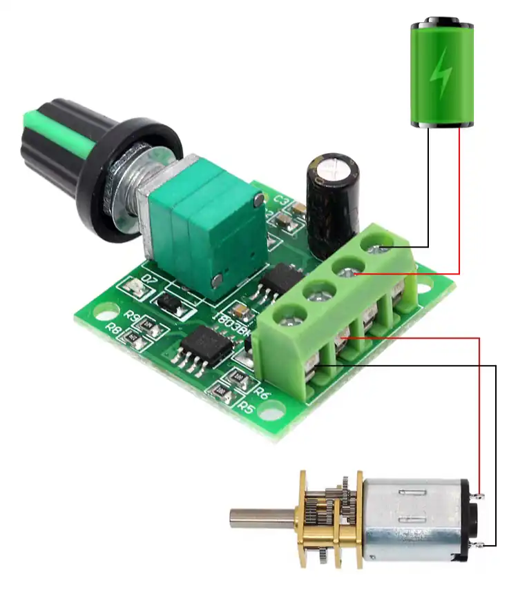
Reducing the voltage at the motor terminals generally reduces its operating speed. However, actual speed under load also depends on back EMF, armature current and mechanical load. Series resistors and linear regulators can reduce voltage, but they dissipate energy as heat.
Pulse-width modulation, or PWM, controls speed by switching the supply voltage rapidly on and off. Changing the duty cycle changes the effective voltage and current delivered to the motor while allowing the switching electronics to operate efficiently.
PWM frequency, motor inductance, winding resistance and back EMF all affect current ripple, noise, heating and brush life. The driver must also provide a suitable path for the winding current when the switching device turns off.
How Is Brushed DC Motor Direction Reversed?
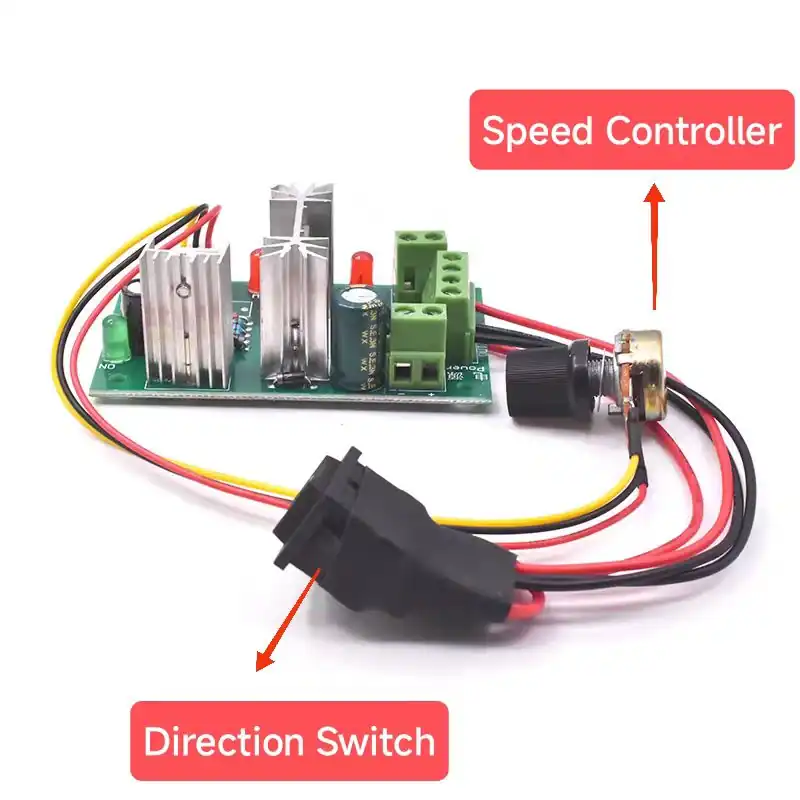
Reversing the polarity applied to the motor terminals reverses the armature current and normally changes the direction of rotation. This can be achieved with a mechanical reversing switch or an electronic H-bridge.
An H-bridge uses four switching devices to apply voltage to the motor in either direction. It may also provide PWM speed control, coasting, braking and current limiting.
Avoid commanding an immediate reversal while the motor is running at high speed unless the driver and mechanical system are designed for it. Rapid reversal can produce high braking current, brush arcing and mechanical shock. Controlled deceleration or current limiting is preferable when frequent reversing is required.
DC Brushless VS Brushed Motor
The fundamental difference is the commutation method. A brushed motor uses brushes and a segmented commutator to switch current mechanically. A brushless DC motor uses an electronic driver to switch current through the stator windings according to rotor position.
| Characteristic | Brushed DC Motor | Brushless DC Motor |
|---|---|---|
| Commutation | Mechanical brushes and commutator | Electronic commutation |
| Typical construction | Windings on the rotor; magnets on the stator | Windings on the stator; magnets on the rotor |
| Controller | Can run directly from a suitable DC supply | Requires a compatible electronic driver |
| Main wear points | Brushes, commutator and bearings | Mainly bearings and other mechanical components |
| Noise and EMI | Brush friction, arcing and electrical noise may occur | No brush arcing, but switching EMI may still occur |
| Typical advantage | Simple control and lower initial system cost | Longer service life, flexible control and potentially higher efficiency |
Neither technology is automatically the best choice for every application. A brushed motor may be the practical solution for simple, intermittent or cost-sensitive equipment. A brushless system is often preferred when long operating life, continuous duty, higher efficiency or advanced speed and torque control justify the additional electronics.
For a more detailed engineering comparison, see Brushless DC vs Brushed Motor: Making the Right Choice. Available sizes and voltage options can also be reviewed in our brushless DC motor product range.
Applications of Brushed DC Motors
Despite the challenges from new technologies, the brushed DC motor still holds its ground in many fields due to its unique advantages.
Low-Cost Consumer Goods
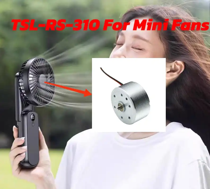
Due to their low cost and simple structure, brushed motors are ubiquitous in applications where performance and lifespan are not critical, such as inexpensive toys, electric toothbrushes, fans, and small kitchen appliances.
Automotive Systems
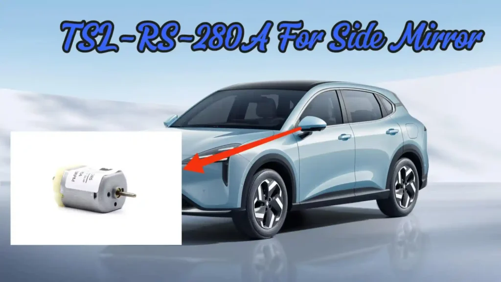
They are widely used for intermittent functions in cars, such as electric windows, power seats, windshield wipers, and starter motors.
Heavy Industry
Their rugged and durable nature is still favored in some high-power, high-torque applications, such as cranes, rolling mills, and paper machines.
Robotics and Automation
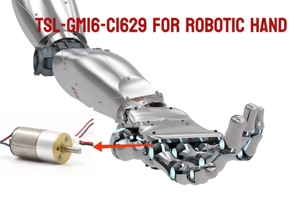
In robotics, especially where high starting torque is needed, brushed motors still find use. High-performance coreless brushed motors are used in fields like humanoid robots and medical prosthetics due to their fast response capability.
Power Tools
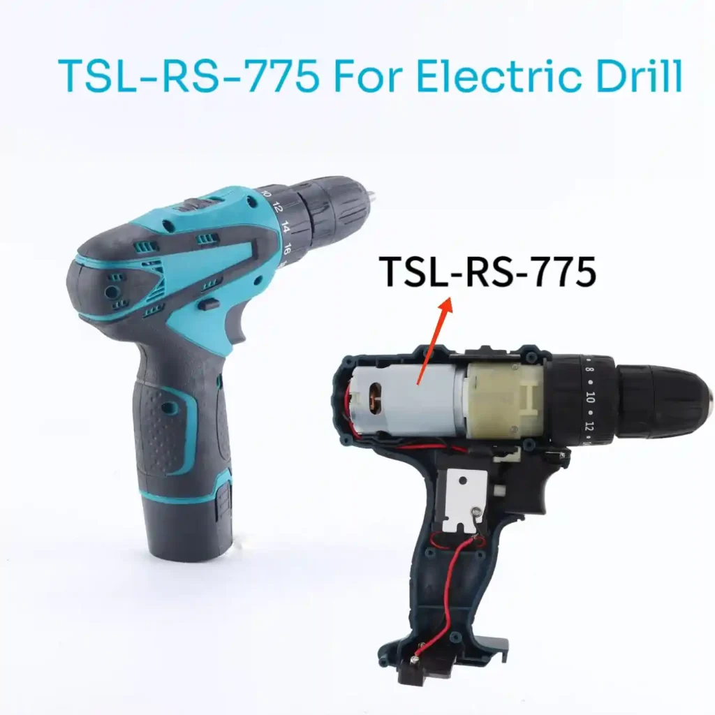
Although the power tool industry is gradually shifting to brushless motors, brushed motors are still widely used in many corded and cordless tools.
All this suggests that the value of the brushed DC motor has shifted from purely performance-based considerations to an economic and engineering trade-off. In almost all performance metrics, the brushless motor is superior.
However, brushed motors are still being mass-produced and used. The fundamental reason is that for a massive number of applications, the combination of the brushed motor’s “good enough” performance and its low cost makes it the optimal engineering choice.
A toy car does not need 90% efficiency or a lifespan of tens of thousands of hours. The enduring success of the brushed motor is a classic lesson in pragmatic engineering economics.
Conclusion
A brushed DC motor uses brushes and a segmented commutator to switch current through the rotating armature windings. This mechanical commutation allows the motor to produce continuous rotation from a suitable DC supply without requiring an electronic commutation system.
Its apparent simplicity does not mean that performance can be judged from voltage or no-load speed alone. Loaded speed, current, continuous torque, startup conditions, duty cycle, temperature rise and brush wear all affect whether the motor can operate reliably in a particular application.
Iron-core brushed motors remain practical for many cost-sensitive and general-purpose mechanisms, while coreless brushed motors offer lower rotor inertia and faster dynamic response. The appropriate choice depends on the actual operating point, required service life, installation environment and total system requirements.
Frequently Asked Questions (FAQ)
Q1: Can a Brushed DC Motor Run Directly from a Battery?
Yes, a brushed DC motor can run directly from a battery if the battery voltage is suitable and the battery can provide the required startup current. A driver is still recommended when the application needs speed control, current limiting, controlled acceleration or bidirectional operation.
Q2: Why Is Startup Current Higher Than Running Current?
At startup, the rotor is stationary and back EMF is approximately zero, so current is limited mainly by winding resistance and the power-supply circuit. As the motor accelerates, back EMF increases and the current falls toward its normal operating value.
Q3: Can a Brushed DC Motor Operate Continuously at Stall Torque?
No. At stall, the shaft speed is zero, back EMF is absent and winding current is usually very high. Stall torque should be treated as a limiting or short-duration condition; continuous operation should be based on the manufacturer’s rated or continuous torque under defined thermal conditions.
Q4: Do All Brushed DC Motors Have an Iron-Core Rotor?
No. Conventional brushed motors normally use windings placed around a laminated iron core, while coreless brushed motors use a self-supporting winding without a rotating iron core. Both types still use brushes and a commutator, but they have different inertia, torque, thermal and manufacturing characteristics.
TSL Motor Brushed DC Motor Solutions
TSL Motor supplies conventional iron-core brushed DC motors, brushed coreless motors and customized motor-and-gearbox assemblies for prototypes and series production. Our in-house motor production, gearbox manufacturing and CNC machining capabilities support both standard products and application-specific modifications.
Available customization options include:
- voltage, winding and loaded-speed adjustment;
- shaft length, diameter, flat sections and output gears;
- sleeve bearings or ball bearings;
- brushes, commutators and EMI-suppression components;
- lead wires, terminals, connectors and cable lengths;
- spur, planetary or worm gearboxes;
- encoders and application-specific mechanical interfaces.
For an initial evaluation, provide the required voltage, loaded speed, continuous torque, peak torque and duration, duty cycle, available installation space, shaft requirements, expected service life and estimated quantity. These details allow the motor, winding and gearbox to be evaluated at the actual operating point.
Samples and small-batch evaluation are available, and many standard models have no minimum order quantity. Contact the TSL Motor engineering team to discuss motor selection, customization or prototype testing.io.