Published: September 17, 2026
The specified backlash of a planetary gearbox might be 15 arcmin, 5 arcmin, or even 1 arcmin. A smaller number generally implies higher reverse positioning capabilities, but without specifying the measurement position, input locking method, and test torque, these parameters cannot be directly compared.
From a gearbox manufacturing perspective, backlash is not merely the clearance between gear teeth. Tooth thickness tolerances of the sun gear, planet gears, and internal ring gear, positional errors of the carrier and planet pins, bearing clearance, component concentricity, and assembly combinations all ultimately manifest at the output end.
Therefore, an engineering backlash requirement should state more than “Backlash ≤ 5 arcmin”. It must specify the test method, operating load, measurement position, state (new vs. end-of-life), and batch acceptance criteria.
Key Takeaways
- Backlash parameters should state the measurement end, input locking method, bidirectional test torque, and angular units.
- Backlash, lost motion, and torsional deformation are distinct parameters; excessive test torque can mix all three into a single reading.
- Planetary gearbox backlash stems not only from tooth flank clearance but also from planet pin positions, bearing clearances, eccentricity, and axial alignment.
- Results from a single position or sample do not represent the full assembly or guarantee mass production capabilities.
- Reducing backlash requires simultaneous control of tooth thickness, center distance, carrier, bearings, concentricity, and selective assembly.
- Increasing encoder resolution enables finer motion observation but cannot eliminate physical gear clearance.
- A backlash target should be derived backward from allowable system end-error, load radius, torque, service life, and cost.
What Exactly Is Planetary Gearbox Backlash?
Backlash describes the angular free play that occurs when the torque direction reverses, as one side of the gear flank disengages before the opposing flank makes contact to transmit torque again. For a complete planetary gearbox, customer focus centers on output-side torsional backlash, expressed in degrees, arcminutes, or arcseconds:
- 1 degree = 60 arcminutes (arcmin)
- 1 arcminute = 60 arcseconds (arcsec)
- 15 arcmin = 0.25 degrees
- 3 arcmin = 0.05 degrees
ISO 21771-2:2025 covers the calculation and measurement of tooth thickness and backlash for involute cylindrical gears, detailing relationships between backlash, tooth thickness, center distance, and profile deviations. Proper backlash is an intentional part of the gear tolerance system, not an accidental defect after assembly.
Standard involute gears without clearance struggle to accommodate lubrication, thermal expansion, profile errors, and assembly variations. The engineering objective is controlling the target backlash range and batch consistency under operating conditions.
What Is the Difference Between Backlash, Lost Motion, and Torsional Stiffness?
| Parameter | Engineering Meaning |
| Backlash | Free angular displacement caused by mechanical clearance during flank reversal. |
| Lost Motion | Total angular lag measured when reversing direction under load, combining clearance and structural displacement. |
| Torsional Stiffness | Transmission system resistance to elastic torsion after tooth flanks are fully loaded. |
In physical testing, lost motion may simultaneously include:
- Gear flank clearance
- Bearing clearance
- Micro-displacements between planet pins and carrier
- Shaft and output shaft torsion
- Elastic gear tooth deformation
- Housing and mounting structure deformation
Lost motion cannot be treated as pure tooth flank backlash. Pure mechanical clearance is a component of lost motion; higher test torques increase the proportion of elastic deformation in the reading.
Why Must Test Torque Be Included in Specifications?
Planetary gearbox backlash cannot be measured meaningfully without specifying the torque applied during the test.
A common method is to lock the gearbox input, apply a defined clockwise torque to the output, record the angular position, and then repeat the process in the opposite direction.
If the applied torque is too low, grease resistance, seal friction and bearing friction may prevent the gear teeth from reaching stable contact on both flanks. The measured result may therefore understate the actual reverse clearance or vary significantly between tests.
If the applied torque is too high, the reading begins to include:
- Gear-tooth elastic deformation;
- Shaft torsion;
- Bearing displacement;
- Planet-carrier deformation;
- Fixture and coupling compliance.
The result is no longer pure free clearance. It becomes a combination of backlash and load-dependent lost motion.
This is why manually twisting the output shaft and describing the movement as “backlash” is not sufficient for precision evaluation. A repeatable test must define:
- How the input is locked;
- Clockwise and counterclockwise test torque;
- Measurement temperature;
- Lubrication and break-in condition;
- Output measurement position;
- Number of measurement points;
- Measurement instrument and fixture.
A reported value such as “10 arcmin backlash” is incomplete unless these test boundaries are known.
Why Is a Hysteresis Curve More Useful Than One Backlash Number?
A single backlash value shows the angular difference between two selected contact states. A torque–angle hysteresis curve shows what happens throughout the complete loading, unloading and reversal process.
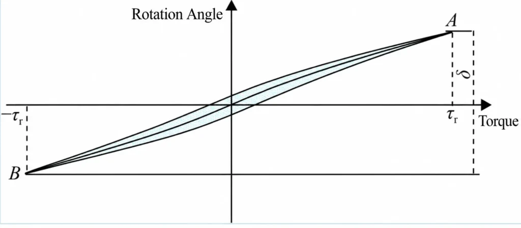
The test normally follows this sequence:
- Lock the gearbox input.
- Apply clockwise torque to the output.
- Record torque and angular displacement.
- Gradually remove the torque.
- Apply counterclockwise torque.
- Record the reverse loading curve.
- Return to the unloaded condition.
Near the reversal region, the curve reflects gear clearance, friction and the transition from one tooth flank to the opposite flank. Once the gears are fully loaded, further angular displacement is increasingly influenced by elastic deformation.
Torsional stiffness can be estimated from the loaded portion of the curve:
Torsional stiffness = Change in torque ÷ Change in torsional angle
Ct = ΔT ÷ Δφ
Where:
- Ct is torsional stiffness;
- ΔT is the change in torque;
- Δφ is the corresponding change in angular displacement.
Backlash and torsional stiffness therefore describe different mechanical behaviors. A gearbox may have low free clearance but still deform noticeably under load. Conversely, a stiff gearbox may still contain measurable tooth clearance during reversal.
Research on low-backlash planetary gearbox design and hysteresis testing also uses torque–angle behavior to evaluate backlash and torsional stiffness. This method is more informative than treating every measured angular displacement as tooth clearance alone.
A hysteresis curve does not automatically separate every source of error, but it provides much more diagnostic information than one angular value measured at an arbitrary torque.
How to Build a Repeatable Backlash Test Fixture
A micro planetary gearbox can be measured using an output-side angular encoder or a rigid measurement arm attached to the output shaft.
A practical test fixture should include:
- A rigid input-locking device;
- A stable gearbox mounting base;
- An output arm with a known effective radius;
- A controlled bidirectional torque source;
- An angular encoder, dial indicator or displacement sensor;
- A method for recording temperature and test conditions.
The fixture’s own clearance and deformation must be substantially smaller than the backlash being evaluated. Otherwise, the result may describe the fixture rather than the gearbox.
Couplings, shaft clamps, adapters and measurement arms should be checked separately. Even a small amount of play in one connection can significantly distort the result when testing a micro gearbox.
Converting Linear Displacement into Arcminutes
If a displacement sensor measures total tangential movement s at an effective radius r, the corresponding angle is:
θ = arctan(s ÷ r)
The result can be converted into arcminutes:
Backlash in arcmin = arctan(s ÷ r) × 180 ÷ π × 60
For small angular displacements, the following approximation is normally sufficient:
Backlash in arcmin ≈ 3437.75 × s ÷ r
The displacement s and radius r must use the same unit.
For example:
- Measurement radius = 100 mm;
- Total bidirectional displacement = 0.30 mm.
The estimated angular movement is:
Backlash ≈ 3437.75 × 0.30 ÷ 100
Backlash ≈ 10.3 arcmin
Before fixture compliance and test-torque effects have been separated, it is more accurate to report this result as:
Output lost motion measured under a specified bidirectional test torque.
This wording avoids presenting every measured displacement as pure gear-tooth backlash.
Why Measure Multiple Angles and Both Reversal Directions?
Backlash is rarely identical at every angular position of a planetary gearbox.
Variation can be caused by:
- Sun-gear eccentricity;
- Planet-gear tooth variation;
- Ring-gear runout;
- Carrier machining error;
- Planet-pin position error;
- Bearing clearance;
- Shaft misalignment;
- Housing concentricity;
- Uneven load sharing between planets.
At minimum, measurements should be taken at:
- 0 degrees;
- 90 degrees;
- 180 degrees;
- 270 degrees.
Higher-precision applications should use more positions around the complete output revolution.
At every position, both reversal directions should be recorded:
- Clockwise to counterclockwise;
- Counterclockwise to clockwise.
Several repeated measurements should also be made at each position. For acceptance testing, the maximum measured value per unit is usually more meaningful than the average alone.
If the two reversal directions produce substantially different results, inspect:
- Load orientation;
- Output-bearing play;
- Carrier offset;
- Fixture alignment;
- Coupling clearance;
- Torque-application symmetry.
Testing only one output angle can miss a local maximum caused by eccentricity or accumulated manufacturing tolerances.
Where Does Planetary Gearbox Backlash Originate?
A planetary gearbox contains an external mesh between the sun and planet gears and an internal mesh between the planet gears and ring gear. Multiple planet gears, pins and carrier features make its tolerance chain more complex than that of a single external gear pair.
Readers who need to review the sun gear, planet gears, ring gear and carrier load path can first see What Is a Planetary Gear Motor? Design & Working Principle. The planetary arrangement explains why output backlash is influenced by several simultaneous gear meshes rather than one isolated gear pair.

| Backlash or lost-motion source | Possible effect |
|---|---|
| Sun-gear tooth thickness | Changes sun-to-planet clearance |
| Planet-gear tooth thickness | Influences both external and internal meshes |
| Ring-gear tooth profile and thickness | Changes planet-to-ring clearance |
| Operating center distance | Alters tooth contact and running clearance |
| Gear eccentricity and runout | Causes backlash to vary with output angle |
| Planet-pin position error | Produces uneven contact timing and load sharing |
| Bearing clearance | Allows relative movement between shafts, gears and carrier |
| Carrier machining error | Changes planet centers and branch alignment |
| Shaft and housing concentricity | Produces localized tooth contact |
| Lubrication condition | Influences friction and measured contact transition |
| Gear and bearing wear | Increases clearance during service life |
Reducing backlash is therefore not simply a matter of increasing gear-tooth thickness. If tooth clearance is reduced without controlling the carrier, center distance, bearings and ring-gear concentricity, the gearbox may develop localized tight spots rather than stable low backlash.
Gear material and manufacturing method also influence dimensional consistency, wear and the tooth accuracy that can be maintained in production. These differences are compared in Micro Planetary Gearbox: Materials, Sizes and Selection.
Is Lower Backlash Always Better?
No. The correct target is not the smallest possible number. It is the lowest backlash that can be manufactured reliably while preserving lubrication, efficiency, temperature margin and service life.
Excessively reducing gear clearance can cause:
- Localized tight mesh;
- Higher friction;
- Increased operating temperature;
- Greater sensitivity to lubricant viscosity;
- Reduced mechanical efficiency;
- Accelerated wear;
- Lower assembly yield;
- Interference after thermal expansion;
- Inconsistent performance between production batches.
Backlash should also be considered together with ratio, tooth count, gear module and the number of stages. A ratio that is mathematically possible may still create an impractical sun gear, insufficient tooth strength or an unfavorable tolerance chain. These limits are explained in Planetary Gearbox Gear Ratio: Custom Design & DFM Limits.
The term “low backlash” also has no universal threshold across all gearbox sizes.
A backlash value achieved by a large industrial precision gearbox cannot be transferred directly to a micro planetary gearhead. Frame diameter, torque range, bearings, gear module, manufacturing process and test torque may be completely different.
The practical rule is:
Backlash should be low enough to meet the application’s output-position requirement, but not lower than the manufacturing process and operating conditions can support reliably.
How Can Backlash Be Reduced and Stabilized in Production?
Control Gear Geometry
Tooth thickness, pitch deviation, profile error and runout must be controlled together. Improving only one dimension rarely stabilizes the final gearbox.
Increasing tooth thickness without correcting center distance or runout can reduce clearance at one rotational position while creating binding at another.
Control Center Distance and Planet-Pin Position
Carrier-hole spacing, pin diameter and pin installation position determine how evenly the planetary branches contact and share load.
If one planet contacts earlier than the others, it may carry a disproportionate share of the load. The gearbox may pass a low-load backlash test but develop uneven wear under working torque.
Control Ring-Gear and Carrier Concentricity
Ring-gear eccentricity can make backlash change as the output rotates. A gearbox may meet the requirement at one angle and exceed it at another.
This is one reason why checking only one angular position is insufficient for a precision gearbox.
Control Bearings, Shafts and Housing Fits
Bearing clearance, shaft fits and housing concentricity contribute to total output movement. These interfaces must be included in the complete mechanical tolerance chain.
A gearbox with accurately machined gears can still show excessive lost motion if the output bearing, planet pins or housing fits are not controlled.
Use Selective Assembly
Even components that meet their drawing tolerances still contain dimensional variation. Randomly assembling them can produce a wide distribution of finished backlash.
Selective assembly measures and groups components before matching suitable sets:
Measure components → Classify dimensions → Match suitable sets → Assemble → Verify output backlash
Useful matching characteristics can include:
- Gear-tooth thickness;
- Over-pin measurement;
- Ring-gear internal dimensions;
- Planet-pin diameter;
- Carrier-hole position;
- Bearing and shaft fits.
Selective assembly cannot replace accurate components, but it can reduce the variation created by random tolerance stacking.
It also cannot compensate for an unsuitable basic gearbox structure. When the required backlash, ratio, output shaft or bearing arrangement exceeds the adjustment range of an existing platform, the project may need a custom planetary gearbox rather than additional screening of standard units.
Apply Preload Carefully
Preload can reduce apparent free movement in certain transmission structures, but it also increases friction, heat and sensitivity to dimensional error.
For a conventional micro planetary gearbox, preload is not a universal route to zero backlash. It must be validated for:
- Starting torque;
- Efficiency;
- Operating temperature;
- Lubrication;
- Wear;
- Service life.
How Do Multiple Stages and Wear Affect Backlash?
A multi-stage planetary gearbox contains additional:
- Gear meshes;
- Planet carriers;
- Pins;
- Bearings;
- Shafts;
- Dimensional tolerance chains.
However, the backlash values of individual stages should not simply be added as output arcminutes. Angular movement generated in an earlier stage is transformed by the reduction ratio of the following stages.
The most reliable verification method is to measure the fully assembled gearbox at its final output.
Component inspection remains necessary for manufacturing control, but finished-assembly testing determines whether the delivered gearbox meets the application requirement.
The effect of stage count should also be evaluated together with efficiency and torque loading. The 28 mm planetary gearbox 27:1 engineering example shows why the finished operating point cannot be determined from nominal ratio alone.
Backlash may also change during operation because of:
- Tooth-flank wear;
- Bearing wear;
- Planet-pin fit changes;
- Lubricant migration;
- Repeated shock loading;
- Contamination;
- Thermal cycling.
Positioning applications should distinguish between:
- Initial backlash;
- Post-break-in backlash;
- Post-endurance backlash;
- Expected end-of-life backlash.
A new gearbox measuring 5 arcmin does not automatically remain at 5 arcmin throughout its intended service life.
Backlash should therefore be treated as a life-cycle variable. A NIST study of robot-joint degradation identifies gear backlash and bearing friction as important degradation mechanisms that can affect joint position, velocity and torque behavior.
Why Does a Golden Sample Not Prove Production Capability?
A prototype that measures 8.2 arcmin proves that one unit achieved that result under one set of test conditions.
It does not prove that serial production can consistently maintain a maximum limit of 10 arcmin.
A meaningful batch record should include:
- Product model and gear ratio;
- Unit serial or batch number;
- Defined test torque;
- Measurement positions;
- Clockwise-to-counterclockwise results;
- Counterclockwise-to-clockwise results;
- Maximum value for each unit;
- Temperature and lubrication condition;
- Break-in status;
- Fixture and operator identification;
- Batch mean and standard deviation;
- Pass rate;
- Trend toward the upper specification limit.
Three to five engineering samples can demonstrate design feasibility, but they are not sufficient to prove stable serial-production capability.
ISO 22514-3:2020 states that its machine-performance methods are not considered suitable for fewer than 30 observations. Even with a larger sample, a process-capability result remains meaningful only when the measurement system and production process are stable.
A sensible validation sequence is:
Engineering samples → Pilot-run distribution → Measurement-system analysis → Batch monitoring → Process-capability evaluation
The gearbox design and production process should therefore be evaluated separately. A good prototype is the beginning of validation, not the end.
Fifteen Arcminutes Is a Specification Limit, Not a Batch Report
The standard TSL Motor GIM4315-40 planetary robotic joint module provides a useful example.
| Parameter | TSL Motor GIM4315-40 |
|---|---|
| Gearbox type | Planetary gearbox |
| Gear ratio | 40:1 |
| Gear material | Steel |
| Gearbox backlash | 15 arcmin |
| Onboard encoder | 14-bit |
| Secondary output encoder | Supported |
| Rated torque | 15.50 N·m |
| Peak torque | 45.41 N·m |
| Rated output speed | 20 rpm |
The listed 15 arcmin value is a product specification limit. It does not mean that every manufactured unit measures exactly 15 arcmin.
A batch report should show the actual measurements and their distribution within the acceptance limit.
The 14-bit encoder also does not eliminate mechanical clearance. If the encoder is installed on the motor side, it measures rotation before the planetary gearbox. An output-side encoder can measure the actual output position, but it still does not physically remove clearance between the gears.
This distinction is particularly important in brushless closed-loop systems. The motor, gearbox, encoder and controller should be evaluated as one drive system. The main integration factors—including loaded speed, output torque, feedback position, duty cycle and temperature—are covered in Brushless Planetary Gear Motor: Features & Selection Guide.
Engineers comparing alternative diameters, motor types and reduction-ratio ranges can also review the broader TSL Motor planetary gear motor range.
How Should a Realistic Backlash Target Be Defined?
A backlash target should be derived from the system error budget instead of copied from a supplier catalogue.
The design review should consider:
- Allowable bidirectional error at the load;
- Effective load radius;
- Gearbox share of the total error budget;
- Continuous and peak output torque;
- Reversal frequency;
- Duty cycle;
- Working temperature;
- Lubrication condition;
- Required operating life;
- Motor-side or output-side feedback;
- Software-compensation capability;
- New and post-endurance performance.
If an application can tolerate 20 arcmin, specifying 1 arcmin may add unnecessary machining, inspection, selective assembly and development costs.
If the system requires less than 3 arcmin of mechanical free play, a standard 15 arcmin platform cannot meet that requirement merely by increasing encoder resolution.
The required backlash must also be evaluated with the selected reduction ratio and number of stages. A higher ratio may reduce output speed and increase theoretical torque multiplication, but it can introduce additional gear meshes and a longer tolerance chain. Ratio feasibility can be checked through the planetary gearbox custom ratio and DFM guide.
Recommended Backlash Specification
| Item | Recommended definition |
|---|---|
| Backlash limit | ≤ X arcmin |
| Measurement point | Final output shaft or flange |
| Input condition | Mechanically locked |
| Reverse test torque | Defined positive and negative output torque |
| Temperature | Nominal value and allowable range |
| Gearbox condition | New, broken-in or post-endurance |
| Measurement positions | Minimum number per output revolution |
| Reversal directions | CW to CCW and CCW to CW |
| Acceptance value | Maximum value per unit |
| Service-life requirement | Maximum backlash after defined hours or cycles |
| Batch acceptance | Sampling plan or 100% inspection |
When Is a Custom Low-Backlash Platform Necessary?
A custom platform becomes necessary when the required backlash cannot be achieved reliably by screening or selectively assembling components from an existing gearbox.
Possible development work includes:
- Revising gear-tooth thickness and profile tolerances;
- Matching sun, planet and ring gears;
- Improving carrier machining;
- Tightening planet-pin position tolerances;
- Changing bearing clearance or preload;
- Optimizing operating center distance;
- Improving ring-gear-to-housing concentricity;
- Developing a dedicated test fixture;
- Defining test torque and measurement positions;
- Creating selective-assembly groups;
- Validating break-in and endurance behavior;
- Establishing batch acceptance criteria.
These requirements should be confirmed before quotation and tooling. Otherwise, the project may encounter unexpected cost, low assembly yield or extended validation time.
A standard gearbox can often be modified successfully, but very low backlash may require a different gear module, bearing arrangement, machining process or housing structure. The practical limit depends on:
- Gearbox diameter;
- Reduction ratio;
- Continuous and peak torque;
- Duty cycle;
- Operating temperature;
- Required lifetime;
- Production quantity.
For very small brushless drive systems, gearbox backlash must also be evaluated with motor control, encoder location, wiring space and thermal limits. These integration issues are covered in Micro Brushless Planetary Geared Electric Motor Customization.
Essential Elements of a Backlash Test Report
| Report field | Engineering purpose |
|---|---|
| Model and gear ratio | Identifies the tested configuration |
| Serial or batch number | Provides traceability |
| Fixture ID | Identifies the measurement system |
| Input-locking method | Defines the boundary condition |
| Bidirectional test torque | Makes results comparable |
| Temperature and lubrication | Records friction and dimensional conditions |
| Break-in status | Defines the gearbox running condition |
| Measurement positions | Confirms angular coverage |
| CW-to-CCW results | Records one reversal direction |
| CCW-to-CW results | Detects directional asymmetry |
| Maximum backlash per unit | Provides the primary acceptance value |
| Batch mean and standard deviation | Shows process centering and variation |
| Measurement uncertainty | Establishes confidence in the result |
| Operator and test date | Supports process traceability |
| Post-endurance result | Evaluates wear-related change |
A report that states only “Backlash: PASS” is insufficient for engineering comparison or long-term process monitoring.
Recommended Validation Workflow
- Define the allowable backlash from the system error budget.
- Specify the output measurement point.
- Define the input-locking method.
- Define the positive and negative test torque.
- Validate fixture rigidity and sensor resolution.
- Apply forward torque and record the stable output angle.
- Apply reverse torque and record the opposite contact position.
- Calculate the angular difference.
- Repeat the test at multiple output angles.
- Record both reversal directions.
- Evaluate measurement repeatability on the same unit.
- Test multiple units to examine batch variation.
- Repeat testing after break-in or endurance operation.
- Validate the gearbox inside the actual mechanism.
Common Measurement Mistakes
| Mistake | Why it produces a misleading result |
|---|---|
| Twisting the output by hand | Applied torque is uncontrolled |
| Holding the motor electronically | Controller stiffness affects the measurement |
| Testing only one output angle | Local runout or eccentricity may be missed |
| Applying excessive torque | Elastic deformation is counted as backlash |
| Applying insufficient torque | Friction may prevent full flank contact |
| Ignoring coupling clearance | Fixture play is attributed to the gearbox |
| Reporting only the average | Worst-case positions and outliers are hidden |
| Testing one golden sample | Production variation is not evaluated |
| Calling all movement backlash | Bearing and structural deformation are included |
| Comparing catalogue values directly | Test methods and torque conditions may differ |
| Demanding the smallest possible value | Cost, friction and binding risk increase |
| Increasing encoder resolution | Measurement resolution does not remove clearance |
FAQ
How should planetary gearbox backlash be measured?
Lock the input shaft, apply a specified clockwise and counterclockwise torque to the output, and measure the angular difference between the two stable tooth-contact states. Precision testing should cover multiple output positions and both reversal directions.
Are backlash and lost motion the same?
No. Backlash mainly refers to mechanical clearance between mating components. Lost motion may also include bearing displacement, shaft torsion, gear deformation, carrier flex and housing compliance.
Why does backlash vary between units in the same batch?
Every sun gear, planet gear, ring gear, carrier, pin, bearing and housing contains manufacturing variation. These tolerances combine differently in each assembly, producing a distribution rather than one identical value.
Is lower backlash always better?
No. The required value should match the application’s positioning tolerance while preserving sufficient margin for lubrication, thermal expansion, manufacturing variation and wear.
Can software eliminate gearbox backlash?
Software can compensate for a stable and repeatable directional offset, especially when output feedback is available. It cannot physically remove gear clearance or fully correct load-dependent deformation.
Can a high-resolution encoder eliminate mechanical backlash?
No. An encoder measures movement at its installation point. A motor-side encoder cannot directly observe gearbox clearance. An output encoder can detect actual output position, but it cannot remove the physical gap between mating components.
Should average or maximum backlash be used for acceptance?
For positioning-critical applications, the maximum measured value per unit is normally the safer acceptance metric. Average values can hide local angular peaks and individual outliers.
Conclusion
Planetary gearbox backlash cannot be evaluated from an arcminute value alone. Test torque, input restraint, fixture rigidity, output position, temperature, lubrication and measurement uncertainty all influence the result.
Stable low backlash depends on the complete tolerance chain:
- Gear geometry;
- Operating center distance;
- Planet-pin position;
- Carrier accuracy;
- Bearing clearance;
- Shaft and housing concentricity;
- Lubrication;
- Selective assembly;
- Finished-output testing.
The required specification should be derived from the application’s allowable output error, effective load radius, working torque, reversal frequency and service-life target. Selecting the smallest catalogue value without defining the test conditions can increase cost without guaranteeing better system positioning.
Engineers can first compare available diameters, motor technologies and ratio ranges in the TSL Motor planetary gear motor range. If the standard ratio, shaft, bearing arrangement or backlash range cannot meet the application, the next step is to define the measurement method and evaluate a custom planetary gearbox solution.