Published: NOVEMBER 21, 2025
Updated:SEPTEMBER 2, 2026
A planetary gear motor combines an electric motor with a planetary gearbox to reduce speed and deliver higher output torque in a compact, coaxial package. In the most common arrangement, the motor drives the central sun gear, the ring gear remains fixed, and the planet carrier becomes the gearbox output.
The load is transmitted through several planet gears, but this structure does not automatically guarantee a specific torque, efficiency, backlash or service life. Actual performance depends on the gear ratio, number of stages, gear material, tooth accuracy, lubrication, bearing support, motor characteristics and operating duty.
This article explains how a planetary gear motor works, its main components and the engineering limits behind its commonly stated advantages. Engineers looking for available diameters, voltages and motor combinations can review our planetary gear motor range.
Key Takeaways
- In the most common planetary arrangement, the motor drives the sun gear, the ring gear remains fixed, and the planet carrier provides the reduced-speed output.
- Several planet gears share the transmitted load, but actual torque capacity still depends on gear accuracy, materials, bearing support and load distribution.
- The total reduction ratio of a multi-stage gearbox is calculated by multiplying the ratio of each stage. Additional stages also increase length and mechanical losses.
- Estimated output torque depends on motor torque, reduction ratio and gearbox efficiency, but it must not exceed the gearbox’s continuous or intermittent torque rating.
- Planetary gearboxes can be combined with brushed, brushless, coreless or stepper motors. The motor type changes control, speed, efficiency and service life, not the basic planetary transmission principle.
- Selection should begin with loaded output speed and continuous output torque, followed by duty cycle, backlash, radial and axial loads, operating temperature and installation space.
Planetary Gear Motor Components and Structure
A planetary gear motor combines an electric motor with a planetary gearbox in one drive unit. The motor produces rotary motion, while the gearbox reduces the output speed and increases the available output torque. Because the input and output shafts can remain on the same axis, this arrangement is useful when the installation diameter and alignment are tightly constrained.

Main Components
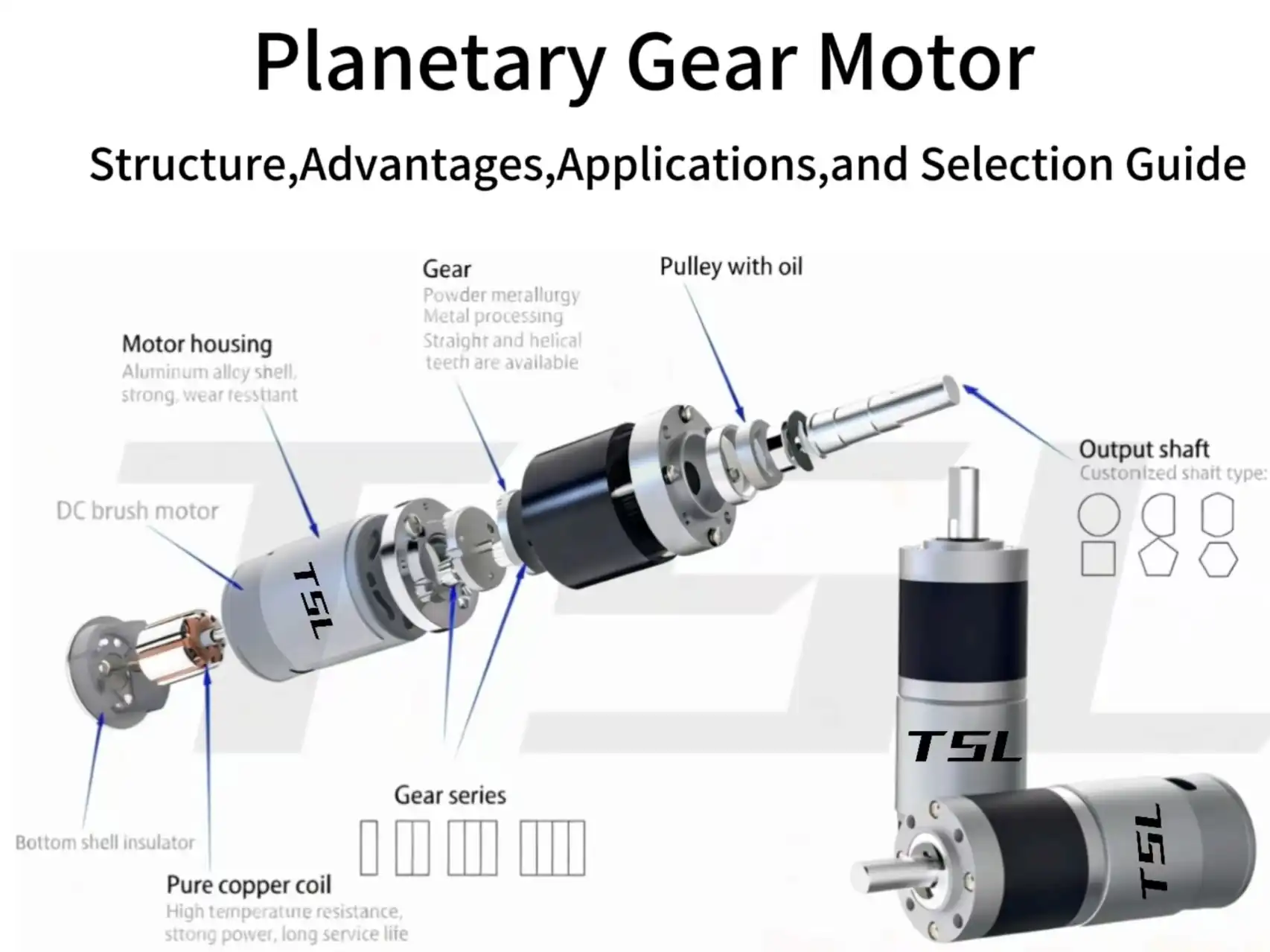
A typical planetary gear motor includes:
- Electric motor: Provides the input speed and torque. Depending on the application, it may be a brushed DC, brushless DC, coreless or stepper motor.
- Sun gear: The central gear, normally connected to the motor shaft or an input pinion.
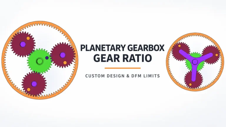
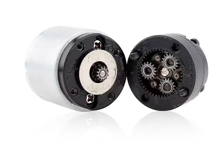
- Planet gears: Several gears that mesh with both the sun gear and the internal ring gear.
- Ring gear: An internally toothed outer gear that is commonly fixed to the gearbox housing.
- Planet carrier: Supports the planet gears and, in the common reduction arrangement, transfers their orbital motion to the output shaft.
- Housing, bearings and output shaft: Maintain gear alignment and support external radial and axial loads.
In the common configuration used in compact gear motors, the sun gear is the input, the ring gear is fixed, and the planet carrier is the output. Other planetary arrangements are possible, so the input, fixed and output members should always be confirmed before applying a gear-ratio formula.
Planetary gearboxes can transmit load through several planet gears at the same time. This reduces the load carried by each individual gear mesh and contributes to the compact torque capacity of the structure.
However, the load is not automatically divided equally among all planets. Manufacturing tolerances, gear concentricity, carrier stiffness, planet-pin position, bearing clearance and tooth accuracy determine how evenly the planets share the transmitted load. If one planet contacts earlier than the others, it may carry a disproportionate part of the load and become the first source of wear or failure.
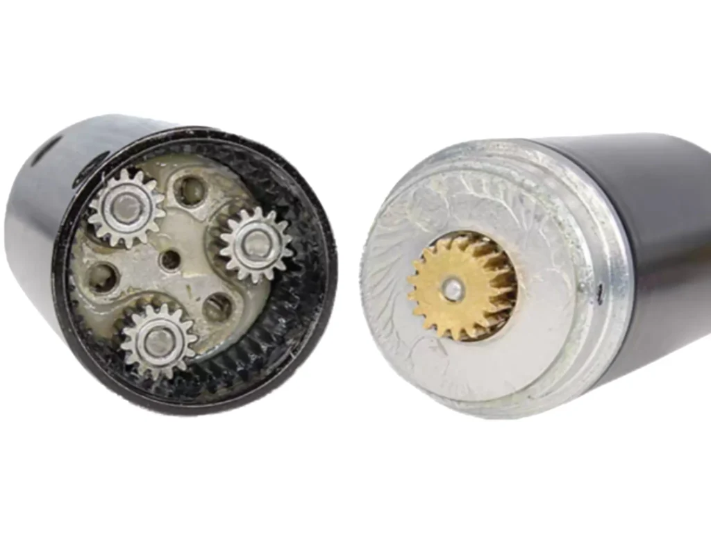
The number of planet gears therefore does not directly determine the reduction ratio, and adding more planets does not guarantee a proportional increase in allowable torque. The complete gearbox design and its verified mechanical torque rating remain the deciding limits.
How Does a Planetary Gear Motor Work?
In the common reduction arrangement, the motor drives the sun gear while the ring gear is fixed to the gearbox housing. The sun gear causes each planet gear to rotate around its own axis while also orbiting around the center of the gearbox.
The planet gears are mounted on the planet carrier. As they move around the fixed ring gear, they drive the carrier at a lower speed than the sun gear. The carrier then transfers this reduced-speed rotation to the output shaft.
The operating sequence can be summarized in three steps:
- Input: The motor shaft drives the central sun gear at relatively high speed.
- Transmission: The sun gear drives the planet gears, which rotate and orbit inside the fixed ring gear.
- Output: The planet carrier rotates at a lower speed and transfers torque to the output shaft.
For this common configuration—ring gear fixed, sun gear input and carrier output—the theoretical single-stage reduction ratio is:
i = 1 + Zr / Zs
Where:
- i is the reduction ratio;
- Zr is the number of teeth on the ring gear;
- Zs is the number of teeth on the sun gear.
The corresponding ideal output speed is:
Output speed = Motor speed / i
This relationship is also demonstrated in MIT OpenCourseWare’s planetary gear train example.
The planet gear tooth count does not appear directly in this ratio formula, but it still affects whether the gears fit together, maintain the correct center distance and can be assembled with evenly spaced planets. The formula must therefore not be used as the only gearbox design check.
In a real gearbox, output torque is not simply the motor torque multiplied by the theoretical ratio. A first estimate is:
Estimated output torque = Motor torque × Reduction ratio × Gearbox efficiency
The result must still remain within the gearbox’s continuous or intermittent mechanical torque rating. For a practical example showing why the ratio alone does not determine final performance, see the 28 mm planetary gearbox 27:1 case study.
Multi-Stage Planetary Reduction
A single planetary stage cannot provide every required reduction ratio. When a lower output speed or a higher overall ratio is needed, two or more planetary stages can be connected in series. The carrier of one stage drives the sun gear of the following stage.
The total reduction ratio is calculated by multiplying the ratio of each stage:
Total ratio = i₁ × i₂ × i₃ × …
For example:
- Two 4:1 stages produce a total ratio of 16:1.
- Three 4:1 stages produce a total ratio of 64:1.
Adding stages allows the gearbox to achieve a higher ratio without increasing its outer diameter significantly. However, it increases gearbox length, the number of moving components and the total mechanical loss.
The overall efficiency is also the product of the efficiency of each stage:
Total efficiency = η₁ × η₂ × η₃ × …
If each stage has an efficiency of 90%, the estimated total efficiency would be:
- One stage: 90%
- Two stages: 81%
- Three stages: 72.9%
These values are only an illustration. Actual efficiency changes with load, speed, lubrication, gear accuracy, material and temperature.
Higher reduction does not automatically mean proportionally higher usable output torque. The theoretical torque multiplication must be corrected for total efficiency, and the calculated result must remain within the gearbox’s continuous and intermittent torque ratings.
Stage position also affects the loading condition. The first stage operates at the highest speed and experiences the greatest number of mesh cycles, while the final stage carries the highest transmitted torque. Gear material, tooth geometry, bearing support and lubrication may therefore differ between stages.
For more detail on how size, material and stage count affect a miniature gearbox, see our micro planetary gearbox materials and selection guide.
What Determines Planetary Gearbox Efficiency?
Planetary gearboxes are often described as efficient, but their gears do not operate through pure rolling contact. During gear meshing, the tooth surfaces experience a combination of rolling and sliding. Sliding is lowest near the pitch point and increases at other positions along the tooth contact path.
Mechanical power is also lost through:
- friction between meshing gear teeth;
- planet pins, bushings or bearings;
- input and output shaft bearings;
- seals and contact surfaces;
- grease churning and lubricant resistance;
- gear misalignment and uneven load sharing.
Gearbox efficiency is defined as:
Gearbox efficiency = Output mechanical power / Input mechanical power × 100%
Efficiency is not one fixed value for every planetary gearbox or every operating point. It changes with the number of stages, transmitted load, input speed, lubricant viscosity, temperature, gear accuracy, bearing design and running condition.
Published efficiency values are normally maximum or nominal values measured under specified conditions. At very light load, fixed friction losses can represent a larger percentage of the transmitted power, so actual efficiency may be lower than the headline value.
A peer-reviewed study on gear-mesh efficiency and sliding friction explains that gear power losses can include sliding friction, rolling friction, lubricant churning and windage. This is why efficiency should be taken from a gearbox datasheet or measured at the intended operating point rather than assumed from the words “planetary gearbox.”
Planetary and worm gearboxes should also not be compared using one universal efficiency number. Their actual performance depends on ratio, geometry, lubrication, load and speed.
Types of Planetary Gear Motors
Planetary gear motors can be classified in several ways, but motor technology, rotor construction, control method and gearbox material should not be treated as one classification system.
For example, a coreless motor may use brushed or brushless commutation, while a servo system may use a brushless motor, brushed motor or stepper motor with feedback. Engineers should therefore define each part of the drive system separately.
Classification by Motor and Control Type
| Motor or control type | Main characteristics | Main limitations | Typical reason to consider it |
|---|---|---|---|
| Brushed DC motor | Simple voltage control, relatively low system cost and high starting torque | Brush wear, electrical noise and limited service life under demanding duty | Cost-sensitive systems with simple speed or direction control |
| Brushless DC motor | Electronic commutation, no brush wear and suitable for continuous operation | Requires a controller and may increase system cost and integration complexity | Long-life, efficient or continuously operating equipment |
| Coreless motor | Low rotor inertia, fast response and smooth acceleration; available in brushed and brushless designs | Winding temperature and peak current require careful control | Compact devices requiring rapid response or smooth low-inertia motion |
| Stepper motor | Discrete position control and useful holding torque at low speed | Can generate heat at standstill and may lose steps in open-loop operation | Low-speed positioning systems with predictable motion sequences |
| Closed-loop servo system | Uses feedback to control position, speed or torque | Requires an encoder, controller and system tuning | Dynamic positioning or applications that must detect position errors |
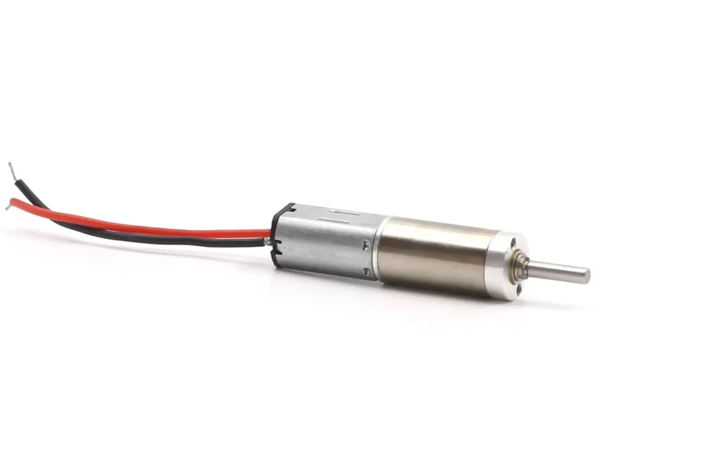
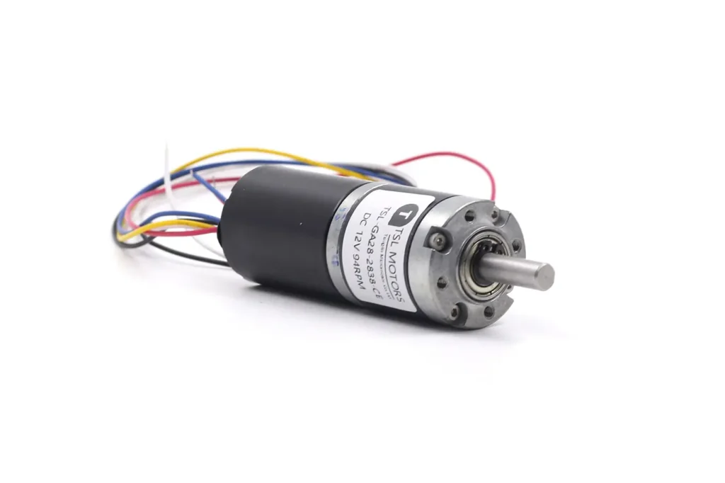
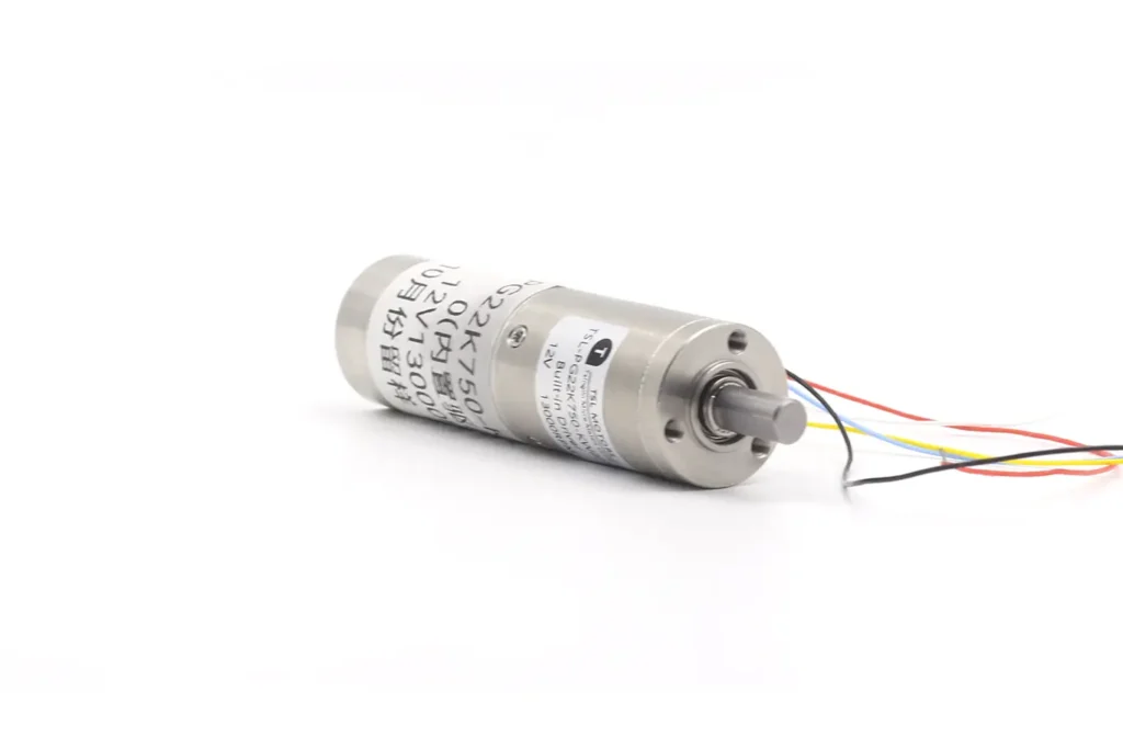
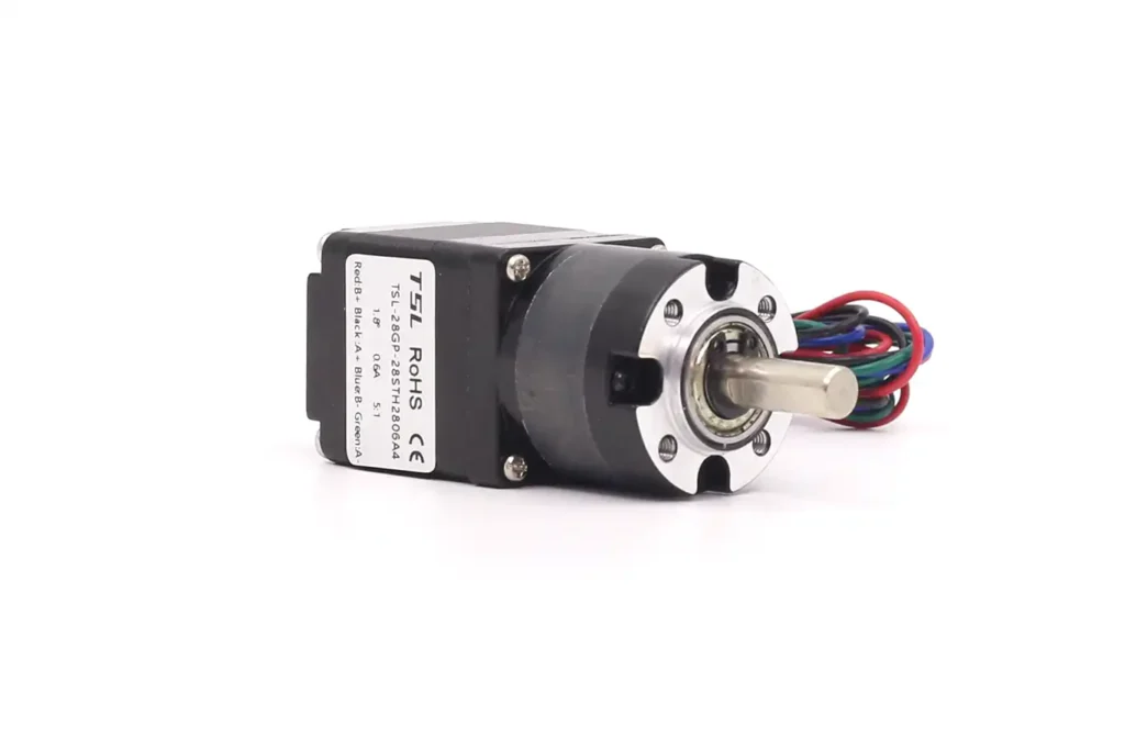
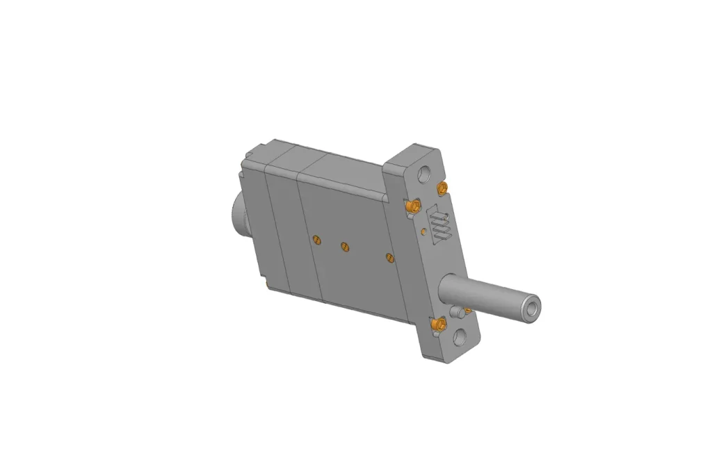
A brushless planetary gear motor requires more than selecting a BLDC motor and a ratio. Output torque, loaded speed, voltage, duty cycle, backlash, driver and temperature must be checked together. These parameters are covered in our brushless planetary gear motor selection guide.
For applications requiring an especially small brushless drive, integrated encoder, driver or customized wiring, see our micro brushless planetary geared motor customization guide.
Classification by Gearbox Construction
| Gearbox construction | Main characteristics | Main limitations | Typical use |
|---|---|---|---|
| Plastic gear set | Lightweight, relatively quiet and economical | Allowable torque, temperature and wear resistance depend strongly on the plastic grade and design | Light-load consumer products and compact battery-powered devices |
| Metal gear set | Higher mechanical strength and temperature resistance are possible | May increase weight, noise and manufacturing cost | Higher-load, shock-loaded or longer-life applications |
| Hybrid construction | Combines plastic and metal components according to the loading of each stage | Requires careful material matching and validation | Applications balancing noise, torque capability, life and cost |
A hybrid gearbox does not always mean “plastic first stage and metal final stage.” The material arrangement should follow the speed, torque, temperature, noise and life requirements of each stage.
These categories describe available design directions, not guaranteed performance levels. Final capability must be confirmed through the specific gearbox drawing, datasheet and application test.
Different Types Planetary Gear Motor Comparison Table
| Classification | Type | Torque Capacity | Noise | Cost | Lifetime | Precision |
| Classification by motor type | Brushed DC Planetary Gear Motor | ⭐⭐ Medium | ⭐⭐ Medium | ⭐ Low | ⭐⭐ Medium | ⭐⭐ Medium |
| BLDC Planetary Gear Motor | ⭐⭐ Medium–High | ⭐⭐ Medium | ⭐⭐ Medium–High | ⭐⭐⭐ Very Long | ⭐⭐⭐ High | |
| Coreless Planetary Gear Motor | ⭐ Medium | ⭐⭐⭐ Very Low | ⭐⭐ Medium | ⭐⭐ Medium | ⭐⭐⭐ High | |
| Stepper Planetary Gear Motor | ⭐⭐ Medium | ⭐⭐⭐ Low | ⭐⭐ Medium | ⭐⭐ Medium | ⭐⭐⭐⭐ Very High | |
| Servo Planetary Gear Motor | ⭐⭐⭐ High | ⭐⭐ Medium | ⭐⭐⭐ High | ⭐⭐⭐ Long | ⭐⭐⭐⭐ Very High | |
| Classification by gearbox type | Plastic Planetary Gearbox Motor | ⭐ Low | ⭐⭐⭐ Very Low | ⭐ Very Low | ⭐⭐ Medium | ⭐ Medium |
| Metal Planetary Gearbox Motor | ⭐⭐⭐ High | ⭐⭐ Medium | ⭐⭐ Medium | ⭐⭐⭐ High | ⭐⭐ Medium | |
| Hybrid Planetary Gearbox Motor | ⭐⭐⭐ High | ⭐⭐ Low | ⭐⭐ Medium | ⭐⭐⭐ High | ⭐⭐ Medium |
The Advantages of Planetary Gear Motors
Planetary gear motors offer several structural advantages, but the actual performance depends on gear accuracy, materials, bearings, lubrication and how evenly the planets share the load.
High Torque Density Through Load Sharing
Multiple planet gears can transmit torque simultaneously around the sun gear. When the load is distributed evenly, this arrangement allows a planetary gearbox to carry more torque within a compact diameter than a comparable single-mesh gear stage.
However, adding more planets does not automatically increase usable torque in direct proportion. Uneven tooth contact, carrier deformation, planet-pin tolerances and bearing clearance can cause one planet to carry more load than the others. The allowable torque must therefore be based on the complete gearbox rating rather than the number of planet gears alone.
Compact Coaxial Layout
In the common configuration, the motor shaft, sun gear, planet carrier and output shaft share the same central axis. This produces a compact inline assembly and simplifies alignment in applications with limited radial space.
A higher reduction ratio may require additional stages, which increases gearbox length, weight and the number of mechanical interfaces. External radial or axial loads may also require a reinforced output bearing or separate load support.
For applications requiring a special output shaft, mounting interface, ratio or bearing arrangement, see our custom planetary gearbox solutions.
Potential for High Efficiency
A well-designed planetary stage can achieve high mechanical efficiency because torque is divided across several gear meshes and the layout does not rely on the heavy sliding contact found in some other reducer types.
Efficiency is not a fixed property of the planetary arrangement, however. It changes with the number of stages, transmitted load, gear accuracy, bearing and seal losses, lubricant viscosity, speed and temperature. Gearbox performance should be evaluated at the intended operating point rather than from a maximum efficiency value alone.
Backlash and Torsional Stiffness Can Be Controlled
Planetary gearboxes can be manufactured for low backlash and high torsional stiffness, which is useful where positioning accuracy and direction reversal matter.
These characteristics are not automatic. Backlash depends on tooth clearance, manufacturing accuracy, bearing play, carrier rigidity, assembly method and wear. Reducing clearance may also increase friction, cost and sensitivity to temperature or contamination. Backlash should therefore be specified and measured under defined load and test conditions.
Load Capacity and Service Life Depend on the Complete Design
The distributed gear arrangement can provide good load capacity and resistance to moderate operating disturbances. Nevertheless, the gearbox should not be described as inherently shock-proof.
Sudden stops, impacts, rapid reversals and high reflected load inertia can overload the gear teeth, planet pins, carrier or bearings. Continuous torque, intermittent torque and peak torque must be treated as separate limits. Reliable service life depends on staying within these limits while maintaining suitable lubrication, alignment and operating temperature.
Comparative Analysis: Planetary vs. Worm vs. Spur Gears
While the planetary gear motor is often the superior choice for high-performance applications, the market offers distinct alternatives. A nuanced selection process requires understanding the specific trade-offs of Spur Gear Motors and Worm Gear Motors.
The Spur Gear Motor: Simplicity and Cost-Effectiveness
The spur gear motor represents the simplest form of gearing, consisting of straight-toothed gears mounted on parallel shafts.
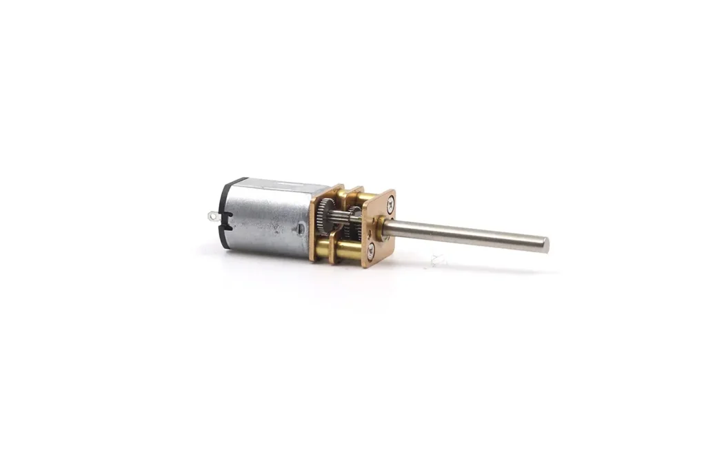

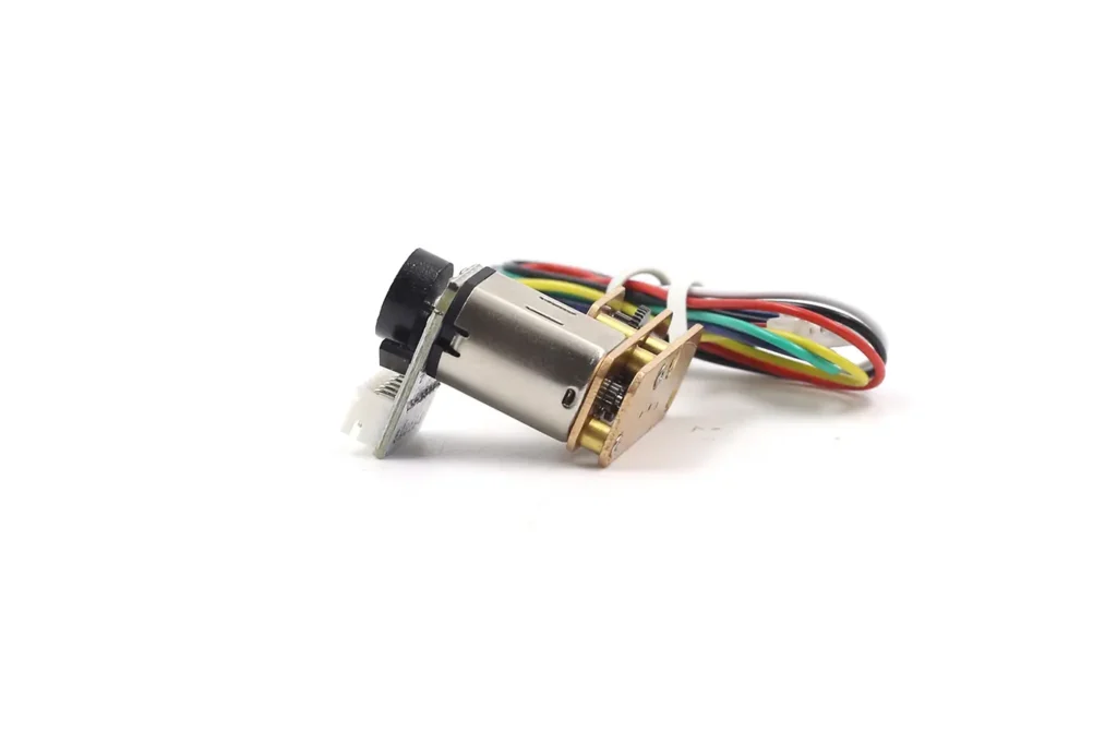
- Architecture: The drive train is a cascade of gear pairs (pinion driving gear).
- Performance: Torque is transferred through a single line of contact. This limits load capacity and makes the teeth susceptible to shock loading.
- Acoustics: The sudden engagement of the full tooth width creates impact noise, making spur gears louder, especially at high speeds.
- Primary Advantage: Low manufacturing cost and ease of maintenance. For non-critical, low-torque applications like simple toy actuation or basic vending machines, spur gears provide a functional, economical solution.
The Worm Gear Motor: The Self-Locking Specialist
Distinct from the coaxial planetary design, the worm gear motor employs a screw-and-wheel configuration.
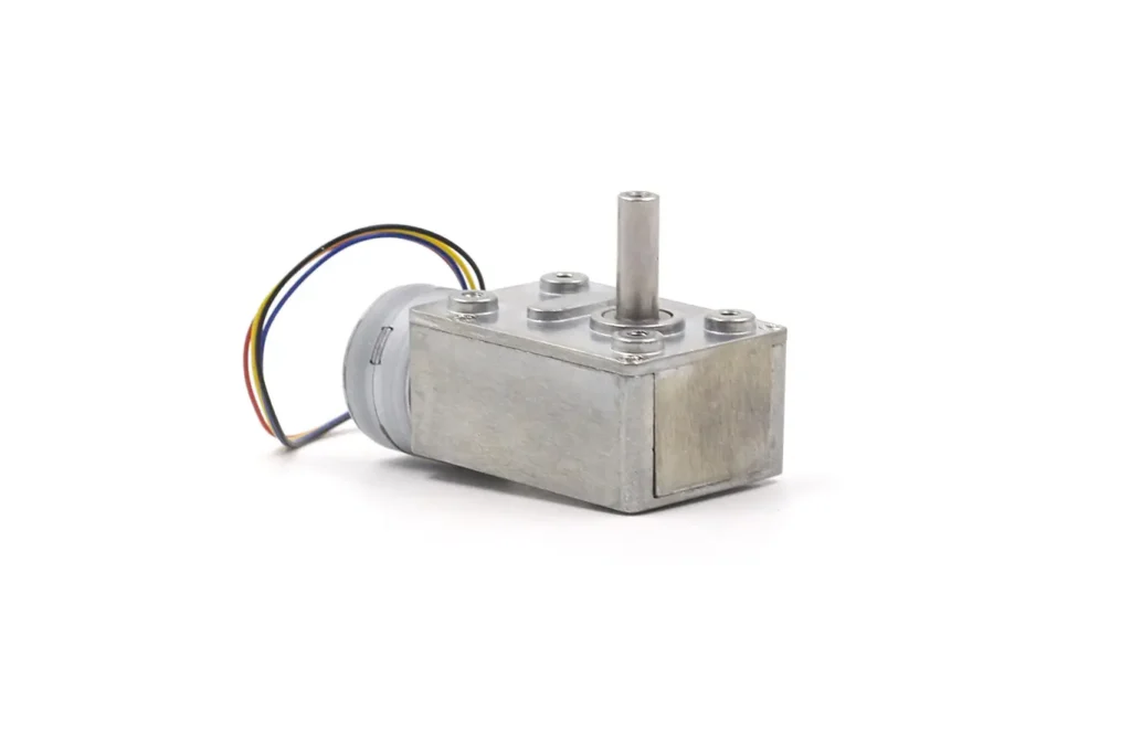
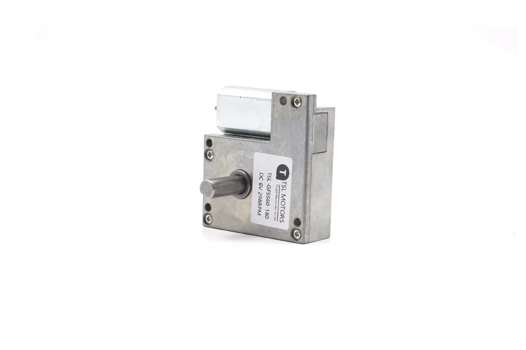
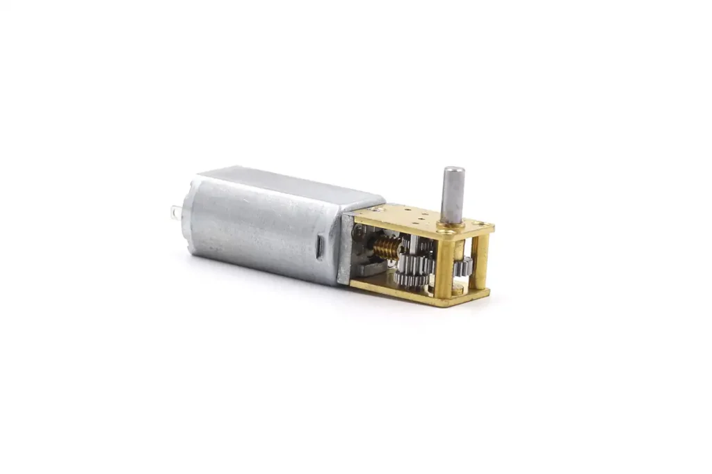
- Architecture: The input shaft drives a spiral worm (screw), which meshes with a worm wheel. This creates a 90-degree right-angle output.
- Self-Locking Mechanism: A unique feature is its ability to be self-locking. Due to the friction angles, the wheel generally cannot drive the worm. This provides a passive braking effect, ensuring that a lifted load does not drift downward when power is cut—a critical safety feature in hoists and elevators.
- Efficiency Penalty: The reliance on sliding contact results in low efficiency (30-60%). High ratios lead to significant energy loss as heat.
- Wear and Backlash: The sliding action wears the softer bronze wheel, leading to increased backlash over time, making them less suitable for precision positioning.
Detailed Technical Comparison Table
The following table synthesizes the operational characteristics, providing a decision framework for engineers.
| Feature | Planetary Gear Motor | Worm Gear Motor | Spur Gear Motor |
| Transmission Geometry | Coaxial (In-Line) | Right Angle (90°) | Parallel Shaft (Offset) |
| Torque Density | High (Load shared by 3+ planets) | Medium | Low (Single contact point) |
| Efficiency | High (90% - 98% per stage) | Low (30% - 60%) | Medium-High (85% - 90%) |
| Backlash (Precision) | Low (< 5 arcmin available) | High | Medium |
| Noise Level | Low (Balanced forces) | Low (at low speeds) | High (Tooth impact) |
| Backdrivability | High (allows compliance) | Zero (Self-locking) | High |
| Heat Generation | Low | High (Sliding friction) | Moderate |
| Cost | Moderate to High | Moderate | Low |
| Typical Application | Robotics, Medical, Smart Locks | Hoists, Conveyors, Lifts | Toys, Simple Automation |
Insight: The “Hybrid” Approach
Recent trends in robotic dexterity have led to hybrid designs. For example, anthropomorphic robotic hands may utilize a worm gear stage for the proximal joints (to provide self-locking holding capability without power) coupled with a planetary gear stage for the distal joints (to provide speed and efficiency).
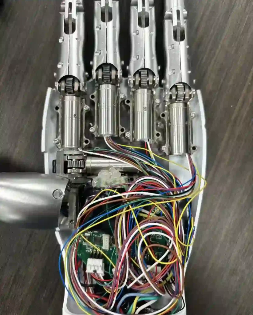
This highlights that while planetary motors are generally superior, the specific physics of the application (e.g., the need for passive holding torque) may dictate a mixed approach.
Planetary Gear Motor Applications
Sector Analysis I: Advanced Robotics and Industrial Automation
Robotics is one of the strongest drivers behind innovations in high-torque, low-backlash actuation technologies. The shift from rigid industrial robots to collaborative and dexterous systems places planetary gear motors at the center of robotic design.
Collaborative Robots (Cobots) & Backdrivability
Unlike traditional fenced robots, collaborative robots work directly alongside humans. This interaction requires a safety property known as compliance or backdrivability—the ability for the robot arm to yield when pushed by an external force (e.g., a collision with a person).
While larger joints tend to use higher-power actuators, micro planetary gear motors are ideal for end-effectors (electric grippers, tool modules) and precision wrist joints. They are essential for achieving dexterous motion and fine control.

Backdrivability challenge:
High reduction gearboxes typically have high friction and resist backdriving. Worm gears are inherently non-backdrivable.
Planetary advantage:
Because of their high efficiency and rolling contact, planetary gear motors provide excellent backdrivability.
This allows the motor controller to detect external torque peaks (via current feedback) and actively reverse or stop motion to prevent injury. Their low inertia design minimizes the reflected inertia defined as:J_ref = J_load / N²,making the robot feel lighter and safer during human interaction.
Dexterous Manipulation: A Micro Planetary Revolution
Replicating human hand function requires actuators small enough to fit inside the geometry of finger phalanges.
Miniaturization:
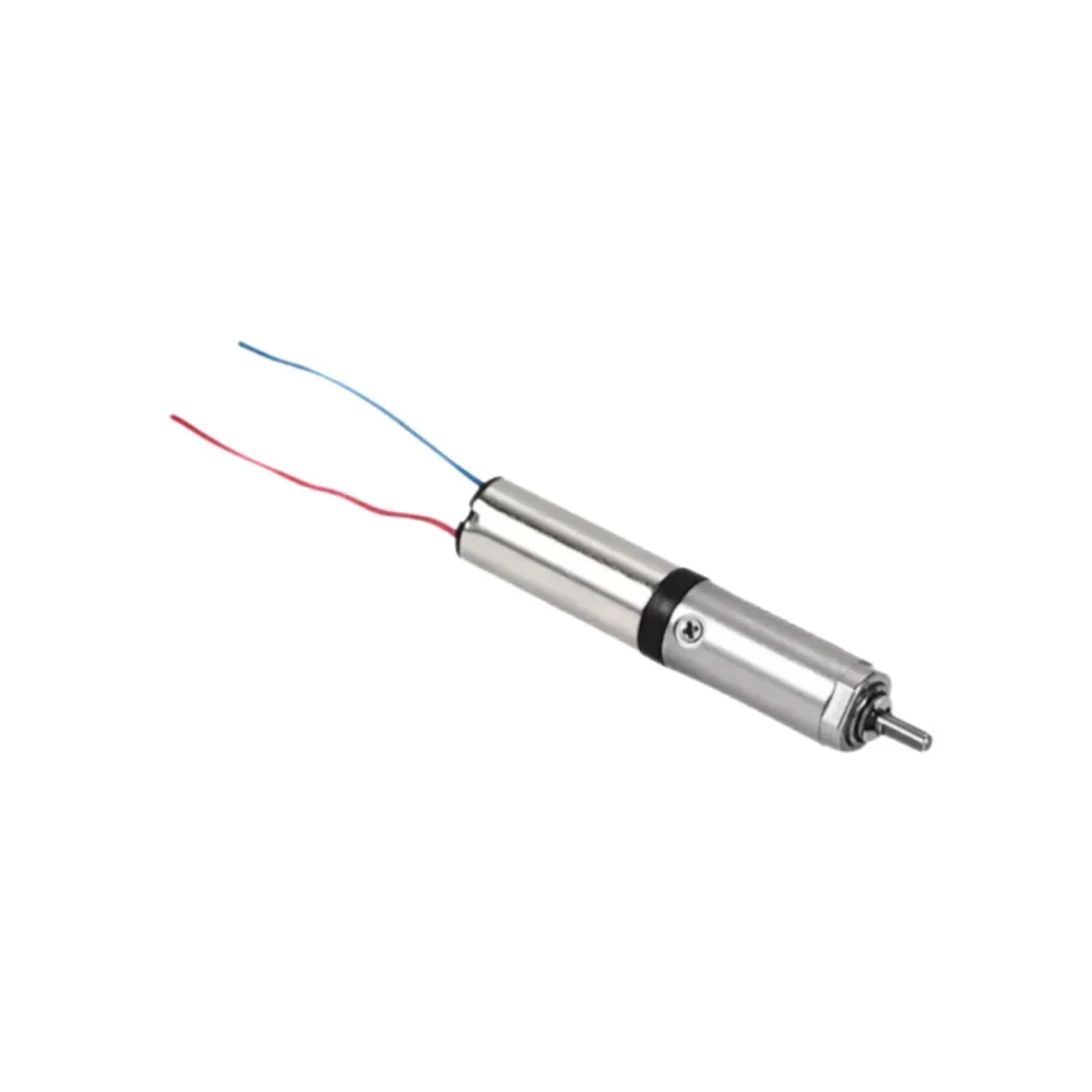
Our smallest planetary gear motors are as small as 6 mm in diameter.
Application:
In robotic hands, a 6 mm planetary gearbox paired with a coreless or brushless motor provides gripping force. The coaxial structure allows the actuator to be embedded directly inside the finger linkage.
Torque requirement:
A typical robotic finger joint may require 1–3 Nm of torque. Multi-stage micro planetary gearboxes convert the high speed of a 6 mm motor (e.g., 20,000 RPM) into the low-speed, high-torque output needed for grasping. Compact multi-stage configurations can achieve 100:1 or higher ratios within <30 mm total length.
Electric Grippers vs. Pneumatics
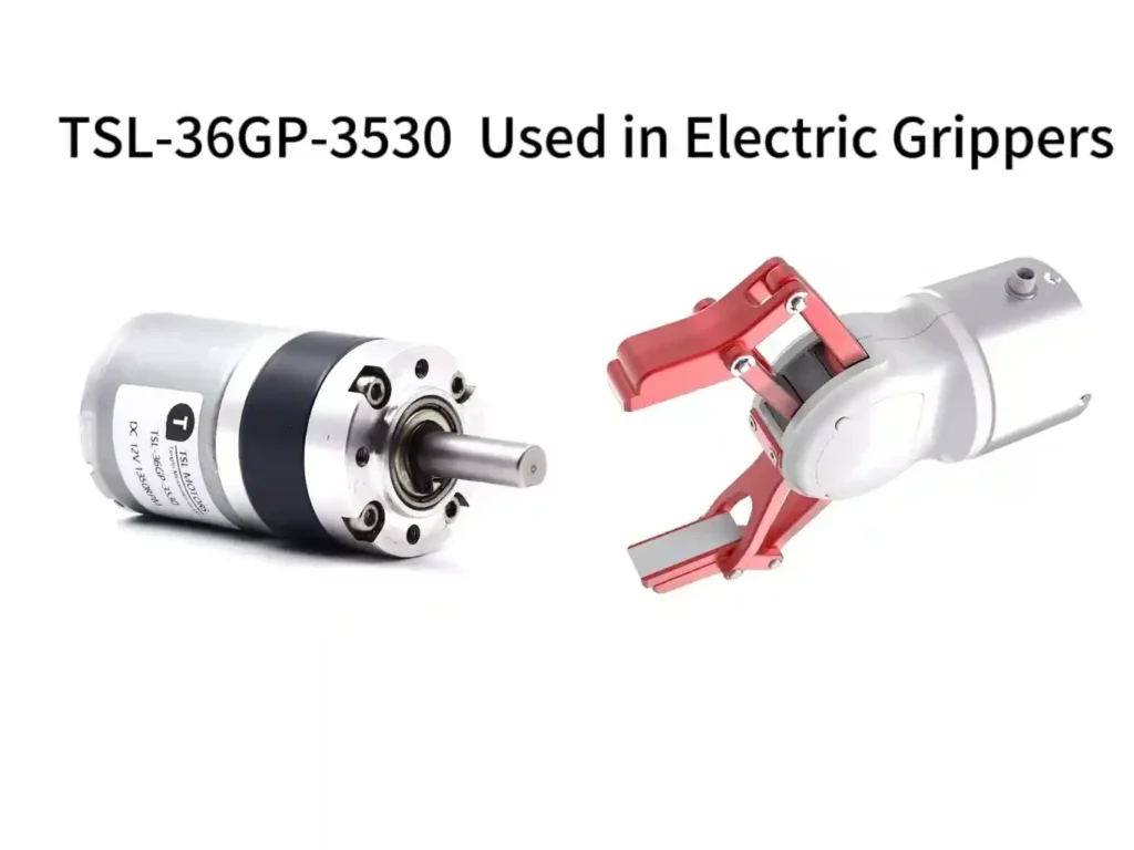
Industrial automation is rapidly shifting from pneumatic grippers (noisy, inefficient, poor force control) toward electric grippers.
Precision control:
Electric grippers driven by planetary gear motors enable precise control of gripping force (via current) and position (via encoder). With only software adjustment, the same gripper can handle fragile eggs or heavy steel components.
Self-locking in grippers:
Some electric grippers integrate high-ratio planetary gearboxes or specially designed lead screws to hold force during power loss—achieving worm-gear-like safety while maintaining higher efficiency.
Sector Analysis II: Medical Technology and Surgical Precision
Medical applications demand the perfect blend of reliability, sterility, and low noise. These systems are often life-critical, placing extremely rigorous performance requirements on motors.
Powered Surgical Staplers: The High-Torque Challenge
Modern surgery increasingly relies on powered staplers that cut and seal tissue simultaneously.
The Physics of Stapling:
Driving titanium staples through varying tissue densities requires a massive, instantaneous burst of torque—often up to 30 Newton-centimeters (N.cm).

The Planetary Solution:
Handheld staplers must be lightweight to prevent surgeon fatigue. A 16mm or 22mm planetary gear motor is the standard solution. It can deliver the required peak torque from a compact battery-powered unit. The high efficiency ensures the battery lasts through lengthy procedures.
Sterilization:
These motors must often withstand autoclave cycles (steam sterilization at 134°C). Manufacturers use specialized high-temperature windings, magnets, and lubricants, along with sealed planetary gearheads, to survive repeated sterilization without degrading performance.
Insulin Pumps and Control Theory
Portable insulin pumps deliver precise micro-doses continuously, 24/7.
Control challenge:
The motor must overcome static friction to dispense tiny amounts of insulin and then stop instantly. Traditional PID controllers struggle with nonlinear friction behavior at extremely low speeds in miniature geartrains.
Advanced control (LQG):
Research shows that Linear Quadratic Gaussian (LQG) control with a Kalman filter performs better for insulin pump motors. It estimates motor states more accurately, compensates gearbox noise and friction, reduces rise/settling time, and ensures precise drug delivery.
Acoustics & patient anxiety:
Noise affects user comfort. Loud pumps can cause anxiety or disturb sleep. Planetary gearboxes offer smoother acoustic characteristics than spur gears.
Noise levels must typically remain below 30–40 dBA. We often use hybrid gear trains—plastic in early stages (for low noise) and metal in final stages (for torque strength).
Laboratory Automation
In automated blood analyzers, HTS systems, and DNA sequencers, throughput determines economic viability. High-speed planetary motors drive pipetting gantries and robotic samplers through thousands of rapid accelerations and positioning cycles.
Speed & durability
High-speed operation demands excellent efficiency and thermal performance. Planetary gearbox efficiency keeps temperature rise low—critical inside sealed analyzer enclosures. Multi-point load sharing ensures durability during 24/7 operation.
Precision barrier: Eliminating repeatability errors
This is a zero-tolerance domain.
Risk amplification:
Even sub-millimeter positioning errors can cause pipette tips to strike tube walls at high speed, resulting in splashing, sample loss, or cross-contamination that ruins entire batches.
Planetary solution:
Planetary gear motors offer low backlash and excellent repeatability. Their rigid structure and precise machining minimize settling time and ensure accurate homing—critical for accuracy and throughput.
We commonly supply customized 12 mm to 22 mm actuators optimized for smoothness to prevent bubbles or overflow during high-speed liquid handling. For these applications, low backlash is not optional—it is a mandatory safety requirement.
Sector Analysis III: The Invisible Home – Smart Automation
The “smart home” movement is built on the idea of invisible actuation, where intelligence is embedded seamlessly into everyday objects.
Smart Door Locks & Teardown Insights
Modern smart locks (August, Yale, Schlage) must fit existing door hardware.

Torque requirement:
Door locks often require 1.5–2.0 Nm of torque to turn the latch, especially when misalignment or weathered seals increase friction.
Teardown observations:
Inside mainstream smart locks, 10–16 mm full-metal planetary gear motors are ubiquitous. The coaxial shape allows them to fit inside round lock bodies or knobs.
Mechanism:
The motor drives the planetary gearbox, which turns the output shaft connected to the latch tailpiece. Sensors monitor position, and if jamming is detected via current spike, the motor reverses to avoid damage.
Curtain & Shade Tubular Motors
Automatic blinds rely on tubular motors housed inside roller tubes.
Geometry is destiny:
Planetary gearboxes have a cylindrical, coaxial form factor, making tube-integration feasible. Worm gears protrude too much to fit into the tube.
Internal structure:
These motors use long, multi-stage gearboxes (3–4 stages) to achieve high ratios (e.g., 64:1 or higher) required to lift heavy blackout curtains.
DIY & solar-powered shades:
High gearbox efficiency (up to 95%) enables solar-powered cordless blinds. A small solar panel can fully support daily up/down cycles due to the motor’s low energy consumption.
Sector Analysis IV: Automotive Mobility and ISO Standards
As vehicles shift toward software-defined architectures, mechanical linkages are being replaced by precise by-wire electromechanical actuators.
Electronic Parking Brake (EPB)
Mechanical handbrakes are obsolete.
Application:
EPB systems mount a motor directly on the brake caliper. Pressing a button activates the motor and leadscrew to clamp the brake pads.
Planetary requirement:
The system needs high torque to secure the vehicle on slopes. Planetary gears amplify torque from compact 12V DC motors. High efficiency ensures fast braking response in milliseconds.
LiDAR & Sensor Cleaning
Autonomous vehicles rely on LiDAR sensors spinning at constant, precise speeds.
Stability:
Planetary motors provide the smooth, low-vibration rotation required. Any gearbox jitter appears in the LiDAR point cloud as noise or blurring.
Cleaning actuators:
Retractable nozzles for cleaning cameras and sensors also use small planetary actuators for extension/retraction under harsh conditions.
Automotive Noise Standards
Automotive applications follow strict acoustic regulations.
ISO 16750:
Defines environmental testing for vehicle electrical equipment, including sinusoidal and random vibration—to ensure gearboxes survive harsh road conditions.
ISO 10844:
Specifies standardized road surfaces for vehicle pass-by noise measurements. For EVs, actuator noise becomes more significant. Planetary gears are quieter than spur gears, helping manufacturers meet low-noise requirements.
Engineering-Based Selection
Selecting the correct planetary gear motor is a multidimensional optimization problem. It requires physics-based modeling—not just choosing a voltage.
Torque Calculation & Motion Physics
Proper motor selection begins with calculating the required torque. For mobile robots, torque depends on friction and acceleration.
Friction load:
F_friction = μ × N
where μ is the friction coefficient (e.g., 0.7 for carpet) and N is the normal force (weight).
Acceleration load:
F_acceleration = m × a
where m is mass and a is the desired acceleration.
Total required torque (T):
T = (F_friction + F_acceleration) × r_wheel
where r_wheel is the wheel radius.
Example
A 20 kg robot, on carpet (μ = 0.7), accelerates at 0.2 m/s² with a wheel diameter of 10 cm (r = 0.05 m).
F_f = 0.7 × 20 kg × 9.8 m/s² = 137.2 N
F_a = 20 kg × 0.2 m/s² = 4 N
Total force = 141.2 N
Torque = 141.2 N × 0.05 m = 7.06 Nm
Selection conclusion:
This application likely requires a high-speed DC motor paired with a high-ratio planetary gearbox (e.g., 50:1).
Load Curves: Continuous vs. Peak
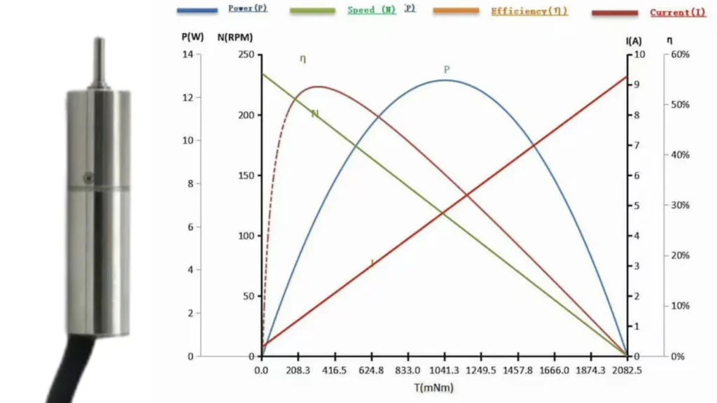
Engineers must distinguish between:
Continuous torque:
The torque a motor can deliver indefinitely without exceeding thermal limits. Planetary gearboxes perform well here due to load sharing among multiple teeth.
Peak / stall torque:
The maximum torque needed to start moving the load. Planetary gearboxes can typically withstand 2–3× the rated torque during brief impact events because of their robust multi-tooth engagement.
Inertia Matching
n high-dynamic applications such as robotics, the motor rotor inertia (J_m) should be matched to the reflected load inertia (J_reflected).
Reflected inertia:
The gearbox reduces the apparent load inertia by the square of the reduction ratio N.
J_reflected = J_load / N²
Optimization:
Planetary gearboxes allow high reduction ratios, significantly lowering reflected inertia, improving controllability, and enhancing dynamic response.
Manufacturing, Quality, and Global Standards
In a globalized supply chain, the origin and process of gearbox manufacturing influence reliability just as much as the design itself. The manufacturing method determines the “grade” of the gear.
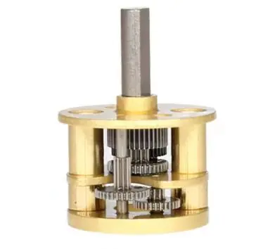
Manufacturing Processes: Skiving vs. Hobbing vs. Powder Metallurgy
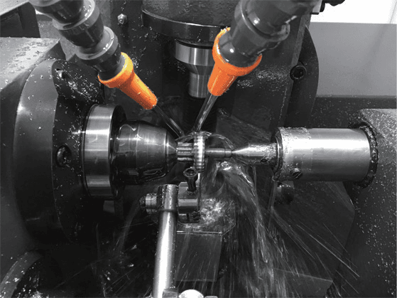
Power Skiving
A modern machining method suitable for 5-axis CNC machines. It can rapidly and precisely produce internal ring gears, which are critical components of planetary systems. Skiving is faster than shaping and more precise than broaching, enabling high-quality planetary gear rings to be mass-produced.
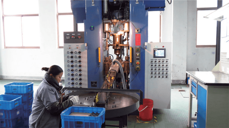
Powder Metallurgy (Sintering)
Metal powder is pressed into a mold and then sintered at high temperature. This allows low-cost production of geometrically complex gears. Widely used in automotive and consumer-grade planetary gearboxes. Cost-effective, but impact strength is lower than machined steel gears.
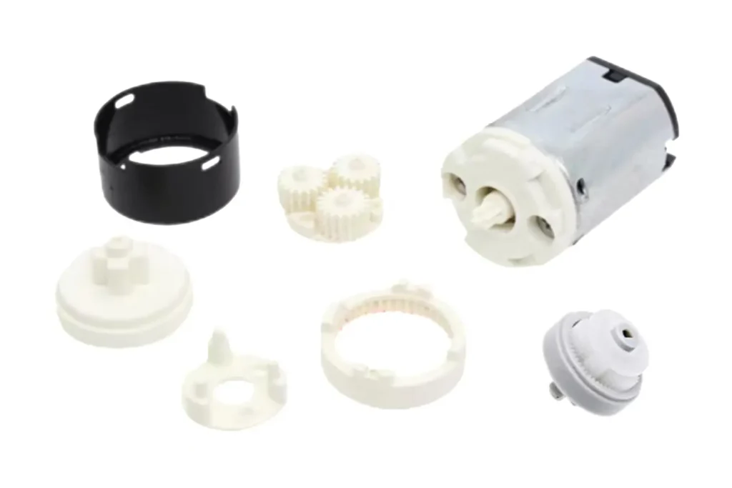
Injection Molding
Plastic gears (POM/nylon) are used where low noise and low cost are priorities. In medical planetary gearboxes, the first stage is often plastic for quiet operation, while later stages use sintered or machined steel for torque handling.
Quality Standards: AGMA and ISO
Gear quality is not subjective—it’s defined by engineering standards.
AGMA (American Gear Manufacturers Association)
AGMA standards (e.g., AGMA 2001, AGMA 2015) classify gears by precision. High-precision aerospace gears may reach AGMA Class 12, while commercial gears are typically Class 8.
ISO 1328
The international equivalent. In ISO standards, a lower number indicates higher precision (the opposite of older AGMA scales). High-performance planetary gears for robotics typically reach ISO Class 6 or 7.
Meaning:
ISO Class 6 gears have tighter tolerances in tooth profile and pitch error, resulting in lower transmission error, less vibration, and significantly reduced noise.
coustic Testing Methodology
To meet medical and automotive requirements, TSL MOTOR perform strict noise testing.
Setup:
Tests are conducted inside an anechoic chamber to eliminate background noise.
Procedure:
Microphones are placed at a fixed distance (e.g., 10 cm or 1 m). The motor runs at various speeds and loads.
Analysis:
Engineers look for frequency peaks that indicate gear meshing issues such as eccentricity or damage. Overall sound pressure level (dBA) is measured. High-quality planetary motors intended for medical devices often need to stay below 45 dBA.
Conclusion: The Precision Imperative
The planetary gear motor stands as a testament to the elegance of mechanical engineering. By mimicking the orbital dynamics of the cosmos, it achieves a terrestrial feat: packing immense power into a microscopic footprint.
While spur gears remain relevant for cost-sensitive, low-impact applications, and worm gears retain a niche in self-locking vertical lifts, the planetary gear motor is the undisputed driver of the high-tech economy.

From the 6mm motor securing a smart home to the high-torque actuator powering a cobot’s elbow, this technology bridges the gap between digital commands and physical action.
As industries continue to push the boundaries of miniaturization and efficiency—demanding motors that are quieter, stronger, and smarter—the planetary gear motor will remain the beating heart of automation.
For the global engineer, the choice is clear: when performance cannot be compromised, the planetary system is the standard.
FAQ
Q1.What is a planetary gear motor?
A1:A planetary gear motor is a gear system where multiple planet gears rotate around a central sun gear inside a ring gear. This structure provides high torque density, compact size, and excellent efficiency.
Q2:Why are planetary gear motors used in compact or high-load applications?
A2:Because the load is shared across multiple planet gears, the system can deliver high torque within a very small volume. This makes them ideal for medical devices, smart locks, robotics, and precision instruments.
Q3:How do planetary gear motors compare with spur gear motors?
A3:Planetary gears generally offer higher torque, better efficiency, and more uniform load distribution. Spur gear motors are simpler and cheaper but cannot match the compact torque density of a planetary system.
Q4:What materials are commonly used for planetary gearboxes?
A4:
- Plastic gears: quiet, economical, suitable for light loads
- Metal gears: durable, high torque, suitable for demanding applications
- Powder-metal gears: balanced cost and strength
- Cut gears (machined steel/bronze): highest precision and durability
ortfolio.
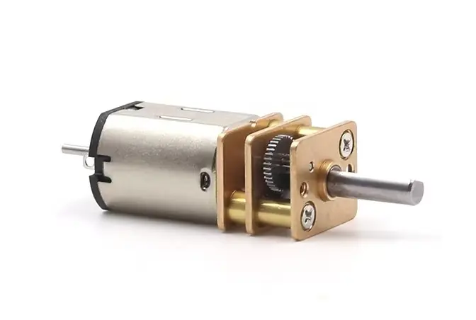
Planetary Gear Motor
A planetary gear motor combines a micro planetary gearbox with a DC motor, serving as a driving device designed to reduce speed and increase torque. These motors are typically cylindrical and made from materials such as steel or brass. In some cases, plastic components are used to meet specific size and power requirements.