Achieving “degree-level” control with coreless motors is not only feasible. It is a baseline requirement for modern high-performance mechatronic systems. Advanced systems already routinely achieve sub-degree and even arc-second precision.
This high precision cannot be achieved by a single component. It requires a “precision ecosystem” where five key elements work together:
- the coreless motor (providing physical potential)
- a high-resolution encoder (providing precise feedback)
- a servo driver (calculating error and issuing commands)
- advanced control algorithms (compensating for disturbances)
- dedicated hardware with optimized drivers (ensuring high-frequency, low-latency control).
This article will shift from the component level to the system level. It will analyze the engineering principles for achieving degree-level control.
TSL Motor has been deeply involved in the DC motor field for over ten years. It is a leading DC motor manufacturer in China.If you are looking for sub-degree, high-precision mechatronic products and solutions, please contact us.
key Takeaways
- Precision Ecosystem: Precision Ecosystem Sub-degree accuracy is the true engineering challenge. This requires a complete mechatronic ecosystem working together.
- Motor Foundation: No Cogging Effect Coreless motors eliminate cogging torque. This ensures the motor runs smoothly at low speeds.
- Key Characteristics: Low Inertia & Linearity The motor’s rotor inertia is extremely low, so dynamic response is fast. Its linear characteristics also simplify the control model.
- Feedback Prerequisite: High-Resolution Encoder The encoder determines the system’s precision limit. High-resolution encoders provide the digital basis for sub-degree control.
- Algorithm Key: Feedforward Control PID control is reactive and always has tracking error. Feedforward control, however, predicts and compensates in advance.
- Smoothness Guarantee: S-Curve & FOC S-Curves prevent vibration by limiting “Jerk”. FOC control eliminates torque ripple to ensure smoothness.
- Core Challenge: Dynamic Tuning & Mechanical Limits Low inertia makes the system hard to tune and prone to oscillation. Mechanical resonance and compliance also limit the final precision.
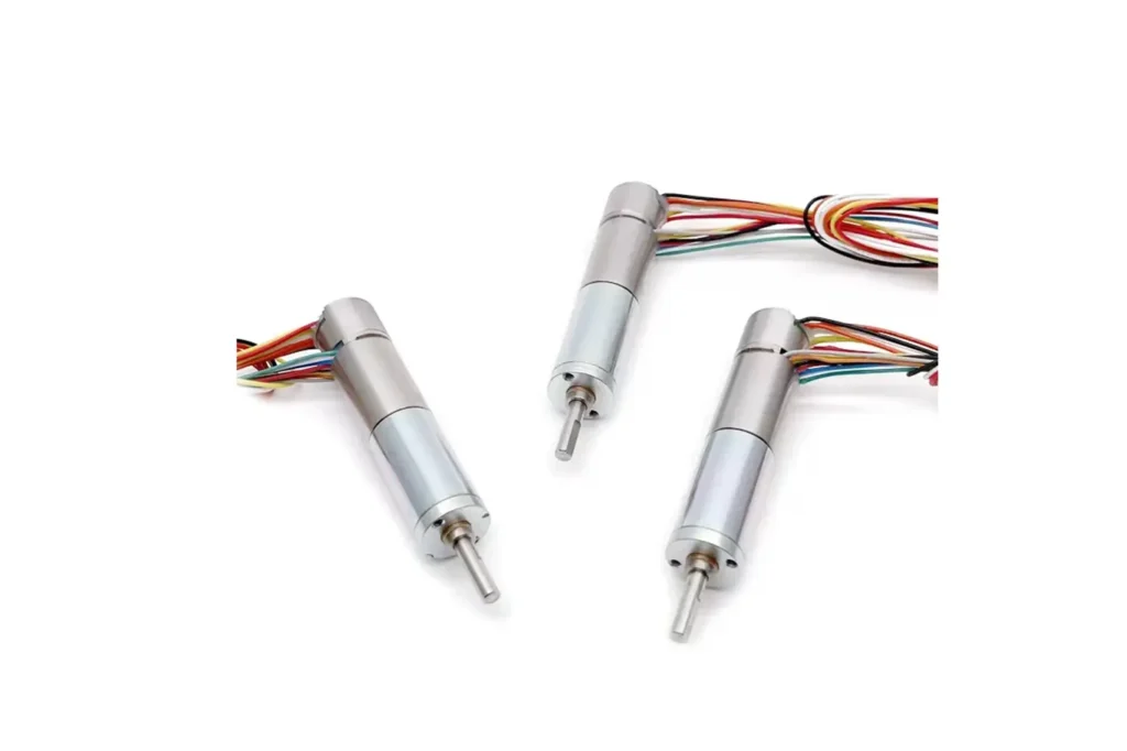
The Ideal Actuator: Coreless Motor
At the heart of high-precision motion control systems lies the drive technology. Coreless DC motors, due to their unique structural design, lay the physical foundation for achieving sub-degree (sub-degree) or even higher angular precision.
Compared to traditional iron-core motors, coreless motors show a decisive advantage in eliminating inherent defects.
Overcoming Cogging and Inertia
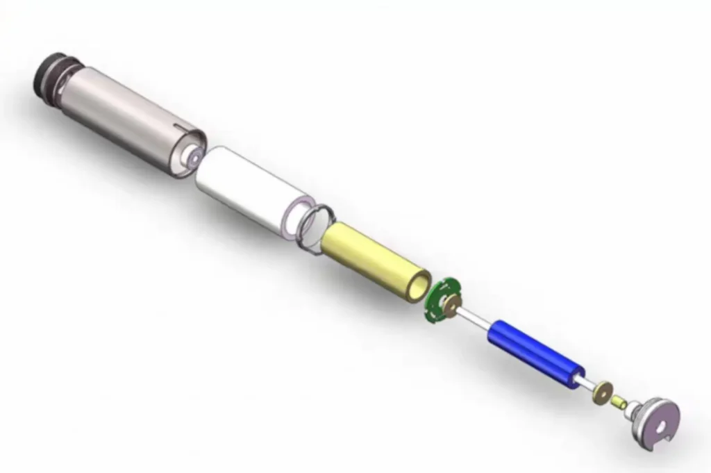
The greatest advantage of the coreless motor design is its elimination of cogging torque. Unlike traditional iron-core motors with laminated steel cores, the rotor of a coreless motor is typically a self-supporting, hollow copper winding. Therefore, there is no magnetic “detent” or reluctance variation caused by the iron core aligning with the stator magnets.

This elimination of cogging torque is a prerequisite for high precision, as it ensures the motor can maintain smooth, even motion even at very low or near-zero speeds, thus avoiding the non-uniformity that iron-core motors struggle with at low speeds.
Furthermore, this design gives coreless motors extremely low rotor inertia. Since the rotor contains only a lightweight copper winding, its mass is minimal, resulting in a very low moment of inertia. This low-inertia characteristic is a key requirement for high-precision servo systems, enabling the motor to have an extremely high dynamic response, rapid acceleration/deceleration, and fast positioning times.
High Efficiency and Thermal Stability
The high efficiency of coreless motors is crucial for maintaining long-term precision. By eliminating the iron core, the coreless design avoids the eddy current and hysteresis losses found in traditional iron-core motors. Their energy conversion efficiency can often exceed 70%, and in some products, even reach over 90%.
The most direct benefit of high efficiency is minimized heat generation. Coreless windings are very sensitive to overheating, as they lack the thermal buffering capacity of an iron core. By minimizing wasted energy (i.e., heat), the system can maintain thermal stability.
In precision motion control, thermal stability is critical because temperature fluctuations can cause changes in resistance and thermal expansion of mechanical parts, both of which directly degrade position accuracy.
Therefore, high-efficiency electronic control, such as Field-Oriented Control (FOC), is actually an important thermal management tool used to maintain the physical integrity of the measurement system, thereby ensuring sustained sub-degree precision.
Linear Control Characteristics
The ironless design not only eliminates cogging but also eliminates iron-related magnetic losses, such as hysteresis and eddy currents.
This results in a highly linear system:
- Torque is strictly proportional to current.
- Speed is strictly proportional to voltage.
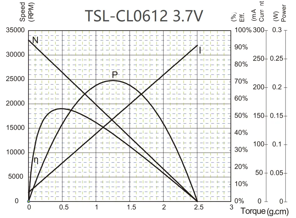
This linearity makes the motor a completely predictable component, greatly simplifying the mathematical modeling for the controller.
For a coreless motor, the control model is simple: “To get X torque, apply Y current.” For an iron-core motor, the model is highly non-linear (e.g., affected by magnetic saturation, hysteresis). This superior linearity is the solid foundation upon which all advanced control algorithms (like PID and feedforward) are built.
BLDC and Dynamic Challenges
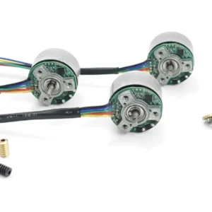
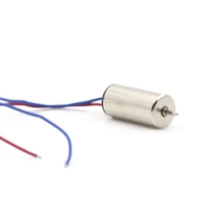
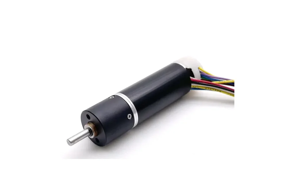
In applications pursuing extreme precision, although coreless brushed motors (often using precious metal brushes to improve low-current performance ) can be used, coreless brushless DC (BLDC) motors are the dominant choice.

BLDC technology replaces mechanical brushes and commutators with electronic commutation, fundamentally eliminating mechanical wear, electrical noise, and lifetime limitations. More importantly, electronic commutation is a prerequisite for implementing advanced vector control algorithms like Field-Oriented Control (FOC).
However, this low-inertia characteristic also presents dynamic stability challenges. A low-inertia system lacks natural damping and reacts very strongly to control inputs and external disturbances. While this is beneficial for fast response, it also makes the system extremely sensitive to control loop gains, easily leading to oscillation and overshoot if not properly tuned.
Therefore, coreless motors are the best components for achieving precision, but also the most difficult systems to tune electronically.
Beyond “Within Degrees”
The user’s demand for control “within degrees” actually sets a low bar for modern servo systems. For today’s precision motion systems, control accuracy has long surpassed whole degrees; the real focus is on sub-degree precision, i.e., 0.1° or even higher, at the arc-minute or arc-second level.
Precision Feasibility
In many simple stepping and repetitive applications, such as stepper motor systems, their nominal step angle is typically 1.8°, making degree-level precision a routine requirement.
However, high-standard industrial, medical, and robotics applications demand much higher precision.
For example, angle sensors in humanoid robots and high-performance automotive applications often require accuracy in the 0.1° to 1° range. Professional surgical robots and complex optical systems demand precision down to the arc-minute (1/60°) or even arc-second level.
The hardware is capable of measuring displacements far smaller than 1°, confirming that the control system for a coreless motor is fully capable of achieving sub-degree tasks at the digital level.
The following table summarizes the relationship between encoder bit depth and theoretical resolution:
Encoder Angular Resolution Benchmarks
| Encoder Type/Bit Depth | Positions per Revolution (N) | Theoretical Resolution (Degrees) |
| Stepper Motor (200 steps) | 200 (Open-loop) | 1.8° (Step angle) |
| 12-bit Absolute Encoder | 4,096 | 0.088° |
| 15-bit Absolute Encoder | 32,768 | 0.011° |
| 18-bit Absolute Encoder | 262,144 | approx 0.00137° |
The System’s Eyes: High-Resolution Encoder
A coreless motor is essentially “blind”; it must rely on a high-resolution sensor (encoder) to achieve any form of position control.
A coreless motor system is inherently a servo system, meaning the final positioning accuracy is not determined by the motor itself, but by the quality of the feedback device and its integration with the control system.

High-precision positioning must rely on absolute encoders, as they can report the exact angle immediately upon power-up, without the homing sequence required by incremental encoders.
When selecting sensor technology, a balance must be struck between resolution and environmental robustness:
- Optical Encoders: Typically offer the highest resolution and accuracy due to their precision-etched discs. However, their main limitation is sensitivity to environmental factors. Dust, oil, electrical noise, shock, and vibration can all interfere with the light path, causing reading errors and degrading accuracy.
- Magnetic Encoders: This type offers better robustness and durability, capable of operating reliably in harsh environments with moisture, dust, or high vibration. While historically having lower resolution, modern technology is closing the gap. However, they can be susceptible to interference from external magnetic fields.
- Inductive Encoders: This technology is seen as a compromise, offering the insensitivity to contamination and vibration of magnetic encoders while providing high accuracy approaching that of optical solutions. Consequently, inductive encoders are widely used in general-purpose automation and medical equipment (like CT scanners).
The System’s Brain: Servo Control
Achieving and maintaining sub-degree precision relies on a complex closed-loop servo control system that must precisely manage current, velocity, and position.
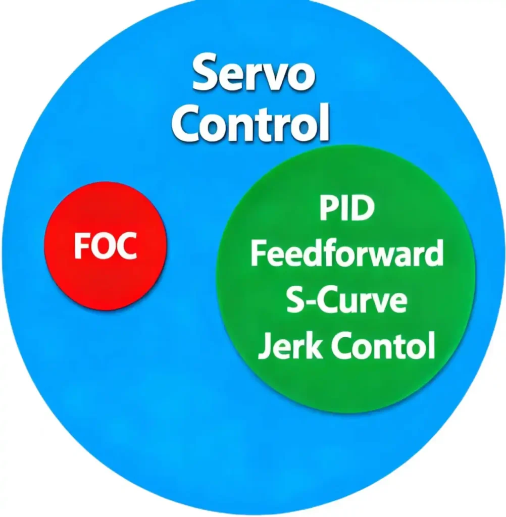
To clarify the concepts we will discuss next—servo control, PID and other algorithms, and FOC—please note:
FOC is an advanced control strategy for servo control, the PID algorithm is the core algorithm to realize closed-loop control in servo control systems, and the three belong to a hierarchical relationship of “control strategy – control system – core algorithm”.
The Role of the Servo Drive
The servo controller (or “drive”) is the “intelligent intermediary” connecting the high-level control (like a PLC or computer) to the motor.
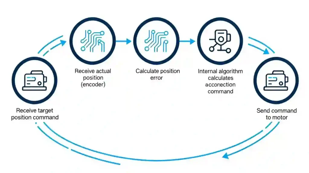
It continuously executes the core servo loop:
- Receive a “target position” command.
- Receive the “actual position” from the encoder.
- Compare the two, calculating the “position error.”
- Using its internal algorithm, calculate a correction command (voltage/current).
- Send this command to the motor.
The speed at which this loop runs—the “servo update rate”—is critical. This rate is typically measured in kilohertz (kHz), meaning thousands of cycles per second (e.g., a 1ms update period is 1kHz). A faster update rate means a faster response to errors, resulting in a “stiffer,” more stable system.
The Benchmark Algorithm:PID
The foundational algorithm for 99% of servo systems is PID (Proportional-Integral-Derivative).
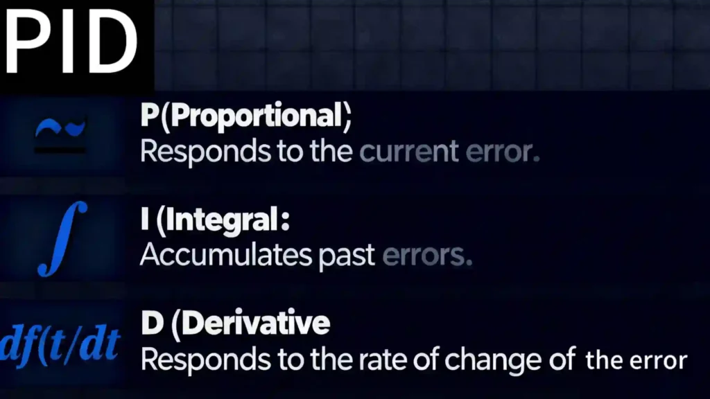
- P (Proportional): Responds to the current error. “The farther I am from the target, the harder I push.”.
- I (Integral): Accumulates past errors. “I’ve consistently failed to reach the target for a while, so I need to add a bit of extra push to compensate.” This is crucial for eliminating small but stubborn steady-state errors.
- D (Derivative): Responds to the rate of change of the error. “I’m approaching the target quickly, I should ‘brake’ early to prevent overshoot.” This provides damping.
These three “gains” (Kp, Ki, Kd) must be finely “tuned” to the system’s specific mechanical characteristics. A poorly tuned loop will cause the system to oscillate, or to react sluggishly and overshoot significantly.
However, PID has a fundamental limitation: it is reactive. It must detect an error, e(t), to generate a correction command. When the system is commanded to move, an error is created (target position ne actual position).
The P term provides a correcting force, but this force causes the motor to lag behind the command. This lag is the “tracking error.” Therefore, a system running on PID alone will always have a tracking error while in motion .
The Proactive Algorithm: Feedforward Control
If PID is reactive, feedforward control is proactive. It uses a mathematical model of the system’s physics to predict the torque required to execute the command before an error even occurs.
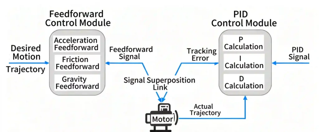
The controller knows the desired motion trajectory, the load’s inertia, and the motor’s characteristics. It pre-calculates the current needed to overcome inertia (acceleration feedforward ), friction (friction feedforward), and gravity (offset feedforward). This signal is “fed forward”and added to the PID’s output.
This is the key to modern high-performance control: the symbiosis of PID and Feedforward. Feedforward handles the “known” physics (e.g., F=ma), while PID handles the “unknown” disturbances.
The controller knows the desired trajectory (e.g., an S-curve), so it knows the desired acceleration a at time t. It can pre-calculate the required force F at time t. The feedforward algorithm sends this pre-calculated current, making the motor follow the command path almost perfectly.
At this point, the tracking error e(t) stays near zero. The PID loop now sees almost no error and only makes minor “fine-tuning” adjustments. This combination drastically reduces tracking error, enabling much higher dynamic accuracy.
S-Curve and “Jerk” Control
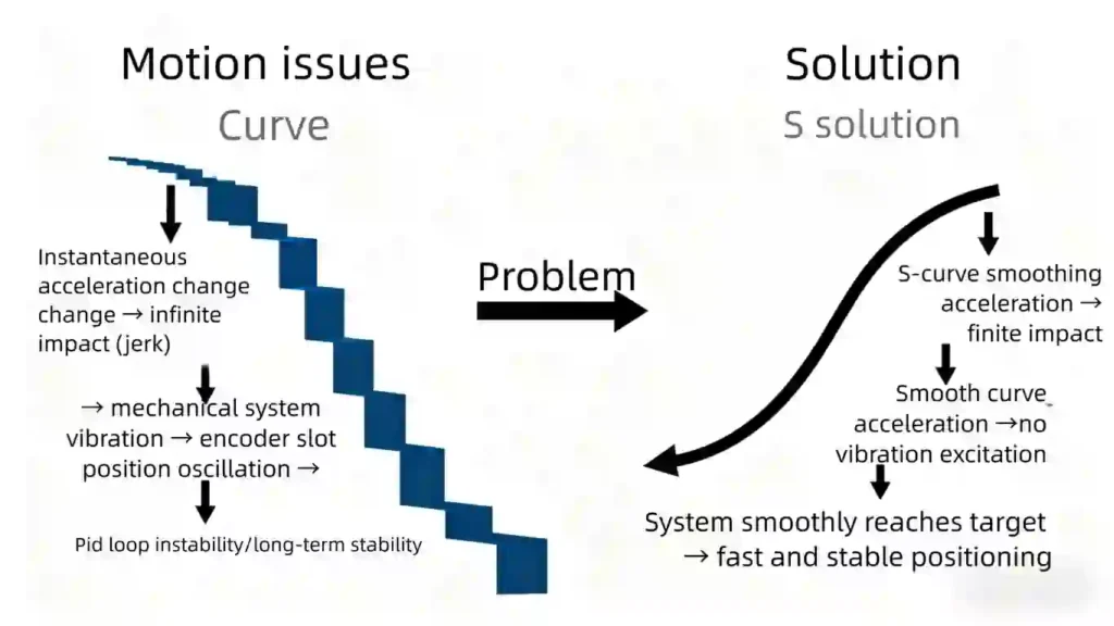
The Problem (Jerk)
A standard “trapezoidal” motion profile (constant acceleration, constant velocity, constant deceleration) has instantaneous changes in acceleration. The derivative of acceleration is known as “Jerk”. This infinite jerk acts like a physical “kick.”
The Solution (S-Curve)
An S-Curve profile achieves motion by smoothly ramping the acceleration up or down. This limits the jerk, creating the characteristic “S” shape on a velocity-time graph.
Smoothness is Precision. It is impossible to hold a sub-degree position if the entire machine is vibrating. The high jerk of a trapezoidal profile “kicks” the mechanical system, exciting its natural resonances and causing vibration. This vibration makes the encoder position oscillate, and the PID loop then (reactively) tries to fight this vibration, leading to instability or a long “settling time” (the time needed for vibration to decay).
An S-Curve applies force gently. It does not excite vibrations. Therefore, the system arrives at the target position smoothly, with minimal overshoot and a very short settling time. An S-curve means faster, more stable positioning.
Field-Oriented Control (FOC)
For coreless BLDC motors, the extremely smooth motion required for sub-degree precision relies on Field-Oriented Control (FOC), also known as vector control.
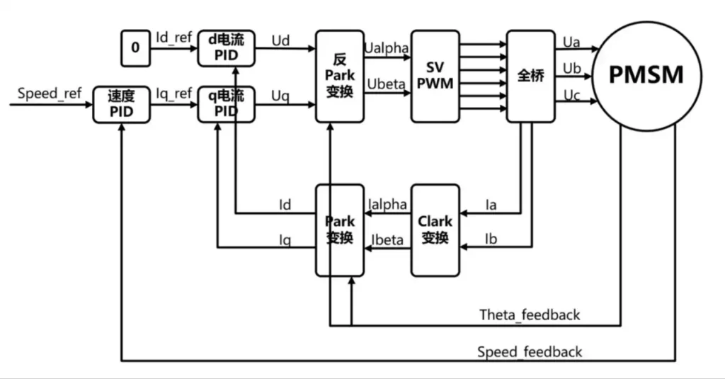
FOC is an advanced strategy that allows for independent control of flux- and torque-producing current, similar to a traditional DC motor. By continuously reading the rotor angle and applying a stator field that is orthogonal (90°) to the rotor field, maximum torque output is achieved.
FOC’s core value is its contribution to precision:
- Eliminates Torque Ripple: FOC can significantly reduce torque ripple, ensuring smoother, more stable operation. This is key to preventing micro-vibrations that degrade sub-degree precision.
- Thermal Management: FOC minimizes energy loss from flux-producing current, improving efficiency and reducing heat. As noted earlier, since thermal stability is key to maintaining precision, FOC serves as a core digital tool for sustaining sub-degree precision in coreless systems.
The System’s Drivers: Electronics and Computing Power
Achieving high-frequency, low-latency, precise control demands dedicated computing hardware and highly optimized drivers.
Processing Power and Low-Latency Requirements
Advanced control schemes like FOC require intensive real-time calculations, including vector transformations and high-frequency loop closure. Historically, this task was handled by Digital Signal Processors (DSPs).
However, modern microcontrollers (MCUs) have integrated hardware DSP support and flexible PWM timers, enabling high-performance MCUs to handle complex motor control tasks.
In high-precision positioning, the system’s final performance is strictly limited by latency. Any delay in angle measurement or command execution translates into tracking error.
For precision applications, low-latency angle measurement times of less than 20µs are required.
DSP in MCUs executes complex FOC algorithms quickly. This reduces latency and maintains high-bandwidth control. This rapid control is essential for achieving sub-degree precision.
PWM Frequency and Driver Technology
Because coreless motors have much lower inductance than iron-core motors, they require higher Pulse Width Modulation (PWM) frequencies (often >30 kHz), with some optimized designs reaching 53 kHz) to smooth the motor current and ensure efficient, quiet operation.
Modern motor drivers are based on smart gate-drive architectures designed to optimize power loss and electromagnetic compatibility (EMC. These drivers often integrate current-shunt amplifiers for real-time monitoring of motor phase currents, which is essential for FOC implementation and system diagnostics.
The Challenge of Precision: Dynamic Tuning and Stability
While coreless motor systems offer the potential for precision in hardware, maintaining sub-degree performance in practice requires overcoming the tuning and stability challenges inherent to low-inertia systems.
Tuning Challenges from Low Rotor Inertia
Due to the extremely low inertia of the coreless rotor, the system is highly sensitive to inputs and disturbances. When tuning the PID loop, high proportional or derivative gains used to achieve high “stiffness” can easily lead to instability, overshoot, and oscillation.
Therefore, compared to high-inertia motors, tuning gains and BEMF (Back EMF) settings must be significantly reduced to ensure stability.
Furthermore, in mechanical transmission design, the ratio of load inertia to motor rotor inertia should be kept close to 1:1 or no more than 5:1 to ensure optimal servo response.
Managing System Resonance and Compliance
The pursuit of high precision is ultimately limited by the physical mechanical system. Coreless motors, especially when coupled with mechanical transmissions or gearboxes, are prone to mechanical resonance and vibration at specific frequencies [34], which is a key limiting factor for precision.
To suppress these high-frequency periodic disturbances (e.g., rotor dynamic imbalance torque) in high-precision applications, specialized control techniques must be employed. For example, introducing a resonance controller (such as one in parallel with a PI controller, forming a PIR control) can improve suppression at the resonant frequency.
Furthermore, mechanical components (shafts, couplings, mounts) inevitably have compliance (i.e., elasticity). This unmodeled mechanical compliance introduces phase lag and reduces overall accuracy.
When mechanical compliance is high, the control system must contend with a system that moves non-linearly. Extreme precision, therefore, depends less on perfecting the inner electrical loops and more on implementing disturbance observers or resonance suppression algorithms that can account for the mechatronic coupled system.
Advanced techniques, such as PI Lead Optimized Translation (PILOT), further improve dynamic accuracy by optimizing motion profiles to reduce error and heat input, seeking to “prevent problems rather than compensate after the fact” .
Application Areas Requiring Sub-Degree Performance
The real-world deployment of coreless servo systems fully demonstrates their ability to achieve sub-degree precision.
Medical and Surgical Robotics
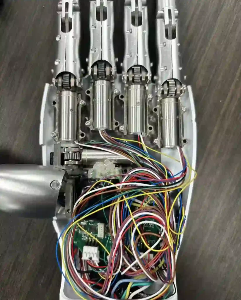
The medical technology field places extreme demands on components, including absolute precision, low vibration, high power density, and low heat generation. Surgical systems, active implants, infusion pumps, and rehabilitation prosthetics all rely on coreless drives.
The high positioning accuracy and cogging-free smooth output of coreless motors make them ideal for robotic arms and surgical tools, ensuring complex motion trajectories and stable joint movement.
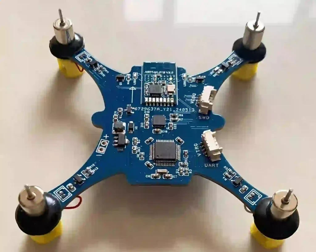
Aerospace and Optical Systems
In the aerospace sector, coreless motors are used in various systems on satellites and spacecraft due to their small size, light weight, and rapid acceleration capabilities. From unmanned aerial vehicles (UAVs) to Mars rovers, hundreds of drive systems are required to maintain high precision even in extreme environments.
In industrial automation, especially in fields with extreme positioning demands like optical systems, lab automation, and semiconductor manufacturing, coreless drives are indispensable. These applications require component positioning accuracy at the micrometer or sub-degree level to meet the precision demands of Industry 4.0’s complex mechatronic systems.
Conclusion: Synthesis of a High-Precision Ecosystem
Coreless motors are undoubtedly capable of precise control “within degrees,” as this level of precision is trivial for modern servo technology. The true engineering challenge lies in achieving and maintaining sub-degree precision below 0.1°.
Achieving world-class angular precision requires a highly integrated, meticulously tuned mechatronic system built upon four interdependent, critical elements:
- Motor Architecture: A coreless BLDC motor must be selected to fundamentally eliminate cogging and maximize dynamic response via its low-inertia design.
- Feedback System: A high-resolution absolute encoder (15-bit or higher) must be used, selecting a technology (like inductive or ruggedized magnetic) that is robust in the actual operating environment and directly integrated onto the motor shaft.
- Advanced Control: The control engine must execute on a low-latency MCU or DSP, utilizing cascaded FOC algorithms. The FOC must operate at a high PWM frequency to ensure minimal torque ripple and smooth current.
- Dynamic Management: Rigorous dynamic tuning and advanced compensation strategies, such as resonance controllers, temperature compensation, and advanced predictive control techniques, must be implemented to address the instability inherent in low-inertia systems and errors introduced by mechanical compliance.
Future trends will continue to focus on increasing the integration of electronic systems, especially the integration of DSP/FOC functionality into more compact motor drive chips.
Concurrently, advanced predictive and feedforward control algorithms will become increasingly vital for dynamically compensating for mechanical compliance and thermal drift, pushing sustained angular precision into the finer realms of arc-minutes and arc-seconds.
Frequently Asked Questions (FAQ)
Q1: Can coreless motors really be controlled to within 1 degree?
A1: Yes, not only is it feasible, but “degree-level” control is a benchmark requirement for modern mechatronic systems. For today’s precision systems, the real focus is on sub-degree accuracy (e.g., 0.1°) or even higher, at the arc-minute or arc-second level.
Q2:If I use a coreless motor, will I automatically get high precision?
A2:No. High precision cannot be achieved by a single component like the motor. It requires a “precision ecosystem” where five key elements work together. The final positioning accuracy is not determined by the motor itself, but by the quality of the feedback device (encoder) and its integration with the control system
Q3:Why are coreless motors better for precision control than traditional iron-core motors?
A3:The key advantage lies in their ironless structure:
- Linear Characteristics: Torque is strictly proportional to current, and speed to voltage. This “predictability” greatly simplifies control modeling.
- Elimination of Cogging: They have no magnetic “detent” (cogging torque). This ensures smooth, even motion even at very low speeds.
- Extremely Low Inertia: The rotor is lightweight, giving it minimal inertia. This allows for extremely high dynamic response and rapid acceleration.
Q4:What are the main challenges in using a coreless motor for high precision?
A4:The biggest challenge comes from its extremely low rotor inertia.
- Mechanical Limits: The system’s final precision is limited by physical mechanical resonance and component “compliance” (i.e., elasticity). Advanced algorithms like resonance controllers are needed to actively compensate for these physical limitations.
- Tuning Difficulty: The low-inertia system reacts very strongly to inputs and disturbances. High control gains (like in PID) used to achieve “stiffness” can easily cause the system to become unstable, oscillate, and overshoot.
TSL Motor: Custom DC Motor Solutions
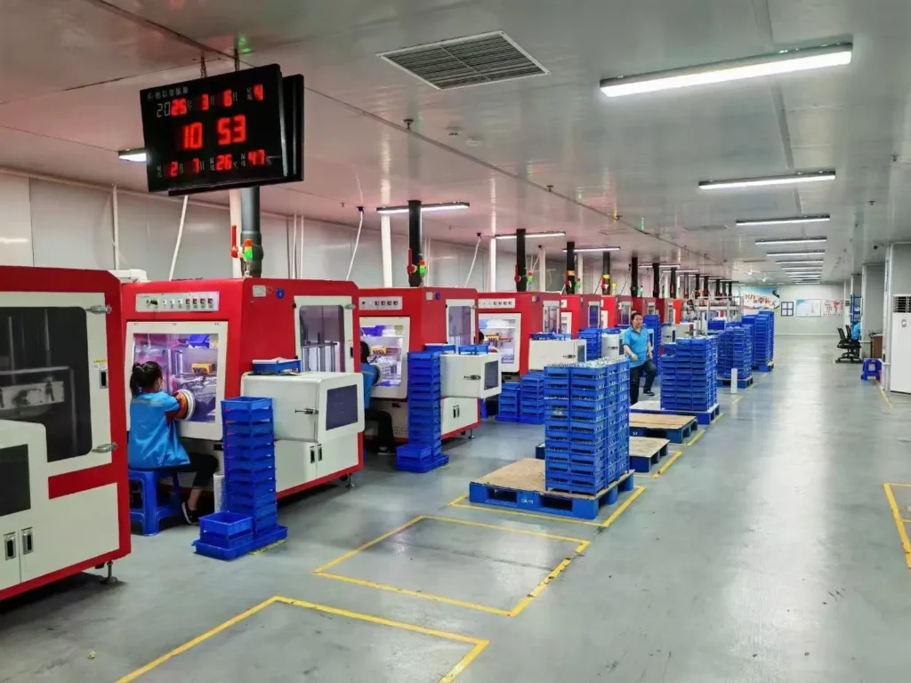
Established in 2009, Tsinglin Motor has evolved into a leading innovator in precision drive systems and specialized motor manufacturing. Our 15,000㎡ advanced production facility in Shenzhen houses a skilled workforce of 200+ professionals, delivering an annual output of 2 million units to global markets.
Continuous R&D investment in energy-efficient motor technologies
Lean manufacturing processes ensuring cost-competitive pricing
Agile production capacity scaling for batch customization
Global compliance certifications (CE, RoHS, REACH)
With dual focus on operational excellence and client success, Twin Motor empowers businesses worldwide to achieve technological differentiation. Our engineering team welcomes complex challenges across automotive, robotics, and smart infrastructure applications.
Contact our solutions center to discuss your project requirements or request our technical portfolio.
TSL Micro DC Motor
-
 Custom Micro Motors12 products
 - DC Gear Motor162 products
- 6mm Planetary Gear Motor4 products
- 6mm Planetary Metal Gear Motor3 products
- Brushless Gear Motor34 products
- Micro Gear Motor87 products
- Coreless Gear Motor32 products
- N20 Gear Motor26 products
- Plastic Gearbox Motor9 products
- Standard Gear Motor15 products
- Stepper Gear Motor16 products
-
- Planetary Gear Motor52 products
- Spur Gear Motor63 products
- Worm Gear Motor32 products
-
- DC Motor81 products
- Brushed DC Motor17 products
- Brushless DC Motor36 products
- Inrunner Rotor BLDC Motor8 products
- Outrunner Rotor BLDC Motor26 products
-
- Coreless DC Motor14 products
- Micro DC Motor16 products
-
- Dexterous Hand Drive Module19 products
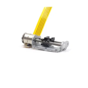
- Micro Linear Actuators6 products
- Stepper Motor32 products
- Micro Stepper Motor13 products
- NEMA Stepper Motor9 products
- Stepper Motor Linear Actuator11 products
-
- Vibration Motors71 products
- Brushless Vibration Motor8 products
- Coin Vibration Motor22 products
- Coreless Vibration Motor3 products
- Encapsulated Vibration Motor6 products
- Linear Resonant Actuator12 products
- Powerful Vibrating Motor17 products
- SMD Vibration Motor4 products
- Sonic Vibration Motor2 products
-