Published: JANUARY 31, 2025
Updated:October 6, 2026
When a standard stepper motor cannot meet the high-torque requirements at low speeds, or when finer displacement control is needed, a geared stepper motor becomes the optimal upgrade solution.
By perfectly combining a stepper motor with a gearbox, this Getriebeschrittmotor reduces speed while giving the system greater “power” and more precise positioning, effectively addressing the low-speed vibration issue of stepper motors.
Without complex closed-loop control, it can achieve robust and predictable motion at low cost. This guide aims to give you a comprehensive understanding of this configuration and help you make precise selections in real projects.
Wichtigste Erkenntnisse
- It integrates a stepper motor and a gearbox. It delivers high torque at low speeds and precise positioning at low cost.
- It amplifies torque proportionally without enlarging the motor size. It saves installation space for heavy-load drives.
- Gear ratio reduces the equivalent step angle. It greatly improves positioning resolution.
- It damps low-speed resonance and jitter. It lowers step loss by cushioning load shocks.
- Various motor and gearbox types match different working conditions.
- Key selection factors: gear ratio, pull-out torque, step angle and installation size.
- It is a cost-effective choice, but has backlash, speed limits and transmission loss.
Why Add a Gearbox to a Stepper Motor?
In many applications, using a Schrittmotor alone is often not the optimal solution. While stepper motors have advantages such as simple structure, easy control, and precise positioning, they have inherent limitations in low-speed high-torque performance, smooth operation, and high-resolution positioning.
Adding a gearbox to a stepper motor to form a Getriebeschrittmotor essentially amplifies the motor’s advantages while compensating for its shortcomings.
More Output Torque Within a Limited Space
The output torque of a stepper motor is closely related to its size. Larger motors generally provide higher torque. Simply increasing the motor size to gain torque not only significantly increases installation space requirements but also makes the overall size and weight much larger.
Compared with adding a gearbox, this approach usually requires a much bigger motor to achieve the same output.
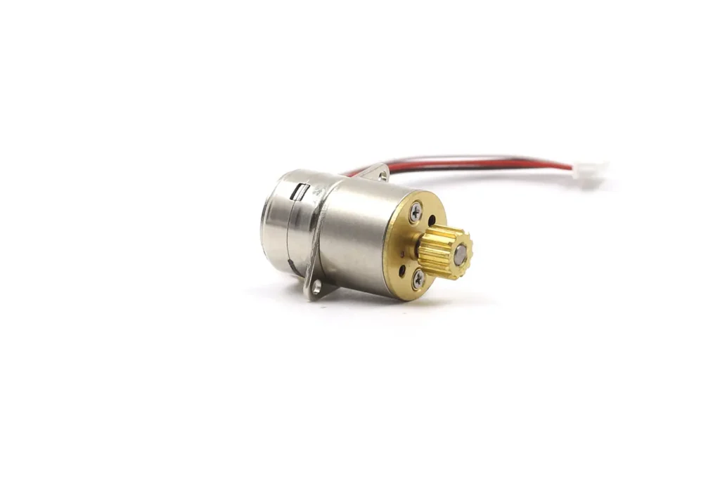
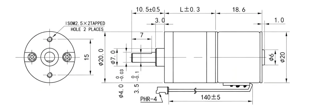
By adding a gearbox, the output torque can be proportionally amplified without changing the motor size, allowing a small stepper motor to drive larger loads stably. This provides better performance and structural layout in space-constrained applications.
Better Matching Between the Motor and the Load
A gearbox reduces the load inertia reflected to the motor. This can give the stepper motor more acceleration margin and make a high-inertia load easier to start, stop and reverse.
The gearbox also adds its own inertia, friction, backlash and torsional compliance. For this reason, the result should be evaluated from the complete motion profile rather than from static torque alone. Acceleration, deceleration, load variation and reversing frequency can be just as important as the nominal operating point.
Improved Positioning Resolution
After a gearbox is added, each motor step produces a smaller angular movement at the output shaft. This provides finer theoretical output resolution and can be useful for indexing, valve adjustment and other low-speed incremental motions.
Adding a gearbox reduces the effective output step angle according to the gear ratio. For example, an 18° permanent-magnet stepper motor with a 10:1 reduction can achieve an effective step angle of 0.047°.
However, resolution and accuracy are not the same. Actual output positioning is also affected by gearbox backlash, gear errors, shaft deformation, microstep nonlinearity, load torque and possible missed steps. A gearbox can make the commanded movement finer, but it cannot guarantee that the load reaches the same mechanical position from both directions.
Reduced Resonance and Vibration
Stepper motors are prone to resonance and vibration at low speeds due to interactions between rotor inertia and the periodic variation of electromagnetic torque. This effect is more pronounced with higher loads or system inertia, resulting in increased vibration and unstable motion.
The mechanical inertia and damping introduced by the gearbox help smooth the rotation at the output shaft, reducing vibration and noise during low-speed operation. This is especially suitable for applications requiring long-term, continuous low-speed operation.
Reduced Risk of Missed Steps
Directly driving a load can cause stepper motors to miss steps when torque is insufficient, which is usually undetected in open-loop systems.
By using a gearbox to reduce the direct load impact on the motor, the motor’s disturbance resistance increases, significantly lowering the risk of missed steps under the same conditions and improving overall system reliability.
Optimized Cost-Performance Balance
For many low-speed high-torque applications, using a servo motor might otherwise be considered. However, servo systems have higher costs, complex tuning, and integration requirements.
A Getriebeschrittmotor provides a cost-effective compromise: it simplifies the system while meeting application requirements, offering controllable costs without sacrificing performance.
Geared Stepper Motor Structure
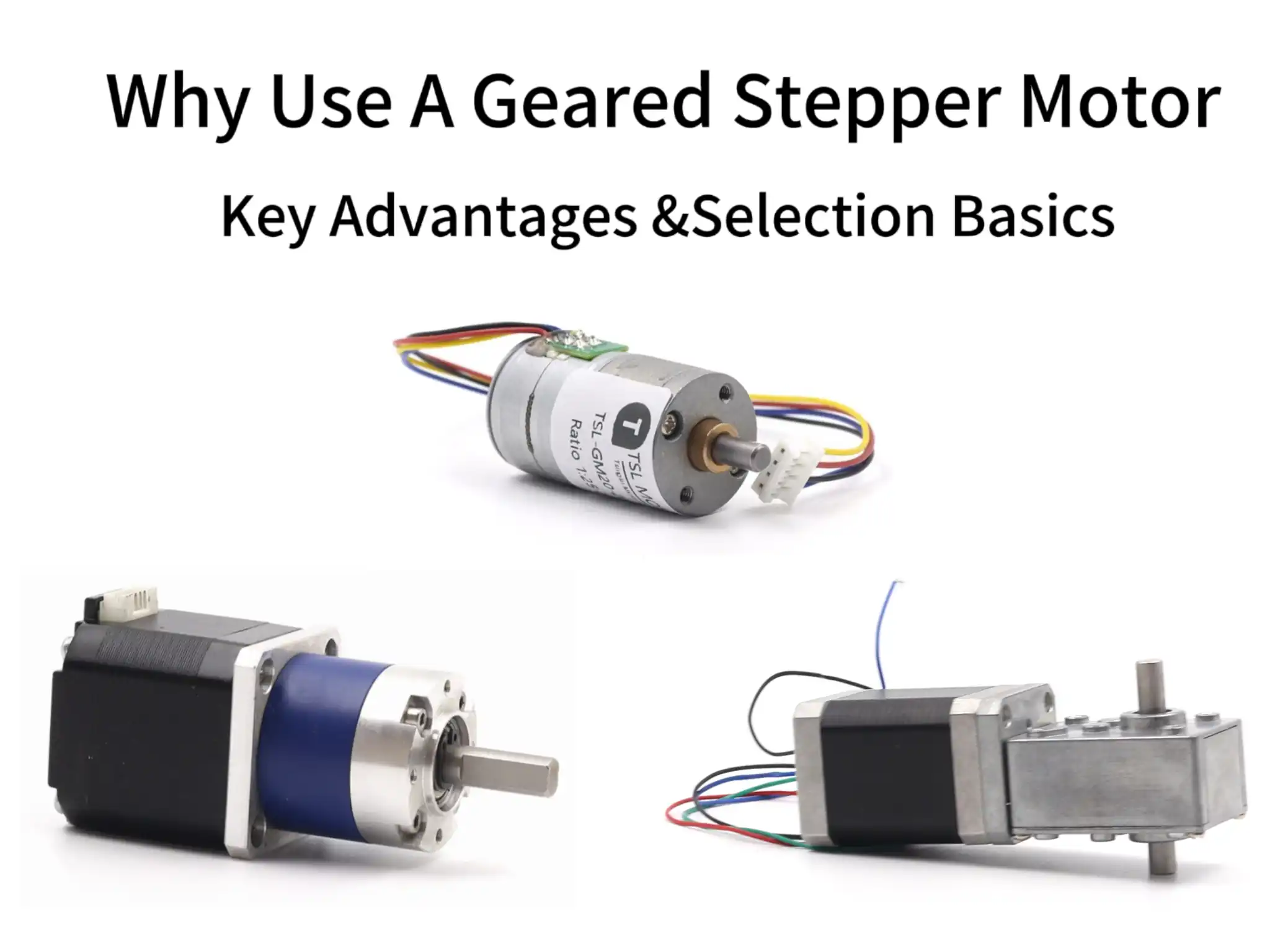
Structurally, a geared stepper motor consists mainly of the stepper motor itself and the gearbox.
Stepper motors generally include permanent-magnet (PM), variable-reluctance (VR), and hybrid types. Gearboxes can be planetary, spur, or worm gear types, with different combinations providing distinct performance characteristics and application scenarios.
Stepper Motor Types
Although permanent-magnet, variable-reluctance and hybrid stepper motors all exist, most compact geared stepper motors used in current commercial equipment are based on permanent-magnet or hybrid designs.
| Stepper Motor Type | Main Characteristics | Design Limitations | Typical Applications |
|---|---|---|---|
| Permanent-magnet stepper motor | Compact, economical and suitable for high-volume production | Larger native step angle and limited high-speed performance | Valves, air dampers, office equipment and consumer mechanisms |
| Hybrid stepper motor | Smaller native step angle, higher torque capability and better dynamic control | Higher cost, greater axial length and higher driver-current requirements | Automation equipment, positioning systems, robotics and instruments |
| Variable-reluctance stepper motor | Low rotor inertia and no permanent magnet in the rotor | Limited unpowered holding capability and uncommon in modern compact gearmotors | Specialized indexing and legacy industrial mechanisms |
Permanent-Magnet Stepper Motor (PM)
PM stepper motor:The rotor uses permanent magnets, and the stator has a salient-pole winding structure without fine-tooth design. The rotor is driven directly by the magnetic attraction/repulsion between the stator magnetic field and the rotor magnets.
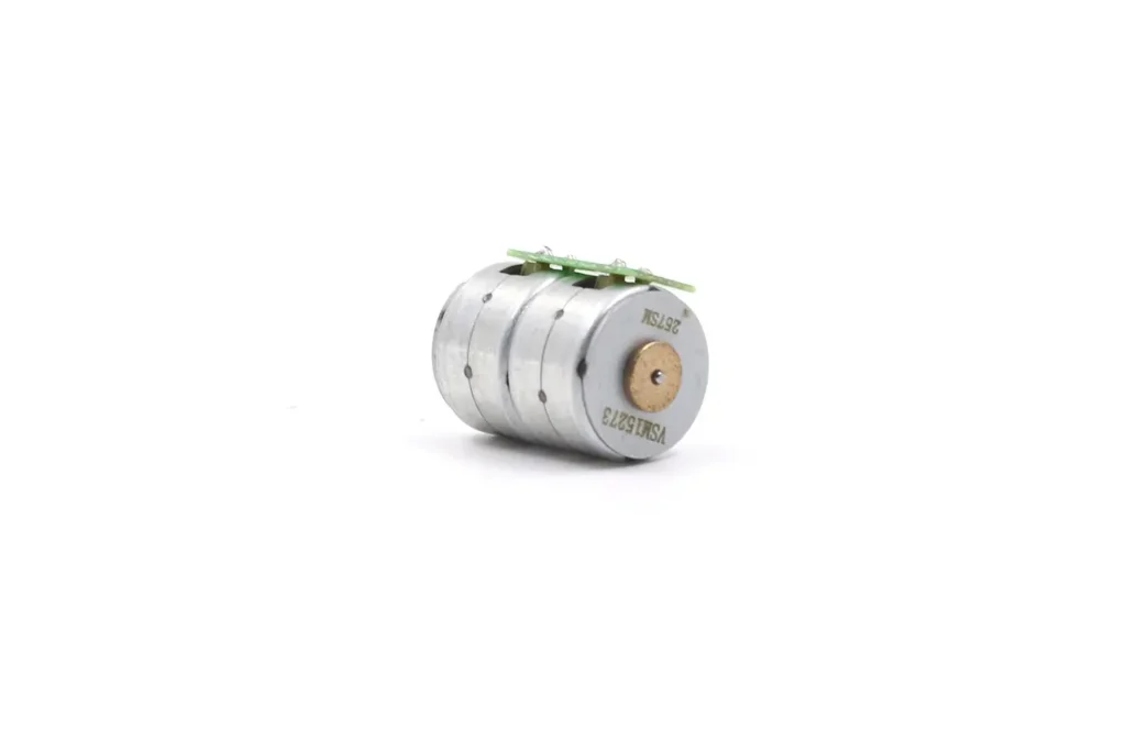
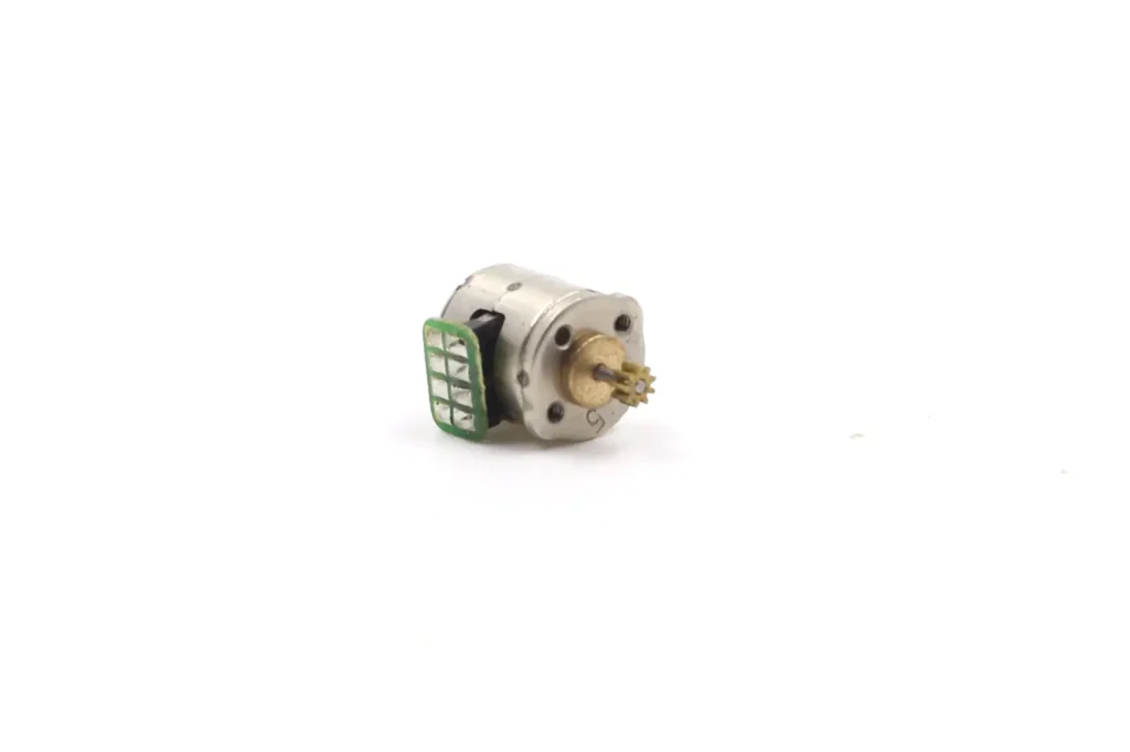
- Step angle: Typically 7.5° or 18°
- Characteristics: Simple structure, low cost, low power consumption, high holding torque, self-locking when powered off; poor high-speed performance, low torque, low precision.
- Typical applications: Low-precision instruments, toys, simple valves, paper feed mechanisms in office equipment, light-load scenarios.
Variable-Reluctance Stepper Motor (VR)
VR stepper motor:The rotor is made of soft magnetic material with a salient-pole structure and no magnets. The stator has a corresponding fine-tooth design. The rotor moves to the position of minimum magnetic reluctance when the stator is energized.
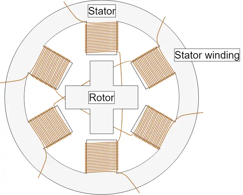
- Step angle: 1.8° or 3.75°
- Characteristics: Simple, low manufacturing cost, low rotor inertia, good high-speed response; no self-locking when powered off, moderate torque, moderate precision, vibration and noise may be noticeable.
- Typical applications: Early automation machines, low-cost machine tool axes, low-speed textile and packaging machines, old office equipment, simple indexing mechanisms; being gradually replaced by hybrid motors.
Hybrid Stepper Motor(HB)
Hybird stepper motor:The rotor combines permanent magnets with fine teeth, and the stator has matching fine teeth. The rotor is driven by both magnetic attraction/repulsion and variable reluctance effects.
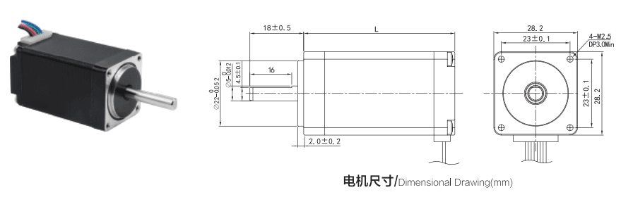
- Step angle: Typically 1.8°, further reducible with microstepping
- Characteristics: Moderate-to-high structural complexity, higher cost; high torque, smooth operation, low vibration and noise at low speed, good high-speed performance, high positioning precision, self-locking, compatible with microstepping.
- Typical applications: 3D printers, CNC machines, engraving machines, precision transmission modules, robotic joints, medical testing equipment, surveillance PTZ, semiconductor tooling, precise printing/packaging applications.
Gearbox Types
The gearbox should be selected according to the required shaft arrangement, torque density, efficiency, noise, backlash, load direction and service life.
| Gearbox Type | Output Arrangement | Main Advantages | Main Design Considerations |
|---|---|---|---|
| Spur gearbox | Parallel-axis stages; output may be coaxial or offset | Simple construction, flexible layout and controlled production cost | Backlash and noise may accumulate across multiple stages |
| Planetary gearbox | Normally coaxial with the motor | High torque density, compact diameter and distributed gear loading | Carrier, planet pins and ring-gear accuracy strongly affect performance |
| Worm gearbox | Normally a right-angle output | Large reduction in a compact stage and possible resistance to back-driving | Lower efficiency, sliding wear and temperature rise require attention |
Planetary Gearbox
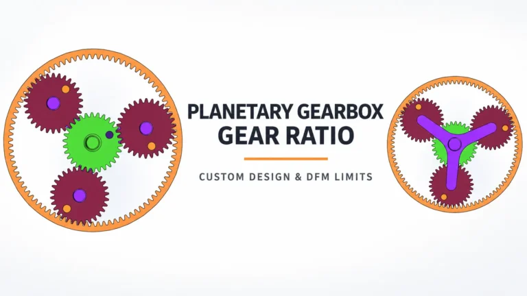
A planetary gearbox consists of a sun gear, planet gears and an internal ring gear. The planet gears rotate around the sun gear and drive the ring gear for output.
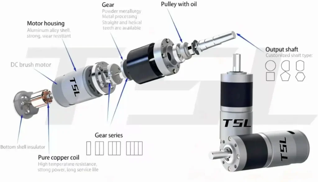
- Advantages: High efficiency, compact, uniform load distribution
- Anwendungen: High-torque, coaxial output, space-constrained industrial automation; most commonly used type.
More information is available in the planetary gear motor design guide.
Spur Gearbox
A spur gearbox is composed of one or more pairs of spur gears, achieving deceleration through gear meshing.
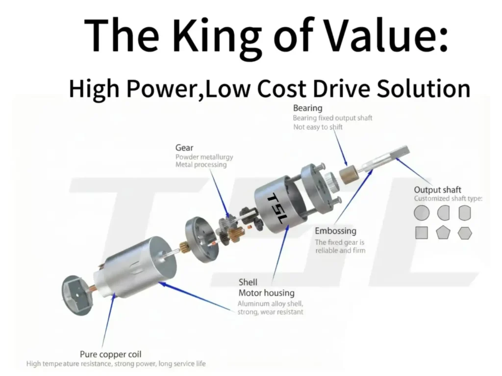
- Advantages: Simple, easy to manufacture, low cost, relatively high efficiency
- Limitations: Limited load capacity, higher noise during engagement
- Anwendungen: Light-load, low-cost devices, non-space-constrained situations.
Worm Gearbox
A worm gearbox consists of a worm (helical shaft) and a worm gear. The worm drives the worm gear to rotate for deceleration.
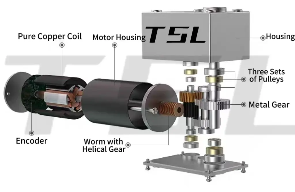
- Advantages: High reduction ratios, self-locking output
- Limitations: Lower efficiency, potential heat generation under long-term heavy load
- Anwendungen: Anti-reverse or holding applications like valve control, lifting mechanisms, precision positioning.
Limitations of Geared Stepper Motors
Despite numerous advantages, the following limitations should be noted when selecting a geared stepper motor:
Backlash
Backlash is an inevitable mechanical meshing clearance inside the gearbox of a geared stepper motor (especially in worm gear and multi-stage planetary gear structures).
Simply put, it is the maximum angle (or displacement) that the output shaft can rotate freely when the input shaft of the gearbox is fixed, essentially the tiny gap between meshing components such as gears and worms.
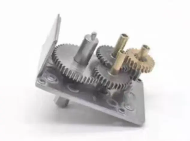
For high-precision reciprocating positioning or scenarios requiring micron-level repeatability, such clearance may lead to the accumulation of positioning errors.
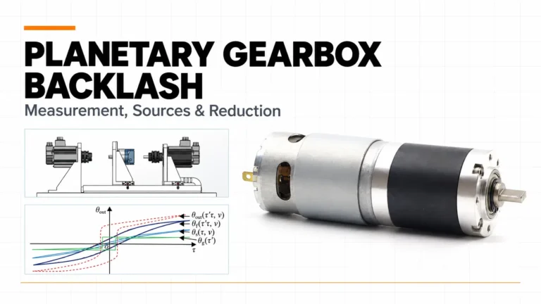
Software can compensate for relatively stable reversing offsets, but it cannot eliminate physical clearance or fully correct backlash that changes with load, temperature, lubrication and wear. An output-side encoder can observe the resulting position difference, but it does not physically remove the clearance. Detailed measurement methods are explained in the planetary gearbox backlash guide.
Limited Output Speed and Dynamic Torque
A geared stepper motor is primarily intended for low-speed output. When a higher output speed is required, the stepper motor must operate at a correspondingly higher internal speed and pulse frequency.
Stepper-motor torque normally decreases as speed rises because winding inductance limits how quickly phase current can build. At sufficiently high speed, back EMF and insufficient current rise time can sharply reduce available torque. A motor selected only from holding torque may therefore stall during acceleration or high-speed operation.
The correct check is the available pull-out torque at the motor’s actual operating speed, with additional margin for acceleration, gearbox losses and load variation.
Engineering suggestions: Select an appropriate gear ratio according to load and speed requirements, and evaluate the system responsiveness after deceleration.
Transmission Efficiency Loss
Gear meshing, bearings, shaft seals and lubricant movement all consume energy. The resulting loss appears mainly as heat inside the motor–gearbox assembly.
Spur and planetary gearboxes generally use rolling-dominant tooth contact and can provide relatively high efficiency when correctly manufactured and lubricated. Worm gearboxes involve more sliding contact, so their efficiency and temperature are more sensitive to load, material pairing, lubrication and continuous operating time.
Motor copper loss and gearbox loss must be considered together. A combination that operates safely for a short indexing cycle may overheat during continuous operation, even when neither component exceeds its short-duration torque limit.
Engineering suggestions: Design the gear ratio reasonably, and pay attention to lubrication and heat dissipation conditions.
Wear and Service-Life Variation
Gear teeth, bearings, shafts and lubricant all change during operation. Wear can increase backlash, reduce transmission efficiency and alter noise over time.
Frequent reversing, shock loading, excessive output-shaft loads, insufficient lubrication and operation above the rated temperature can accelerate this process. A gearbox that survives a static torque test may still have insufficient life under millions of start–stop or forward–reverse cycles.
Service-life validation should therefore reproduce the intended load, speed, duty cycle, mounting direction and ambient temperature as closely as possible.
Service-life validation should therefore reproduce the intended load, speed, duty cycle, mounting direction and ambient temperature as closely as possible.
Engineering suggestions: Select high-precision materials, conduct regular lubrication inspections, and make reasonable selections according to load characteristics.
Lärm und Vibration
The vibration generated by a geared stepper motor comes from both electromagnetic stepping and mechanical gear engagement. Motor torque ripple, gear-mesh frequency, shaft alignment, housing stiffness and mounting resonance can interact with each other.
Microstepping can reduce abrupt electromagnetic torque changes, but it cannot correct gear-profile errors, eccentricity, backlash impact or structural resonance. Similarly, plastic gears may reduce gear-mesh noise, but their load capacity, temperature resistance, creep and wear must still satisfy the application.
Noise should be tested with the final mounting structure because a motor that sounds quiet on a test bench may excite a thin panel, bracket or equipment housing after installation.
Engineering suggestions: For noise-sensitive occasions, low-noise designed planetary gearboxes or plastic gears can be selected.
Comparison Between Geared Stepper Motors and Other Motor Solutions
Geared stepper motors offer clear advantages over conventional motors. They provide better torque and higher positioning accuracy. They also feature simpler control logic and lower overall costs.
Comparisons with mainstream motor types are elaborated item by item below:
| Drive Solution | Main Strength | Main Limitation | Suitable Applications |
|---|---|---|---|
| Direct-drive stepper motor | Simple structure, no gearbox backlash and higher available output speed | Limited output torque and load-inertia capability | Light-load indexing and short positioning movements |
| Geared stepper motor | Higher output torque, finer mechanical movement and compact drive size | Lower output speed, gearbox backlash and mechanical wear | Low-speed indexing, valves, instruments and compact automation |
| DC gear motor | Smooth continuous rotation and simple speed control | Accurate position control normally requires an encoder | Pumps, conveyors, adjustment mechanisms and continuous drives |
| Servo motor | Wide speed range, fast response and closed-loop disturbance correction | Higher control cost and more demanding tuning | High-speed positioning, variable trajectories and dynamic automation |
Geared Stepper Motor vs. Direct-Drive Stepper Motor
A direct-drive stepper motor is normally preferable when it can provide sufficient dynamic torque at the required speed without exceeding the available installation space. Eliminating the gearbox avoids transmission loss, mechanical backlash, additional noise and gearbox wear.
A geared stepper motor becomes more practical when a larger direct-drive motor cannot fit, when the load inertia is difficult to accelerate reliably, or when the mechanism requires slow and controlled incremental output. The decision should be based on the motor’s dynamic torque curve rather than holding torque alone.
Geared Stepper Motor vs. DC Gear Motor
A DC gear motor is naturally suited to continuous rotation. Its speed can be controlled by voltage or PWM, and it can provide smooth motion without receiving a pulse for every commanded position increment.
A geared stepper motor is more convenient when the mechanism repeatedly moves between defined positions and the load remains predictable enough for open-loop control. However, it can lose synchronization when the available torque is exceeded, while a basic DC gear motor cannot determine its absolute or relative position without additional feedback.
Once an encoder and closed-loop controller are added to the DC gear motor, the comparison changes. Selection must then consider encoder position, control bandwidth, motor life, gearbox backlash, cost and the required positioning performance of the complete system.
Geared Stepper Motor vs. Servo Motor
Servo Motors:Servo motors offer elite speed and precision. They use closed-loop control for ultra-precise positioning. However, the hardware is expensive. Setting them up requires complex tuning, impedance matching, and high technical expertise.
Geared Stepper Motors:Geared stepper motors are much more affordable and easier to control. While not as fast as servos, they provide stable torque for most mid-range tasks. They are perfect for low-speed, high-torque applications.
The Bottom Line:If your project is cost-sensitive and doesn’t need extreme speed, geared steppers are the best choice. They shorten development cycles and simplify debugging.
Selection of Geared Stepper Motors
Geared stepper motor selection should begin with the required output motion rather than a preferred motor size. Define the output speed, operating torque, short-duration peak load, duty cycle, positioning requirement and available installation space before comparing motor and gearbox combinations.
Übersetzungsverhältnis
The gear ratio is a key parameter in geared stepper motors. It directly affects output speed and torque: a higher ratio increases torque but reduces speed, while a lower ratio decreases torque but increases speed.
When selecting, match the gear ratio precisely to the load’s required speed and torque to ensure sufficient torque and meet speed demands.
Kippmoment
Pull-out torque is the maximum load torque a motor can stably deliver under rated conditions and serves as the key indicator for determining whether the motor can drive the target load. If the load torque exceeds this value, the motor may lose steps, stall, or suffer positioning errors.
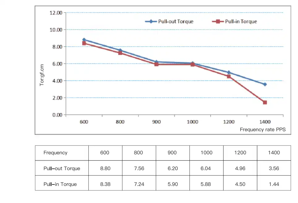
Therefore, during selection, the motor’s pull-out torque must include a reasonable safety margin to handle load fluctuations and sudden impacts.
Schrittwinkel
The step angle is the rotor’s rotation per pulse and determines the motor’s positioning accuracy—the smaller the step angle, the higher the resolution. In a geared stepper motor, the gearbox further enhances positioning accuracy.
During selection, the step angle and gear ratio should be matched to the application’s accuracy requirements to meet the desired positioning error range.
Detent Torque and Holding Torque
Detent torque (or static positioning torque) is the rotor’s inherent holding force when the motor is unpowered, allowing basic positioning after power loss.
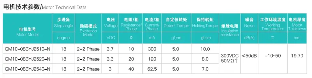
Holding torque is the motor’s ability to resist external forces when energized but stationary, ensuring positioning stability under static loads—especially critical for vertical loads or long-term shutdown positioning.
Motor Size and Installation Space
Selection should consider the available space in the equipment assembly cavity and match installation interfaces—such as flange specifications and shaft diameter—to ensure smooth motor installation and allow adequate maintenance clearance.
An oversized motor may not fit, while an undersized one may lack sufficient torque or operate unstably.
Excitation Mode and Insulation Resistance
The excitation mode—such as unipolar or bipolar—directly influences the motor’s torque output, power consumption, and operating noise, and should be chosen based on control performance and energy efficiency requirements.
Insulation resistance affects electrical safety and service life, and must meet the application’s electrical safety standards to prevent faults like short circuits or leakage due to inadequate insulation.
Customization Directions of TSL MOTOR Geared Stepper Motors
TSL Motor normally begins with an existing motor and gearbox platform, then adjusts the parts that directly affect the customer’s application. This approach can reduce tooling cost, sample-development time and validation risk compared with developing every component from the beginning.
Core Performance Parameter Customization
Non-standard gear ratios can be customized to match load speed and torque needs. Motor voltage and no-load torque can also be tailored for different power supplies and loads—preventing performance waste or power shortages from mismatched standard specs.
Output Shaft Customization
Output shaft shape (e.g., D-shaft, spline, flat), diameter, and length can be customized to optimize shaft-end connections, enhance motor-equipment compatibility, and reduce the need for extra adapters—saving design effort and cost.
Control Mode Upgrade Customization
Encoders can be integrated to upgrade from open-loop to closed-loop control—eliminating step loss and positioning errors, boosting accuracy and stability for high-precision applications like precision instruments and advanced automation equipment.
Gear Structure Customization
For noise-sensitive and long-life applications, motors can be customized with low-noise gears (e.g., precision-ground or silent gear sets) to reduce operational noise, and with durable gear materials and lubrication systems to extend service life—ideal for continuous-operation environments like assembly lines.
Installation and Housing Customization
Special flanges—like non-standard hole patterns, custom shapes, or varied mounting sizes—can be tailored for tight installation spaces. Housing materials (e.g., corrosion- or heat-resistant), protection ratings, and structural designs can also be customized for harsh environments like high humidity, dust, or extreme temperatures.
In short, TSL MOTOR’s geared stepper motors deliver targeted customization from a proven standard platform—addressing real-world application challenges while balancing performance, reliability, and cost for efficient, stable operation across industries.
Zusammenfassung
A geared stepper motor combines a stepper motor with a gearbox to deliver low-speed high torque, precise positioning, and smooth operation. It overcomes common issues of standard stepper motors—like low torque, vibration, jitter, and step loss under heavy loads—while offering a cost-effective, easy-to-control solution.
During selection, key parameters—including gear ratio, pull-out torque, step angle, holding torque, and motor size—must be carefully matched to the application for optimal reliability.
With TSL MOTOR’s customization options—such as output shaft shape, gear design, control mode (e.g., open-loop to closed-loop), and installation interface—performance and compatibility can be further enhanced.
Overall, geared stepper motors are ideal for low-speed, high-torque, high-precision applications, delivering stable, efficient, and controllable motion—making them essential for precision industrial automation.
FAQ
Q1: What is a Geared Stepper Motor?
A Geared Stepper Motor combines a stepper motor with a gearbox to reduce speed, increase torque, and improve positioning accuracy.
Q2: Why use a Geared Stepper Motor?
It provides higher torque at low speed, smoother motion, and finer positioning without increasing motor size.
Q3: Does the gearbox improve positioning accuracy?
Yes. The gearbox reduces the effective step angle, significantly increasing output resolution.
Q4: What are the main limitations?
Backlash, lower maximum speed, and efficiency loss at high reduction ratios.
Q5: Can Geared Stepper Motors be customized?
Yes. Gear ratio, shaft design, voltage, gearbox type, and encoders can all be customized.

Schrittmotor mit Getriebe
TSL MOTOR designs stepper gear motors with flexibility, allowing customization to suit any equipment need. They offer a range of standard models, including versions with gearboxes and encoders.