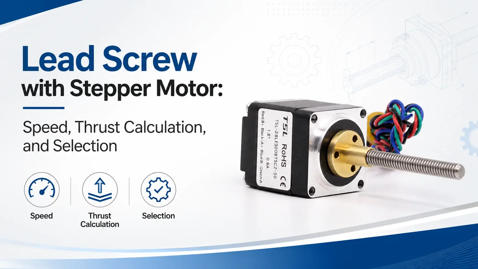
A lead screw with stepper motor should not be selected only by motor size, rated current, or holding torque. In a real machine, several points must be confirmed. Can the actuator provide enough thrust at the target speed? Can it reach the required resolution? Will the lead screw whip or buckle? Is there a risk of back-driving in a vertical installation?
After the lead screw type, lead, diameter, and structure are selected, more calculations are required. These include linear speed, travel per step, load thrust, and dynamic motor torque.
This article explains the main engineering calculations and selection logic for a lead screw with stepper motor.
Key Takeaways
- Calculate linear speed from motor RPM and screw lead.
- Check dynamic torque at the target operating speed.
- Use screw lead to estimate positioning resolution.
- Calculate thrust with torque, lead, and efficiency.
- Include friction, acceleration, and external loads.
- Check critical speed, buckling, and back-driving risk.
- Select the lead screw with stepper motor as a complete system.
How to Calculate Linear Speed
The linear speed of a lead screw with stepper motor mainly depends on motor speed and screw lead. Use the following formula:
v = n × L ÷ 60
Where:
- v is linear speed, in mm/s;
- n is motor speed, in rpm;
- L is lead screw lead, in mm/rev.
For example, the motor speed is 600 rpm and the screw lead is 2 mm. The linear speed is:
v = 600 × 2 ÷ 60 = 20 mm/s
This means the mechanism can theoretically move 20 mm per second. Load and mechanical losses are not included.
If the target linear speed is known, the required motor speed can also be calculated:
n = 60v ÷ L
For example, the target speed is 40 mm/s with a 2 mm lead screw:
n = 60 × 40 ÷ 2 = 1200 rpm
If an 8 mm lead screw is used instead:
n = 60 × 40 ÷ 8 = 300 rpm
Both designs can reach 40 mm/s. However, the motor operating conditions are very different.
A 2 mm lead requires 1200 rpm. An 8 mm lead requires only 300 rpm. Stepper motor torque decreases as speed rises. Therefore, the first design may not provide more actual thrust.
The speed formula only shows the required speed. It does not prove that the motor can run reliably.
After calculation, check the motor speed-torque curve at that speed. Make sure the remaining torque can overcome the load, friction, and acceleration demand.
Linear Travel per Step and Theoretical Resolution
The number of full steps per motor revolution can be calculated as follows:
N = 360° ÷ step angle
For a common 1.8° stepper motor:
N = 360° ÷ 1.8° = 200 steps/rev
The theoretical linear travel for each full step is:
S = L ÷ N
Assume the lead screw lead is 2 mm:
S = 2 ÷ 200 = 0.01 mm/step
The motor theoretically moves 0.01 mm per full step. This equals 10 μm.
If the driver uses 16 microsteps, the theoretical travel for each microstep command is:
Sμ = L ÷ (N × 16)
Use a 2 mm lead and 200 steps/rev:
Sμ = 2 ÷ (200 × 16) = 0.000625 mm
This equals 0.625 μm.
The theoretical microstep command travel is not the same as actual positioning accuracy.
Microstepping mainly improves smoothness. It reduces low-speed vibration and noise. It also gives finer control commands. However, it does not remove mechanical errors.
Actual positioning error is also affected by:
- Motor step angle error;
- Microstep current nonlinearity;
- Lead screw lead error;
- Axial clearance between the screw and nut;
- Elastic deformation of the nut;
- Guide rail friction;
- Load variation;
- Installation coaxiality;
- Dimensional changes caused by temperature rise.
Therefore, a 0.625 μm microstep command does not mean the complete machine has 0.625 μm positioning accuracy.
Engineering specifications should separate theoretical command resolution, unidirectional repeatability, bidirectional repeatability, and absolute positioning accuracy.
In applications with frequent direction changes, axial clearance can greatly increase bidirectional positioning error.
Theoretical Lead Screw Thrust Calculation
In a lead screw with stepper motor, rotary power is converted into linear power through the screw and nut. The theoretical axial thrust can be estimated from the energy relationship:
F = 2πηT ÷ L
Where:
- F is axial thrust, in N;
- T is input torque to the lead screw, in N·m;
- η is lead screw transmission efficiency;
- L is the lead, and it must be entered in m/rev.
Lead is often specified in millimeters. It must be converted to meters before using the thrust formula.
Assume the motor output torque is 0.20 N·m at the target speed. The screw lead is 2 mm. The transmission efficiency is 0.35.
First, convert the lead:
L = 2 mm = 0.002 m
Insert the values into the formula:
F = 2 × 3.1416 × 0.35 × 0.20 ÷ 0.002
The result is approximately:
F ≈ 220 N
Under the assumed ideal efficiency, the lead screw can theoretically produce about 220 N of axial thrust.
This does not mean the actuator can continuously and reliably deliver 220 N in the machine.
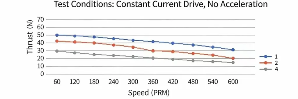
Actual usable thrust must also account for:
- Bearing friction;
- Anti-rotation mechanism friction;
- Guide rail friction;
- Nut preload resistance;
- Seal resistance;
- Extra friction caused by misalignment;
- Inertial force required to accelerate the screw and load;
- Efficiency changes caused by screw and nut wear.
Transmission efficiency η should not be treated as one fixed value.
Trapezoidal screws, ball screws, and planetary roller screws use different friction mechanisms. Their efficiencies are also different. Trapezoidal screw efficiency is strongly affected by lead angle, thread profile, lubrication, and nut material. Ball screws normally have higher efficiency. Preloaded screw systems also require extra friction torque.
The thrust formula is best used for initial estimates and design comparison. Final values should be verified with supplier test curves, allowable axial load, and actual operating conditions.
Required Thrust for Horizontal Loads
For horizontal motion, a lead screw with stepper motor mainly needs thrust to overcome acceleration inertia, guide friction, and external process resistance. It can be estimated as:
F = ma + μmg + Fext
Where:
- m is the moving mass, in kg;
- a is linear acceleration, in m/s²;
- μ is the equivalent friction coefficient of the guide system;
- g is gravitational acceleration, approximately 9.81 m/s²;
- Fext is external process resistance, in N.
For example, the moving mass is 8 kg. Acceleration is 0.4 m/s². The equivalent friction coefficient is 0.02. External resistance is 20 N:
F = 8 × 0.4 + 0.02 × 8 × 9.81 + 20
The result is approximately:
F ≈ 24.8 N
With a safety factor of 1.5, the recommended design thrust is at least:
Fdesign = 24.8 × 1.5 ≈ 37.2 N
The safety factor covers changes in friction, assembly error, lubrication condition, load variation, and motor torque variation.
A higher safety factor may be required for impact loads, frequent starts and stops, or high-reliability equipment.
Do not use a theoretical material friction coefficient without verification.
In real equipment, guide preload, the number of sliders, seal resistance, installation parallelism, and lubrication all affect equivalent friction. When possible, measure both starting thrust and steady running thrust.
Thrust Calculation for Vertical Loads
When a lead screw with stepper motor lifts a load vertically, it must overcome gravity, acceleration force, guide friction, and external resistance. The required thrust can be estimated as:
F = m(g + a) + Ffr + Fext
For example, a 5 kg load is lifted vertically. Even without acceleration and friction, the thrust required to overcome gravity is:
F = 5 × 9.81 ≈ 49.1 N
The required thrust will be higher if fast starting is needed. Guide bushings, seals, springs, air pressure, or other process resistance can also increase the load.
Vertical applications must check both running thrust and the holding method after power loss.
Ball screws have high efficiency and are often easy to back-drive. A small-lead trapezoidal screw should not be assumed to be fully self-locking based only on experience.
Lead screw self-locking depends on:
- Lead angle;
- Friction coefficient of the screw and nut;
- Lubrication condition;
- Nut material;
- Load level;
- Machine vibration;
- Wear of the screw and nut.
Systems involving personnel safety, valuable equipment, or fall protection should use a brake motor, mechanical lock, anti-fall mechanism, or another independent safety device. Do not rely only on screw friction to hold the load.
Why Holding Torque Should Not Be Used Directly to Calculate Thrust
Holding torque is the maximum external torque that an energized stepper motor can resist while stopped.
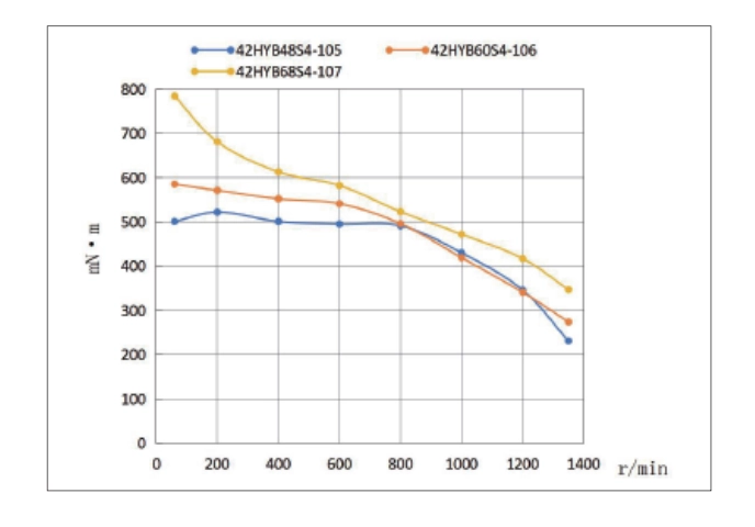
It describes performance at zero speed. It does not represent continuous torque during motion.
As stepper motor speed rises, each commutation period becomes shorter. Coil current may not fully build. Output torque normally decreases.
High-speed stepper motor torque is affected by:
- Drive voltage;
- Phase current;
- Motor inductance;
- Drive method;
- Microstep setting;
- Acceleration time;
- Load inertia;
- Power supply capacity;
- Driver current-limiting method.
Using holding torque directly in the thrust formula usually overestimates actual thrust at high speed.
A machine may run normally during a low-speed test. After speed is increased or acceleration time is reduced, it may lose steps, stall, become noisy, or show position error.
A more reliable calculation process is:
- Calculate motor speed from the target linear speed and screw lead;
- Calculate required thrust from moving mass, acceleration, friction, and external resistance;
- Convert the required thrust into lead screw input torque;
- Check the motor speed-torque curve;
- Confirm the available dynamic torque at the target speed;
- Add a suitable operating safety margin.
Use the following formula to convert thrust back into required torque:
T = FL ÷ (2πη)
The lead L must still be entered in m/rev.
The calculated torque should include extra margin for acceleration inertia, nut preload, bearing resistance, and installation error.
How to Select the Lead
Lead selection for a lead screw with stepper motor is a balance between speed, thrust, resolution, and motor operating speed.
Features of a Small-Lead Screw
A small-lead screw has less linear travel per revolution. It provides higher theoretical thrust at the same torque. It also gives smaller full-step travel. It is suitable for low speed, high resolution, and greater mechanical advantage.
At a high target linear speed, a small lead forces the motor to run faster. Stepper motor torque may drop sharply at high speed.
Features of a Large-Lead Screw
A large-lead screw moves farther per revolution. It provides higher linear speed at the same motor speed. It also reduces the motor speed required to reach the target linear speed.
However, a large-lead screw provides less theoretical thrust. It has larger travel per step. It is also usually easier to back-drive.
Therefore, a small-lead screw does not always provide more actual thrust.
For example, to reach a linear speed of 40 mm/s:
- A 2 mm lead requires 1200 rpm;
- An 8 mm lead requires only 300 rpm.
A 2 mm lead gives greater theoretical mechanical advantage. However, if very little dynamic torque remains at 1200 rpm, its actual thrust may be lower than the 8 mm lead design.
Compare several lead options at the same time. Calculate the required speed, dynamic torque, theoretical thrust, and resolution for each option. Then select the design with the best overall margin.
What Else Should Be Checked After Calculation
Critical Speed
A long and thin lead screw may resonate, whip, and vibrate at high rotational speed.
Critical speed depends on screw root diameter, unsupported length, end support method, and installation accuracy. A thinner and longer screw normally has a lower allowable speed.
Actual operating speed should stay below the supplier limit. A suitable safety margin is also required.
Column Stability
Under axial compression, a lead screw may bend and buckle like a slender column.
The allowable compressive load must be checked, especially when a long-stroke, small-diameter screw pushes a load outward. Enough calculated thrust does not mean the screw structure is safe.
Once the screw bends, friction rises quickly. Severe bending can damage the nut, bearings, and motor.
Radial Load and Guidance
A lead screw is mainly designed for axial load. It should not replace a linear guide.
Radial force, side force, and overturning moment from the load should be carried by guide rails, guide bushings, or sliders.
Continuous side loading increases friction, wear, and operating noise. It also reduces positioning stability. In severe cases, the screw may bend or the nut may jam.
Duty Cycle and Temperature Rise
A trapezoidal screw uses sliding friction. High load, high speed, and long continuous operation can cause significant temperature rise.
Do not check only peak thrust during selection. Also confirm:
- Run time per cycle;
- Cooling time while stopped;
- Number of reciprocating cycles per minute;
- Ambient temperature;
- Allowable nut temperature;
- Motor winding temperature rise;
- Operating temperature of the grease.
At the same thrust, intermittent operation and continuous operation can require very different screw, nut, and motor specifications.
Lubrication and Operating Environment
Different screw and nut materials have different lubrication requirements.
Medical, cleanroom, vacuum, high-temperature, low-temperature, dusty, or food-contact environments may require special grease, nut materials, seals, and surface treatments.
Changes in lubrication also change screw efficiency, friction, noise, and self-locking performance. Do not continue using the original efficiency data after changing the grease without validation.
Axial Clearance and Service Life
Anti-backlash or preload structures improve reversing accuracy. However, they also increase friction and wear.
Preload should balance positioning requirements, operating efficiency, temperature rise, and service life.
Machines that move in only one direction may not need extremely small clearance. Machines with frequent bidirectional positioning should focus on backlash control and nut wear.
Conclusion
The core calculations for a lead screw with stepper motor can be summarized as follows:
Linear speed = motor speed × lead ÷ 60
Travel per step = lead ÷ full steps per revolution
Theoretical thrust = 2π × efficiency × dynamic torque ÷ lead
Reliable selection does not depend on one formula. It depends on the complete calculation sequence.
First define the load, speed, acceleration, stroke, installation direction, and duty cycle. Then select the screw type and lead. Calculate the required speed and thrust. Verify them with the dynamic torque at the target speed.
Finally, check critical speed, column stability, back-driving, axial clearance, guidance, lubrication, temperature rise, and service life.
Treat the motor, screw, nut, bearings, guides, and load as one complete system. This avoids a common problem: the theoretical data looks sufficient, but the machine loses steps or jams. A system-level check helps you select the right lead screw with stepper motor solution.