Stepper motors are a type of actuator that can accurately convert electrical pulse signals into fixed angular displacements, occupying a core position in automated control systems. According to different structures and driving methods, stepper motors are mainly divided into three categories: Variable Reluctance (VR), Permanent Magnet (PM), and Hybrid (HB).
According to data from Cognitive Market Research, the global permanent magnet stepper motor market size will reach 3775.91 million US dollars in 2025 and is projected to grow to 6063.79 million US dollars by 2033, with a Compound Annual Growth Rate (CAGR) of 6.1%.
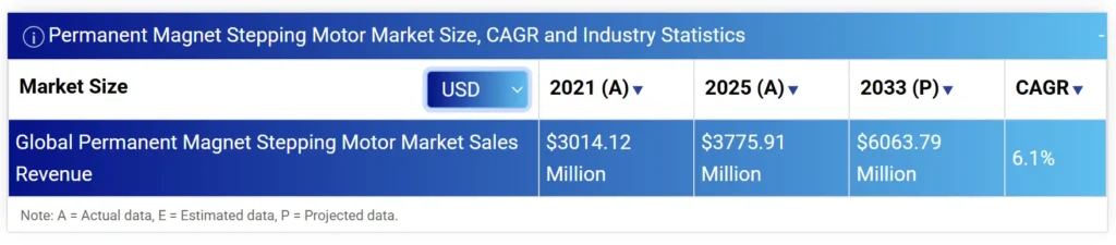
This growth trend reflects the sustained demand for permanent magnet stepper motors in consumer electronics, smart devices, medical instruments and other fields.
This paper systematically analyzes the core definition, working principle, typical applications and key advantages of permanent magnet stepper motors, and further discusses their inherent limitations. On this basis, it focuses on improvement schemes represented by gearbox reduction and lead screw slide linear transmission, helping engineers achieve higher performance and reliability in practical projects.
Key Takeaways
- Permanent magnet stepper motors convert electrical pulses into precise angular displacement using the interaction between a permanent magnet rotor and an electromagnetic stator.
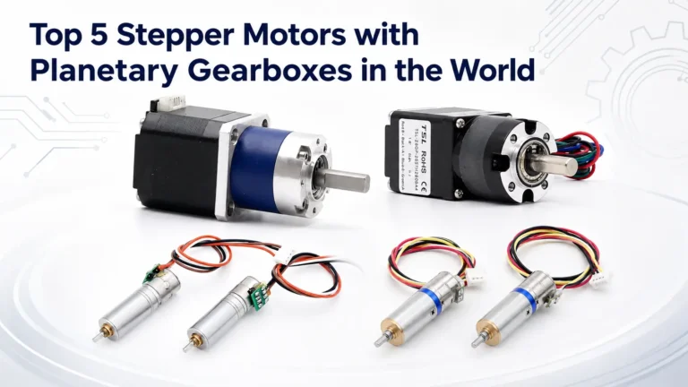
- The BYJ series motor integrates a multi-stage reduction gearbox to achieve high torque output and ultra-fine step angles within a compact volume.
- Open-loop control systems enable accurate positioning without the need for costly encoders, making them a cost-effective solution for mass-produced automation.
- Gear reduction solutions not only enhance angular resolution but also act as a mechanical damper to absorb vibrations and improve motion smoothness.
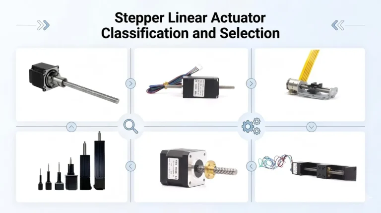
- Lead screw and slider systems effectively transform rotary motion into linear progression, overcoming the motor’s native limitation in direct linear feed.
- Closed-loop control upgrades utilize magnetic encoders to eliminate the risk of “lost steps” under high-load conditions, ensuring absolute positioning reliability.
- Advanced magnetic materials allow modern PM motors to maintain stable signal integrity and mechanical performance even in extreme environments as low as -55°C.
Permanent Magnet Stepper Motors : Definition and Structural
A permanent magnet stepper motor is a type of synchronous motor. Its rotor is made of permanent magnetic materials with multiple pairs of magnetic poles, typically ferrite or rare-earth alloys.
It uses permanent magnets as the source of the rotor magnetic field. Through sequential excitation of the multi-phase stator windings, the rotor is driven to rotate synchronously in a fixed step angle.
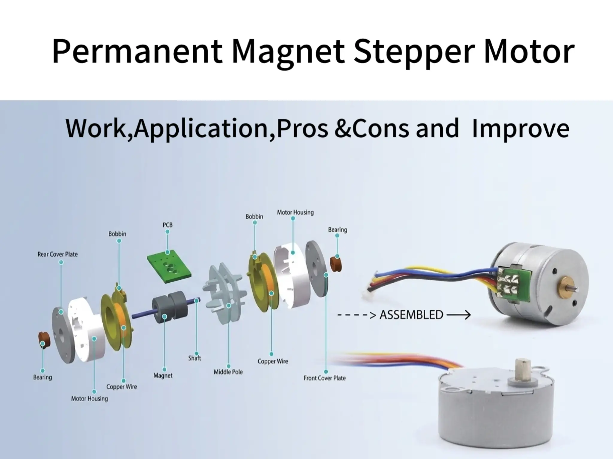
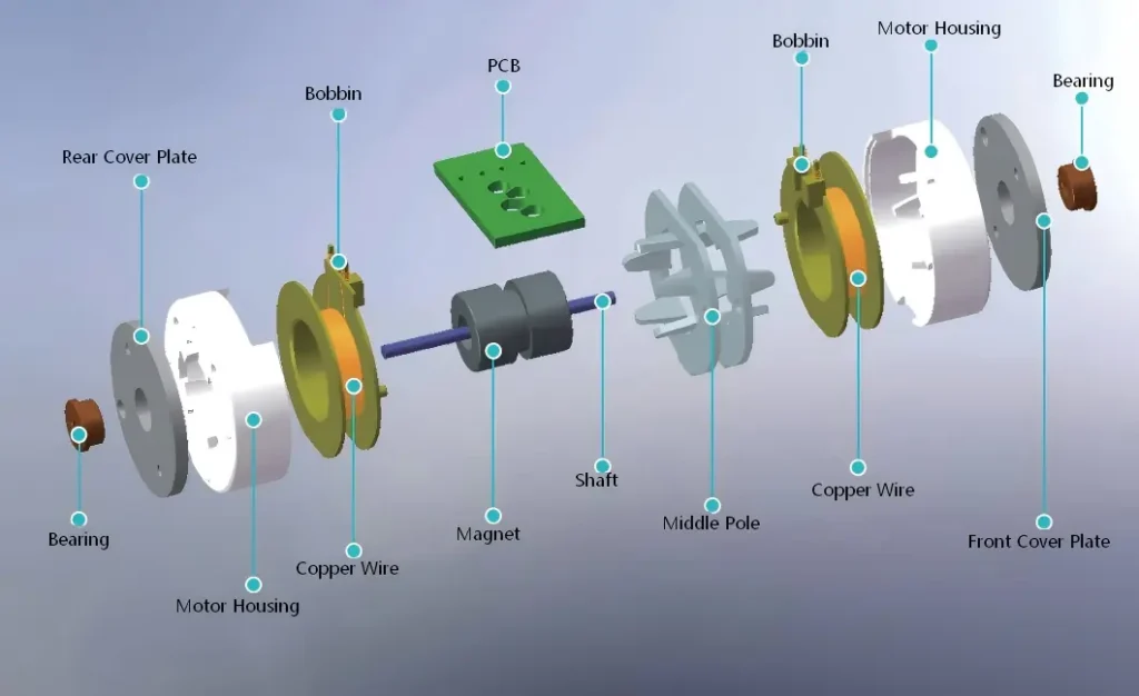
Its core structure consists of a stator and a rotor, as shown in Figure 2 below.
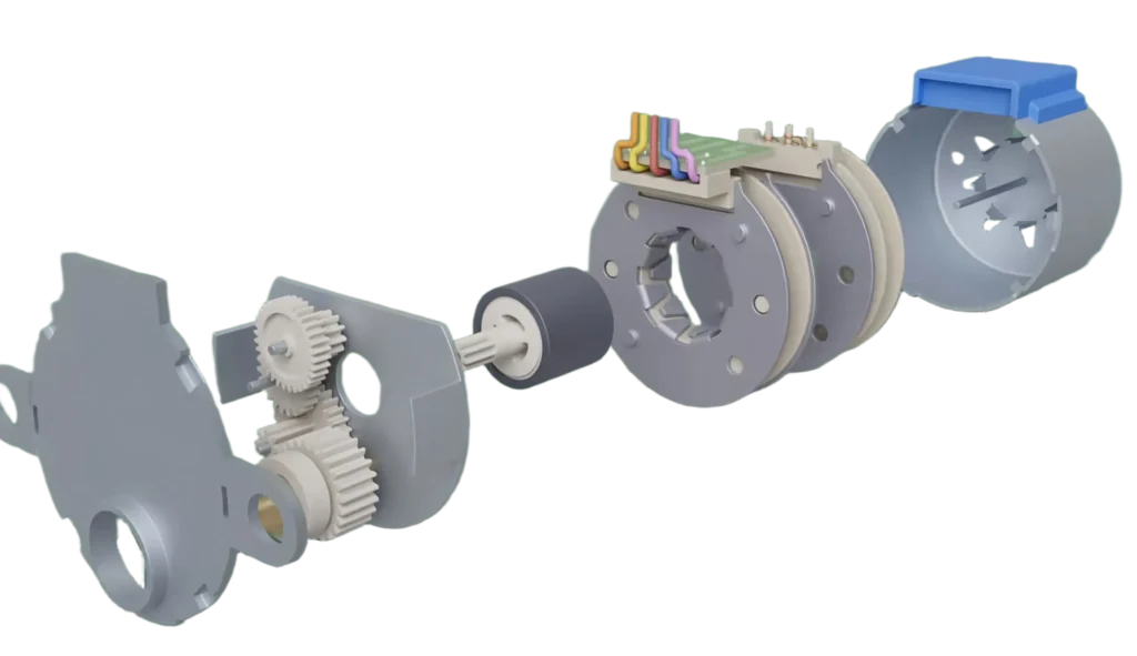
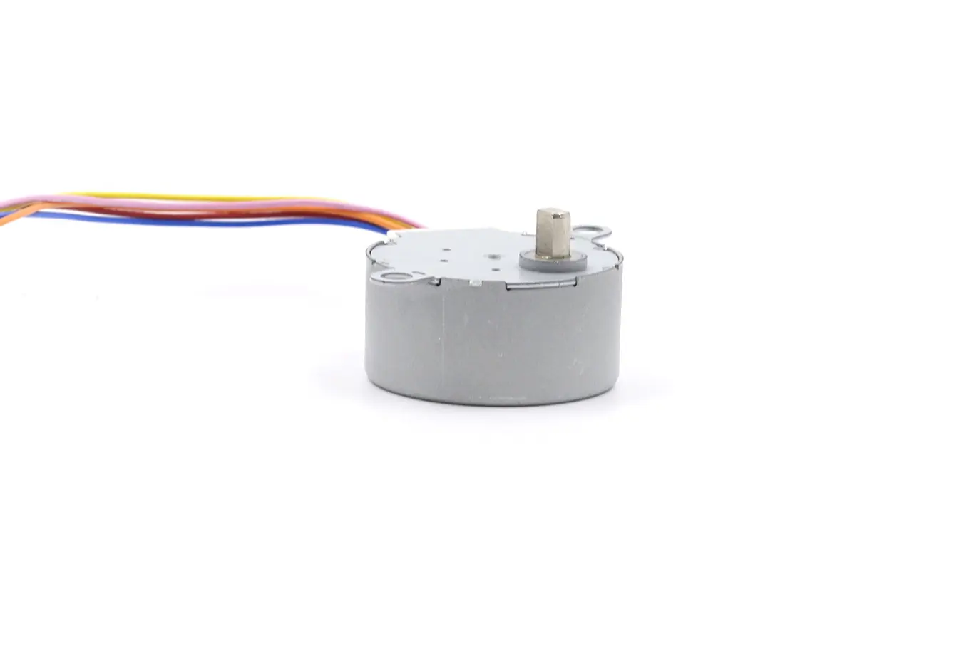
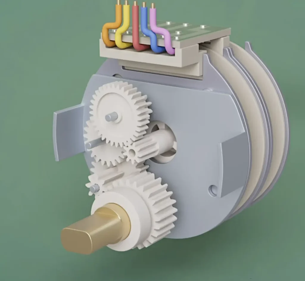
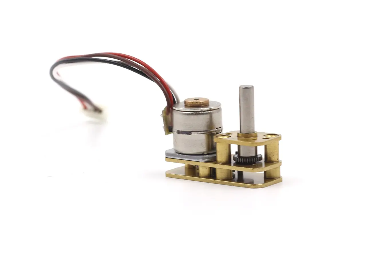
The BYJ series motors commonly used in daily applications are the most representative permanent magnet geared stepper motors in the industry.
They integrate a permanent magnet stepper motor with a multi-stage reduction gearbox into a single compact structure, making them the most widely used type of permanent magnet stepper motor in consumer applications.
Figure 3 shows an exploded view of the TSL-28BYJ-35 motor.
How a Permanent Magnet Stepper Motor Works
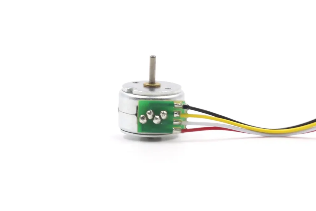
The BYJ series is a common type of permanent magnet stepper motor, often used in valve applications. It typically has 5 lead wires, whereas a conventional two-phase permanent magnet stepper motor usually has 4 wires. So what are the differences in their working principles?

BYJ Series Permanent Magnet Stepper Motor
To better understand this, we first look at a simplified model in Figure 4. When energized once in sequence (A2 → A1 → B1 → B2), a 4-coil motor achieves a 45° rotation, meaning a 45° step angle.
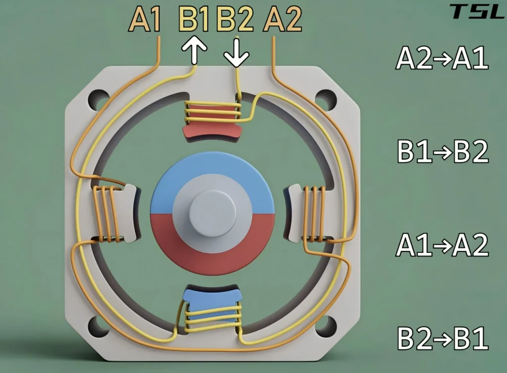
For the permanent magnet stepper portion of the TSL-28BYJ48 motor, the step angle is 5.625°. Does this mean the stator must have a significantly increased number of windings? In fact, the motor uses only two sets of coils (as shown in Figure 2).
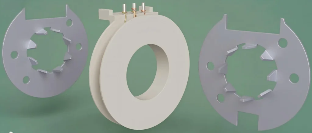
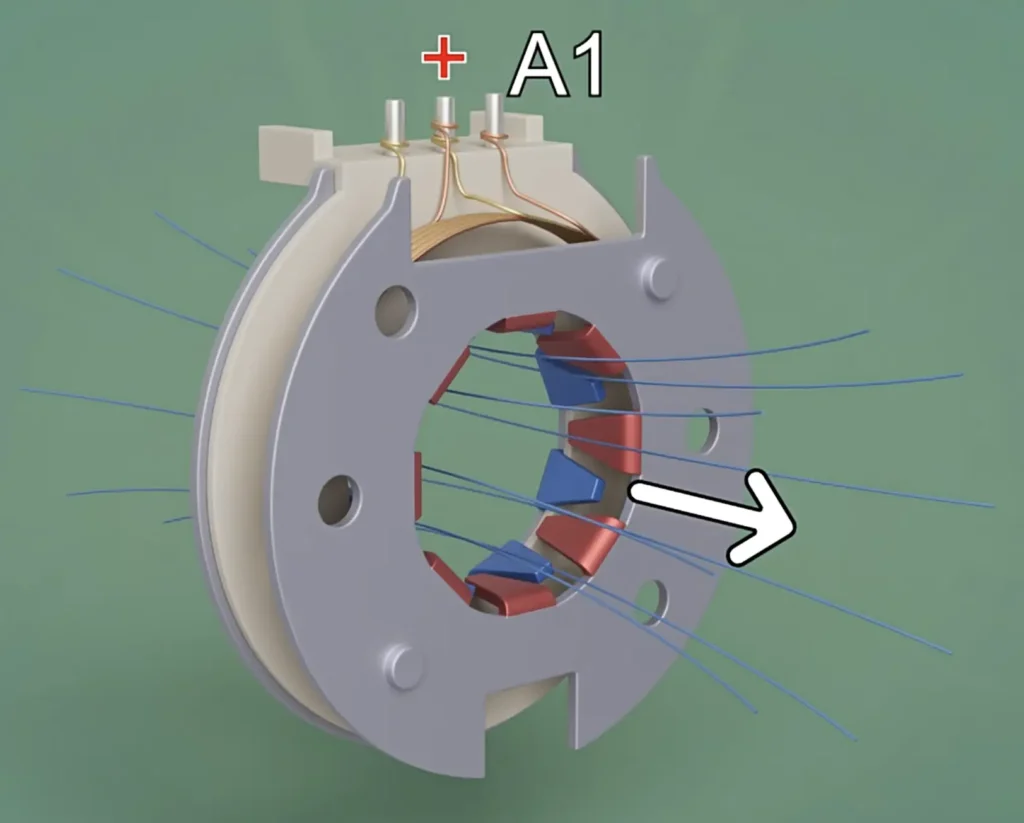
In this type of permanent magnet stepper motor, the stator adopts a more subtle design. First, consider coil set A (Figure 5), where the coil is sandwiched between two eight-pole magnetic conductive plates.
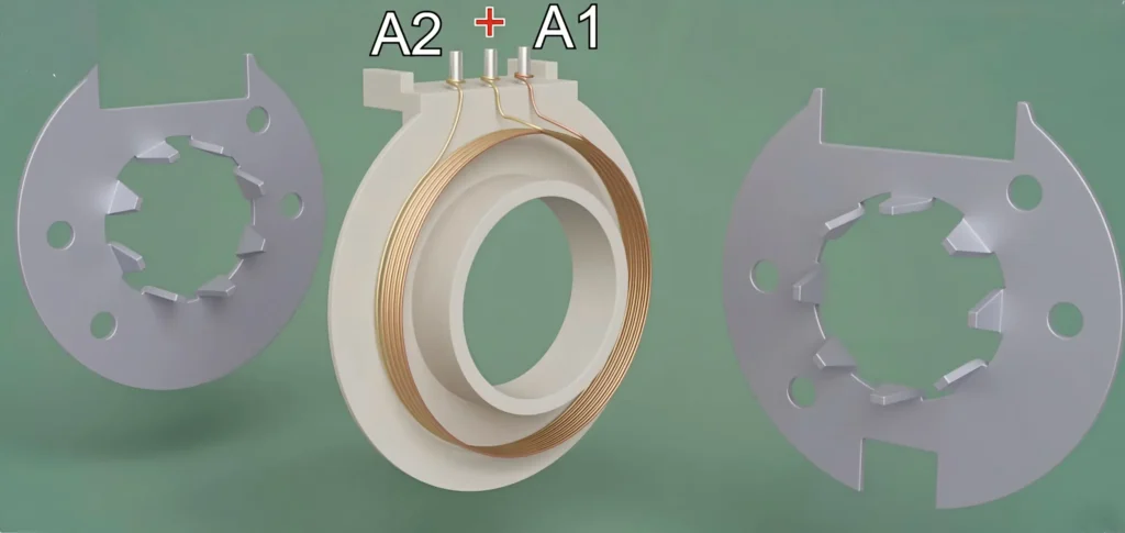
This coil set consists of two windings, A1 and A2, which share a common positive terminal (Figure 6).
When coil A1 is energized, it generates a forward magnetic field, as shown in Figure 7.
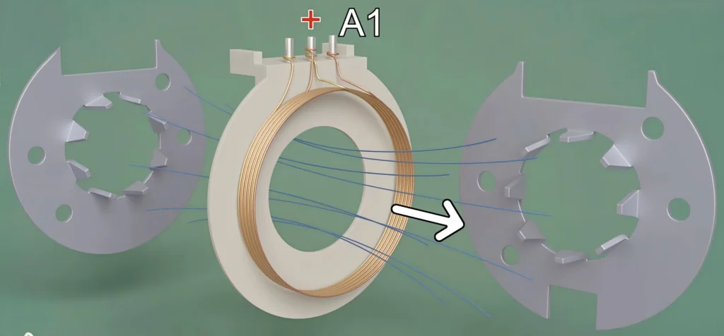
The rear magnetic conductive plate near the coil behaves as an N pole, while the front plate behaves as an S pole (Figure 8).
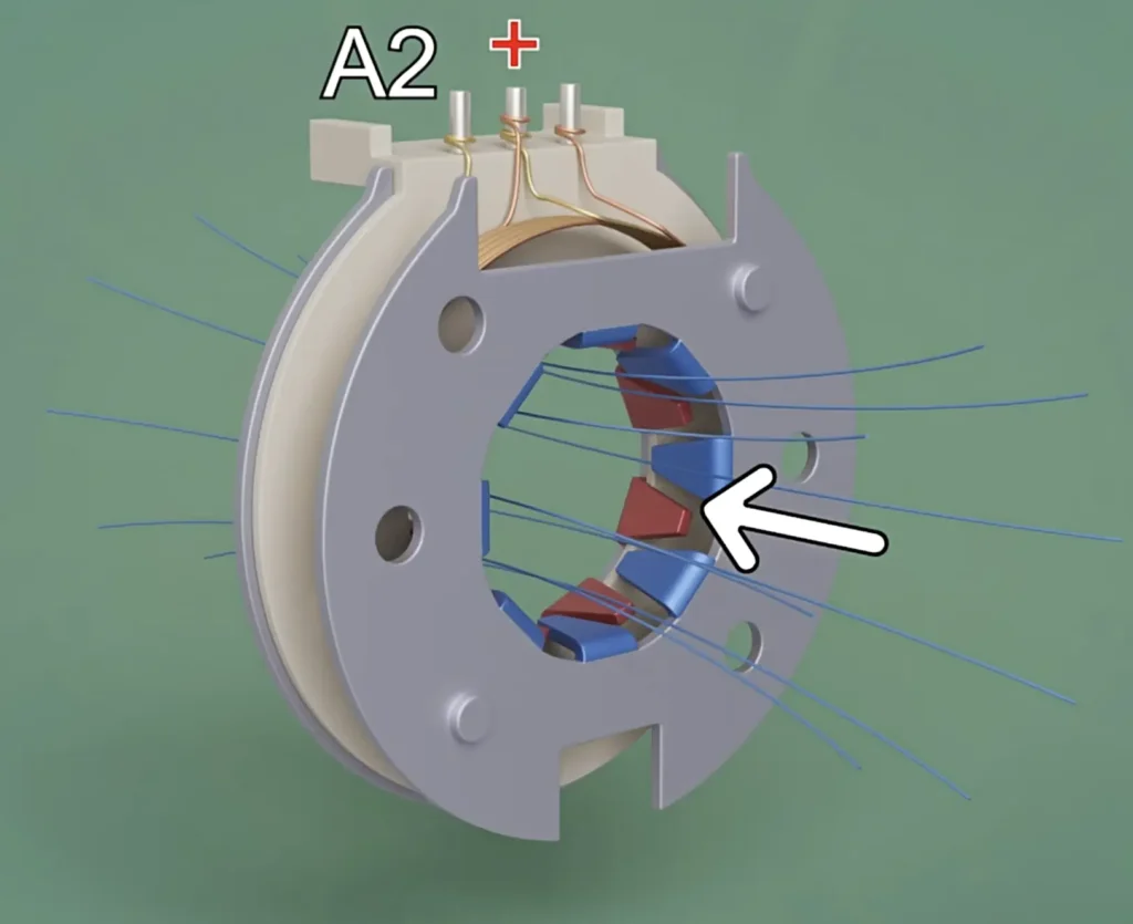
When A2 is energized, the direction of the magnetic field is exactly reversed, and the magnetic poles of the magnetic claws change accordingly, as shown in Figure 9.
The other coil set, B, is wound in the same way as A. The two coils are then combined and share a common positive power supply terminal, as shown in Figure 10.
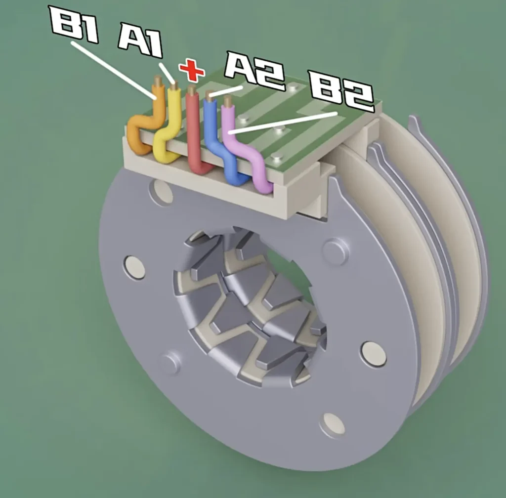
After the two coils are combined, the magnetic claw sections of the magnetic conductive plates are spaced 11.25° apart in pairs, as shown in Figure 10.
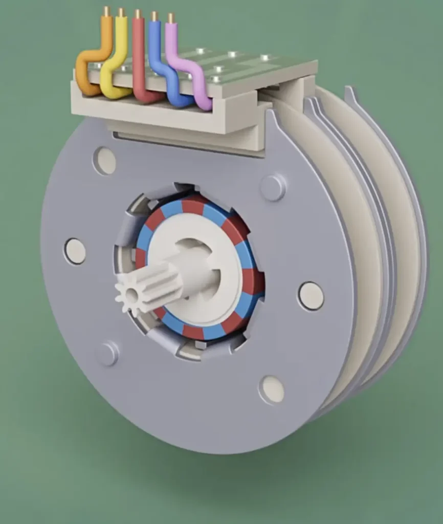
The rotor section then uses permanent magnets with 8 pairs of N/S poles, as shown in Figure 11. This forms the permanent-magnet stepper motor section with a step angle of 5.625°. The TSL-28BYJ-35 motor further uses gear reduction to increase torque, allowing an even smaller step angle, as shown in Figure 12.
Common Two-Phase Permanent-Magnet Stepper Motor
In fact, its operating principle is the same as that of the BYJ series permanent-magnet stepper motor. The main difference lies in the circuit schematic: the number of lead wires is reduced because there is no shared positive power supply wire. For the circuit schematic, please refer to Figure 12 below.
Step Angle Calculation
The basic step angle of a permanent-magnet stepper motor is determined by the number of stator phases and the number of rotor magnetic pole pairs. The calculation formula is:
Where:
- θs is the basic step angle;
- m is the number of stator winding phases;
- p is the number of rotor permanent-magnet pole pairs.
For common two-phase permanent-magnet stepper motors, the basic step angle is usually 7.5° or 15°. By contrast, BYJ series motors use multi-stage gear reduction, which can reduce the output shaft step angle to 0.088° or even lower, greatly improving angular resolution.
Unlike servo motors, permanent-magnet stepper motors can achieve accurate positioning in open-loop control mode. Without adding extra position feedback components, the rotation angle can be precisely controlled by the number of input pulses, significantly simplifying the complexity and cost of the control system.
Unique Competitive Advantages of Permanent-Magnet Stepper Motors
Compared with variable-reluctance and hybrid stepper motors, permanent-magnet stepper motors offer irreplaceable differentiated advantages. These advantages are also the core reasons why they have been widely adopted on a large scale.
Excellent Cost-Effectiveness and Reliability
Among various motor types, permanent-magnet stepper motors have one of the simplest physical structures. They do not require complex rotor windings or commutators, resulting in very few mechanical failure points. The main wear typically occurs only at the bearings.
Because they can be manufactured using high-volume stamping processes, their unit cost is usually only a fraction of that of hybrid stepper motors. This makes them especially suitable for cost-sensitive consumer electronic products.
Accurate Open-Loop Control
PM motors naturally provide position-holding characteristics. As long as the load torque does not exceed the motor’s pull-in torque, the output displacement of the motor is completely determined by the number of input pulses, with no accumulated error.
This means designers can eliminate expensive encoders and complex closed-loop control algorithms, greatly simplifying the system architecture while improving overall reliability.
Quiet Low-Frequency Operation
Compared with variable-reluctance stepper motors, permanent-magnet stepper motors have smaller torque ripple and significantly reduced resonance during low-frequency operation. As a result, they generate less operating noise and are particularly suitable for home appliances, office equipment, and other applications requiring quiet operation.
Compact Design Adaptability
By integrating reduction gearboxes or lead-screw modules, permanent-magnet stepper motors can deliver high torque and high-precision output within a very limited installation space. This makes them an ideal fit for consumer electronics, automotive electronics, and other applications with strict space constraints.
Core Inherent Limitations of Permanent-Magnet Stepper Motors
Large Basic Step Angle, Low Angular Resolution and Positioning Accuracy
For conventional permanent-magnet stepper motors without a reduction mechanism, the basic step angle is typically 7.5° or 15°, which is much larger than the 1.8° step angle of hybrid stepper motors.
As a result, their single-step positioning accuracy is relatively poor, and their angular resolution is insufficient for high-precision positioning applications.
Limited Output Torque and Poor High-Speed Performance
The permanent-magnet rotor has relatively high rotational inertia. During high-speed operation, the back electromotive force rises rapidly, causing the output torque to drop sharply as speed increases. Therefore, permanent-magnet stepper motors are mainly suitable for low-speed, light-load applications and are not ideal for high-speed or high-torque operating conditions.
Susceptibility to Step Loss in Open-Loop Control and Weak Overload Capability
Under conventional open-loop control, there is no position feedback mechanism. When the load exceeds the motor’s maximum holding torque, step loss may occur, resulting in positioning errors that cannot be corrected in real time.
Inability to Directly Achieve Precision Linear Transmission
The motor itself can only output rotary angular displacement. However, many automation applications require linear positioning. The native structure of a permanent-magnet stepper motor cannot directly meet such requirements without additional transmission mechanisms.
How to Improve Permanent Magnet Stepper Motors
Although permanent-magnet stepper motors offer outstanding advantages, they also face several significant “pain points” in high-performance motion control applications. To address these limitations, the engineering industry has developed several mature improvement solutions.
Improving Resolution: Adding a Gear Reduction System
Traditional PM stepper motors commonly have a step angle of 7.5°, which means there are only 48 effective positions per revolution. This is far from sufficient for precision positioning applications, such as camera pan-tilt platforms. To overcome this limitation, conventional BYJ series motors, such as the widely used 28BYJ-36, optimize performance by integrating gear sets or gearboxes.
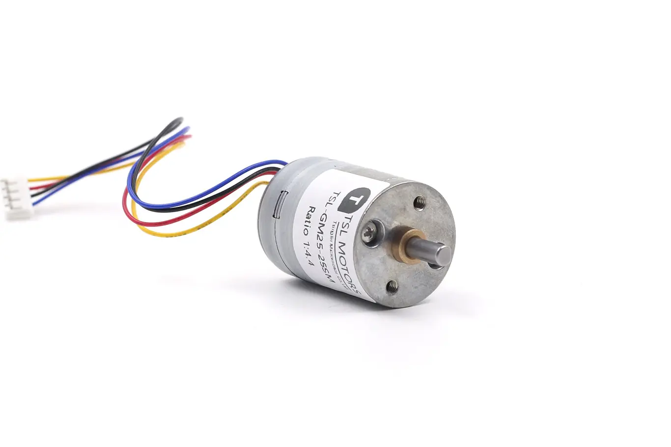
Taking the 28BYJ-36 as a typical example, its internal core is a 4-phase, 5-wire permanent-magnet stepper motor, while an external multi-stage gear reducer with a commonly used reduction ratio of approximately 1:64 is integrated. This brings the following benefits:
Ultra-High Resolution
The original step angle is approximately 5.625°. After 1:64 reduction, the effective step angle of the output shaft becomes:5.625∘/64≈0.088∘
In half-step drive mode, the output shaft requires an impressive 4096 pulses to complete one full revolution.
Torque Multiplication
According to mechanical principles, the output torque is proportional to the reduction ratio, ignoring friction losses. This means that a compact PM motor, amplified by a gearbox, can generate enough driving force to operate small valves, robotic arm joints, or heavy curtains.
Damping and Stability
The friction and inertia between gears act as a natural low-pass filter, greatly absorbing the vibration generated by the stepper motor itself. As a result, the final mechanical output becomes smoother and quieter.
Improving Positioning Accuracy: Lead Screw and Slide Table Systems
For applications that require linear motion, such as left-to-right or up-and-down movement, a rotary stepper motor must use a conversion mechanism. Lead screws and slider/slide table systems are industry-standard solutions for achieving this conversion.
A lead screw is a mechanical device that converts rotary motion into linear motion. The motor output shaft functions as a screw, which passes through a fixed nut. When the screw rotates, the nut moves linearly along the axis.
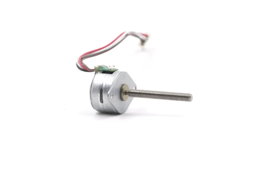
For example, if a PM motor with 24 steps per revolution drives a lead screw with a 2 mm lead, the linear accuracy per step can reach:2 mm/24≈0.083 mm
For a slide table system, the nut matched with the lead screw is rigidly connected to the linear slide table, and the slide table moves along high-precision guide rails.
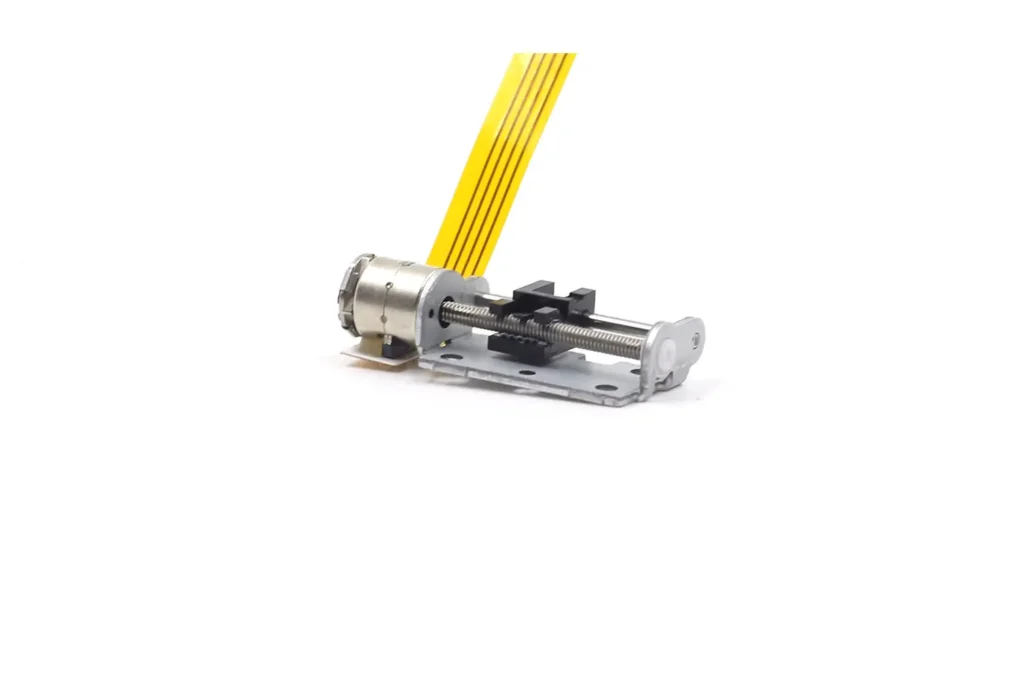
Each input pulse causes the motor to rotate by a fixed step angle, driving the lead screw to rotate synchronously. The lead screw nut then moves the slide table by a fixed linear distance.
Closed-Loop Control
By adding a magnetic encoder or optical encoder to the motor shaft, a closed-loop position control system can be established. The encoder provides real-time feedback on the actual rotor position. When step loss or positioning deviation occurs, the control system can correct the error in real time.
This completely solves the step-loss problem associated with open-loop control, while significantly improving overload capability and high-speed operating performance.
Permanent Magnet Stepper Motors Applications
With their compact structure, controllable cost, quiet operation, and self-locking performance, permanent magnet stepper motors are widely used in many fields. These include consumer electronics, smart home devices, industrial instruments, automotive electronics, and other applications.
Smart Home and Consumer Electronics
The BYJ series is widely used in smart home and consumer electronics. Typical applications include air-swing mechanisms in air conditioners and refrigerators. They are also used in lid-opening and flushing valve drives for smart toilets.
Other applications include clutch actuators in smart door locks, pan-tilt rotation for security cameras, lens focusing and keystone correction in home projectors, side-brush and airflow control in robotic vacuum cleaners, and mist-volume adjustment in humidifiers.
Office Automation Equipment
Applications include paper feeding and print-head positioning in printers. They are also used for scanner head linear drive, drum positioning and paper conveying in copiers, and document feeding mechanisms in fax machines.
Precision Instruments and Medical Equipment
Permanent magnet stepper motors are used in laboratory micro-injection pumps for precise dosing. They are also used for air-valve flow control in ventilators, stage lifting and filter switching in optical microscopes, optical path adjustment in spectrophotometers, and valve actuation in industrial flowmeters.
Automotive Electronics
Typical applications include headlight beam-angle adjustment and air-direction control in automotive air-conditioning systems. They are also used for screen flipping and angle adjustment in in-vehicle entertainment systems, as well as valve-control systems for battery thermal management in new energy vehicles.
Small Automation Equipment
Applications include extruder and feed-axis drives in desktop 3D printers. They are also used for precision feeding in small CNC engraving machines, station switching in automated inspection equipment, and precision positioning in linear slide modules.
Conclusion
Permanent magnet stepper motors have a simple structure, controllable cost, power-off self-locking capability, and quiet operation. Because of these advantages, they hold an irreplaceable position in consumer electronics, smart home devices, precision instruments, and other fields. Among them, BYJ series permanent-magnet geared stepper motors have become benchmark products in civil automation applications.
Permanent magnet stepper motors also have inherent limitations. These include large native step angles, insufficient torque, and the inability to directly achieve linear transmission. To solve these problems, the industry has adopted several engineering solutions. These include integrated reduction gearboxes, lead-screw slide table modules, and closed-loop control upgrades. These solutions greatly improve positioning accuracy, output torque, and application flexibility.
In the future, permanent magnet materials, drive technology, and precision transmission technology will continue to improve. Permanent-magnet stepper motors will move toward higher precision, lower power consumption, smaller size, and greater integration. They will continue to play an important role in more precision automation applications.
FAQ
Q1: Why does my 28BYJ-36 motor lose torque and emit a high-pitched noise at high speeds?
A: This is due to the large rotor inertia of PM motors and the rapid rise of back EMF at high speeds, which prevents the drive current from reaching its target. PM motors are optimized for low-speed operation (typically below 300-600 rpm). For higher speeds, you should reduce the load or increase the driving voltage.
Q2: How does “Backlash” in the gearbox affect the precision of a reduction PM stepper motor?
A: Backlash is the physical gap between gears that causes a delay in output movement when reversing direction. While negligible for unidirectional loads like AC louvers, it can cause positioning errors in bidirectional applications like security cameras. This can be mitigated through software compensation or by using high-precision gearboxes.
Q3: Can a PM stepper motor maintain its position when power is cut off?
A: Yes, to an extent. Unlike VR motors, PM motors have “Detent Torque” caused by the permanent magnets even when unpowered. For a stronger hold, applying a constant holding current while powered will lock the rotor in place, though this generates heat.
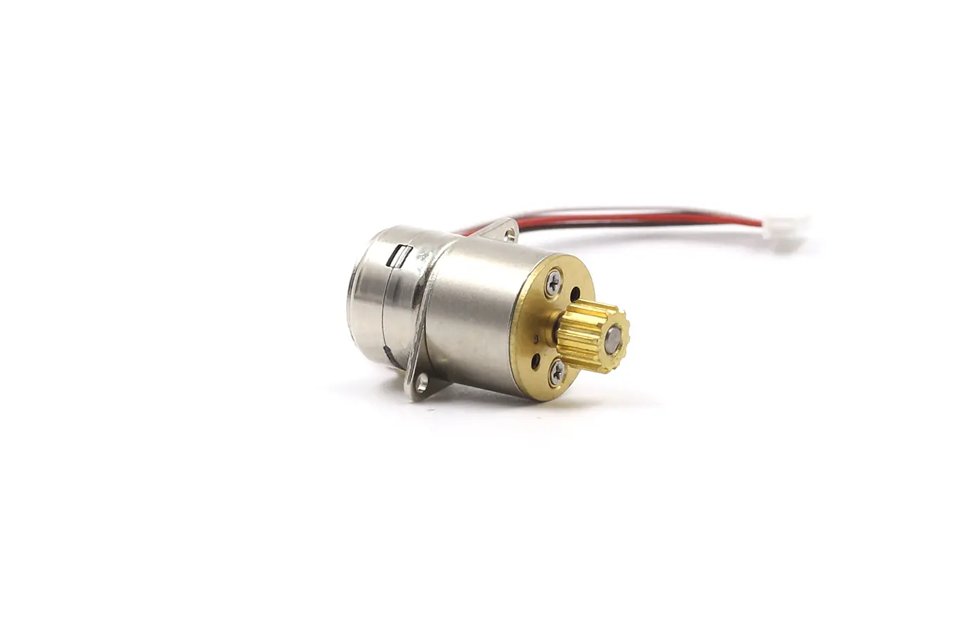
Micro Stepper Motor
TSL Motor’s Micro Stepper Motors are based on PM stepper motor technology.In this category, “micro stepper motor” refers specifically to PM stepper motors.Diameters range from 6 mm to 42 mm.Compact size.Stable performance.
TSL has focused on micro stepper motors for many years.We offer strong customization capabilities.Output shaft customization is available.Mounting structures can also be customized.Including double shaft and through-shaft designs.If you cannot find a suitable model, please contact us.Our mature platform supports efficient custom development.Ideal for camera iris actuators, optical modules, and precision positioning applications.