Hybrid stepping motor combines permanent magnet (PM) and variable reluctance (VR) structures. This unique design balances precision, torque density, and cost control effectively.
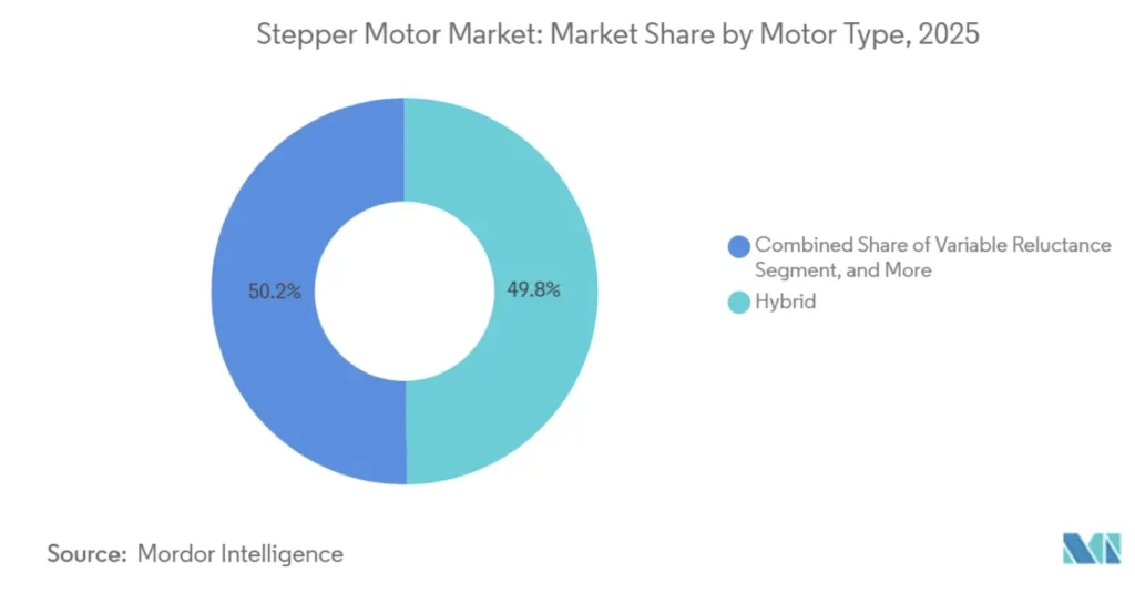
In 2025, they held the largest share of the global market at 49.78%. They are especially popular in the NEMA 23 size. These motors deliver a holding torque exceeding 2 N·m.
Demand is growing for reliable positioning in industrial automation, semiconductor equipment, medical instruments, and desktop manufacturing. Consequently, they have become the mainstream actuators for medium-low speed, high-precision applications.
This article systematically explains their working principle, structural characteristics, and step angle calculation. It also compares them with similar motors and lists typical applications. This helps readers build a complete cognitive framework from fundamentals to selection.
Key Takeaways
- The Hybrid Stepper Motor achieves an ideal balance of high torque and precision by merging Permanent Magnet and Variable Reluctance technologies.
- The multi-toothed rotor design allows these motors to achieve standard 1.8° or 0.9° step angles without requiring complex external gearing.
- NEMA standards regulate the flange mounting dimensions, ensuring global interchangeability across industrial automation hardware.
- Microstepping technology effectively resolves the inherent vibration and resonance issues typically found in low-speed stepper operations.
- Hybrid motors deliver full rated torque at startup, making them superior for applications requiring frequent, high-precision starts and stops.
- Closed-loop control systems eliminate the risk of “lost steps” by integrating encoder feedback for real-time position correction.
- Integrated stepper motors—combining the motor, driver, and controller—are becoming the preferred actuators for compact, interference-resistant smart manufacturing.
Hybrid Stepper Motor Definition and Structure
A hybrid stepper motor is named “hybrid” because it ingeniously integrates the advantages of both permanent magnet (PM) stepper motors and Variable Reluctance (VR) stepper motors.
It adopts the permanent magnet from PM stepper motors. This is an axially magnetized permanent magnet inserted at the rotor center. It incorporates the toothed structure from VR stepper motors. This includes ferromagnetic cores (rotor cups) with fine slots at both ends of the rotor.
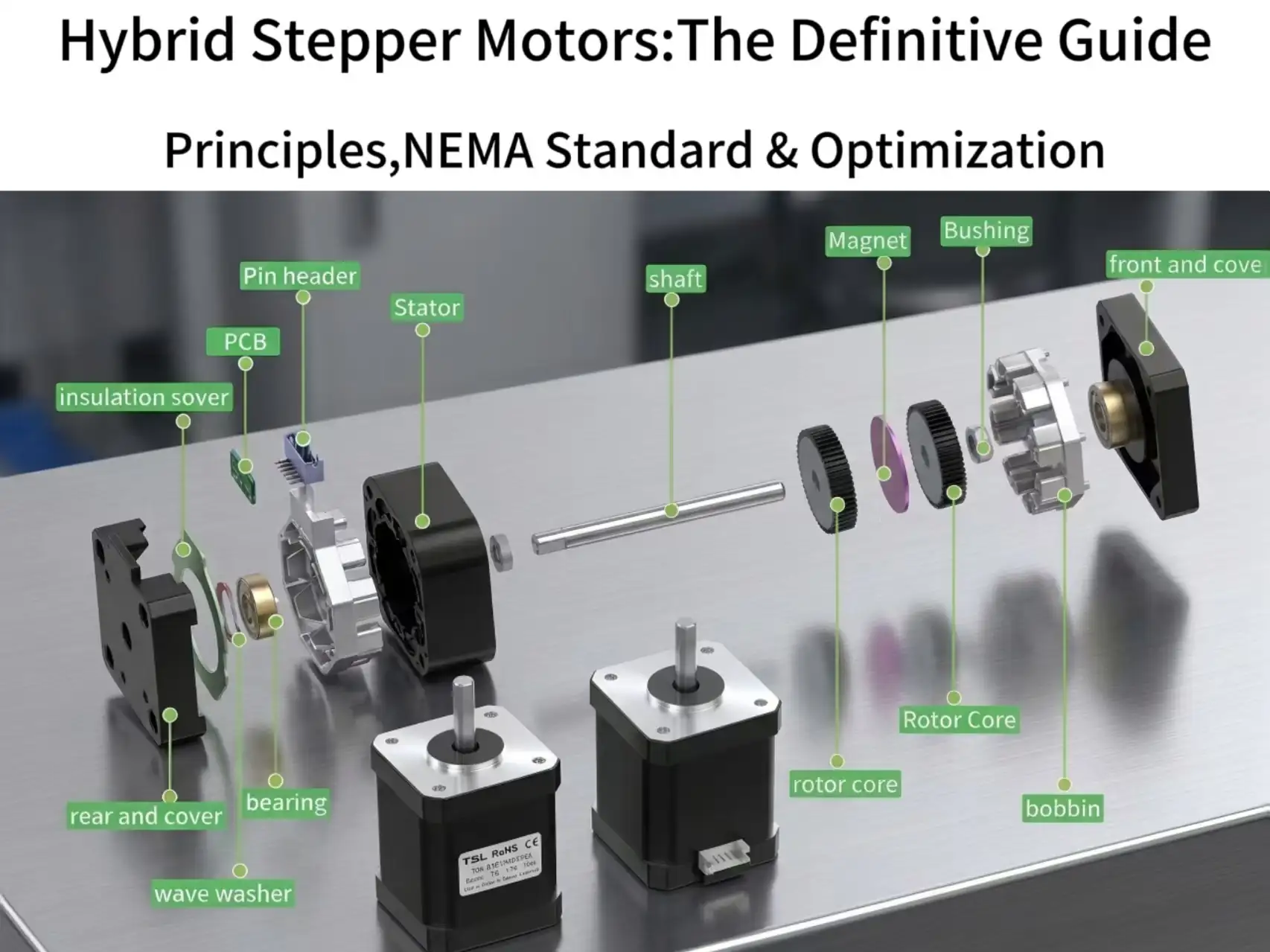
The core of a hybrid stepper motor consists of a stator and a rotor.
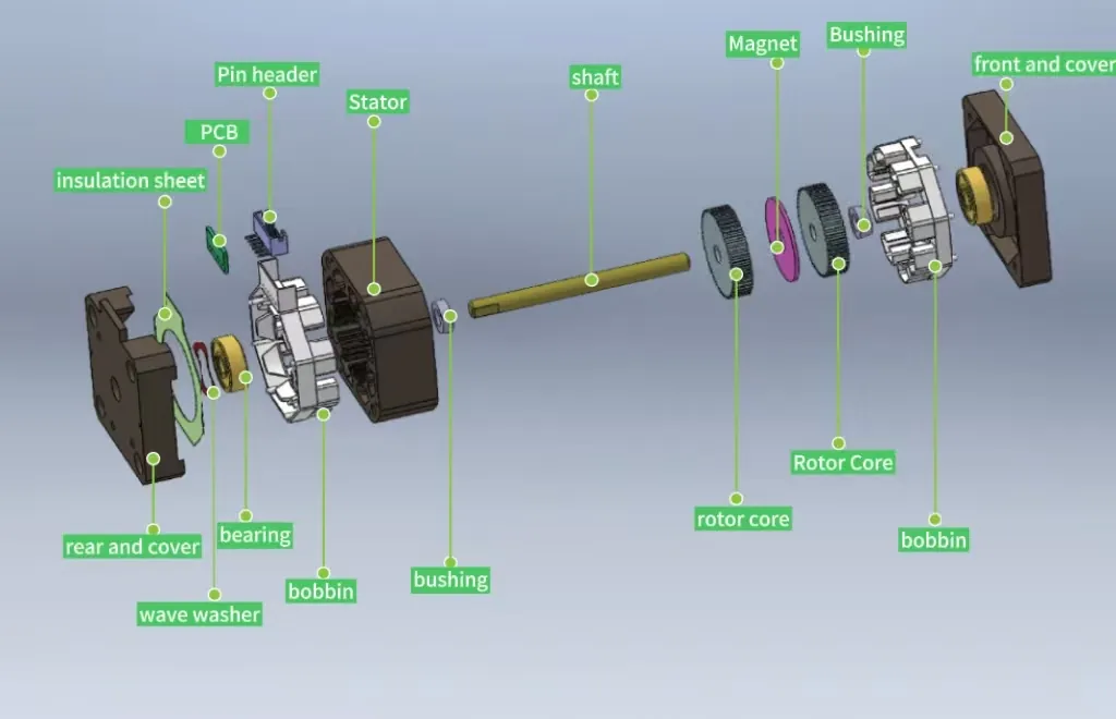
The stator is typically made of laminated silicon steel sheets with multiple poles. Each pole bears uniformly distributed small teeth. Excitation windings are wound around the stator poles. These are usually in 2-phase or 3-phase configurations.
The rotor represents the essence of the hybrid design. Two cylindrical gear-shaped cores (rotor cups) are mounted on the rotor shaft. An axially magnetized cylindrical permanent magnet is sandwiched between them.
This means one end of the permanent magnet magnetizes the front core as the North (N) pole. The other end magnetizes the rear core as the South (S) pole. For minimal step increments, the teeth of the front and rear cores are precisely offset by half a tooth pitch (detailed in Chapter 3).
Hybrid Stepper Motor Working Principle
Hybrid stepper motors operate based on the physical law of “like poles repel, opposite poles attract” and the minimum reluctance characteristic of reluctance motors. When a driver supplies current to the stator windings, the stator generates a magnetic field. This field interacts with the constant magnetic field produced by the rotor permanent magnet.
The rotor tends to move to a position where stator teeth and rotor teeth align. This minimizes magnetic reluctance and maximizes magnetic flux density in the magnetic circuit. Since the teeth of the front and rear rotor cups are offset, a specific alignment occurs. When phase A is energized to align the front N-pole teeth, the rear S-pole teeth remain misaligned with the stator teeth.
When current switches to phase B, the stator magnetic field rotates. The magnetic circuit seeks the path of least resistance. Driven by this tendency, the rotor is forced to rotate by an extremely small angle. This angle is one step angle, typically 1.8°. This movement aligns the next set of teeth.
How Hybrid Stepper Motors Achieve 1.8° / Smaller Step Angles
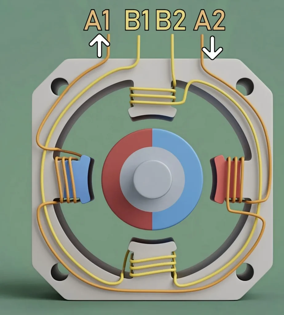
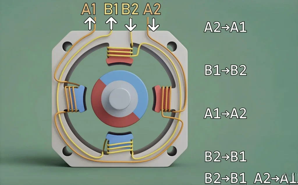
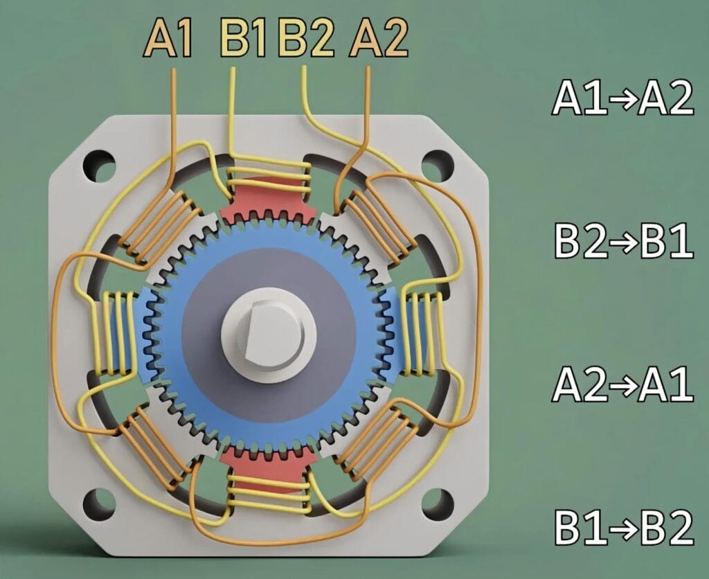
For easier understanding, refer to the simplified model in Figure 2. Following the energization sequence in Figure 2, the rotor clearly rotates 90° per pulse—far too coarse for most applications.
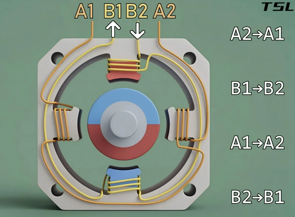
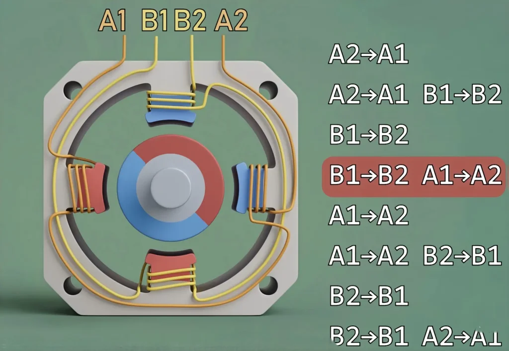
As shown in Figure 3, simultaneous energization of B2→B1 and A2→A1 subjects the rotor to two magnetic fields. This rotates it by 45°.
Combining the energization sequences of Figure 2 and Figure 3 (as in Figure 4) enables 45° per step control. This is the basic 2-phase stepper motor, with 45° as its step angle.
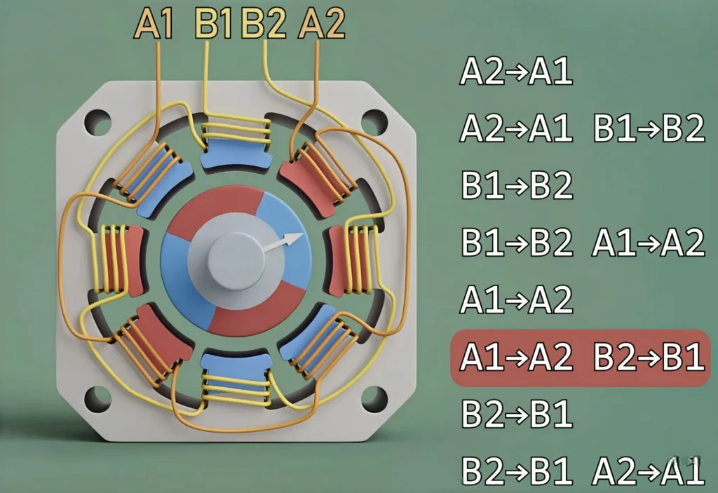
Doubling the windings (still wound with two wires, as in Figure 5) and following the same sequence yields a 2-phase hybrid stepper motor with a 22.5° step angle.
Does achieving a 1.8° step angle require exponentially more windings? The answer is no. Hybrid stepper motors use a more sophisticated design.
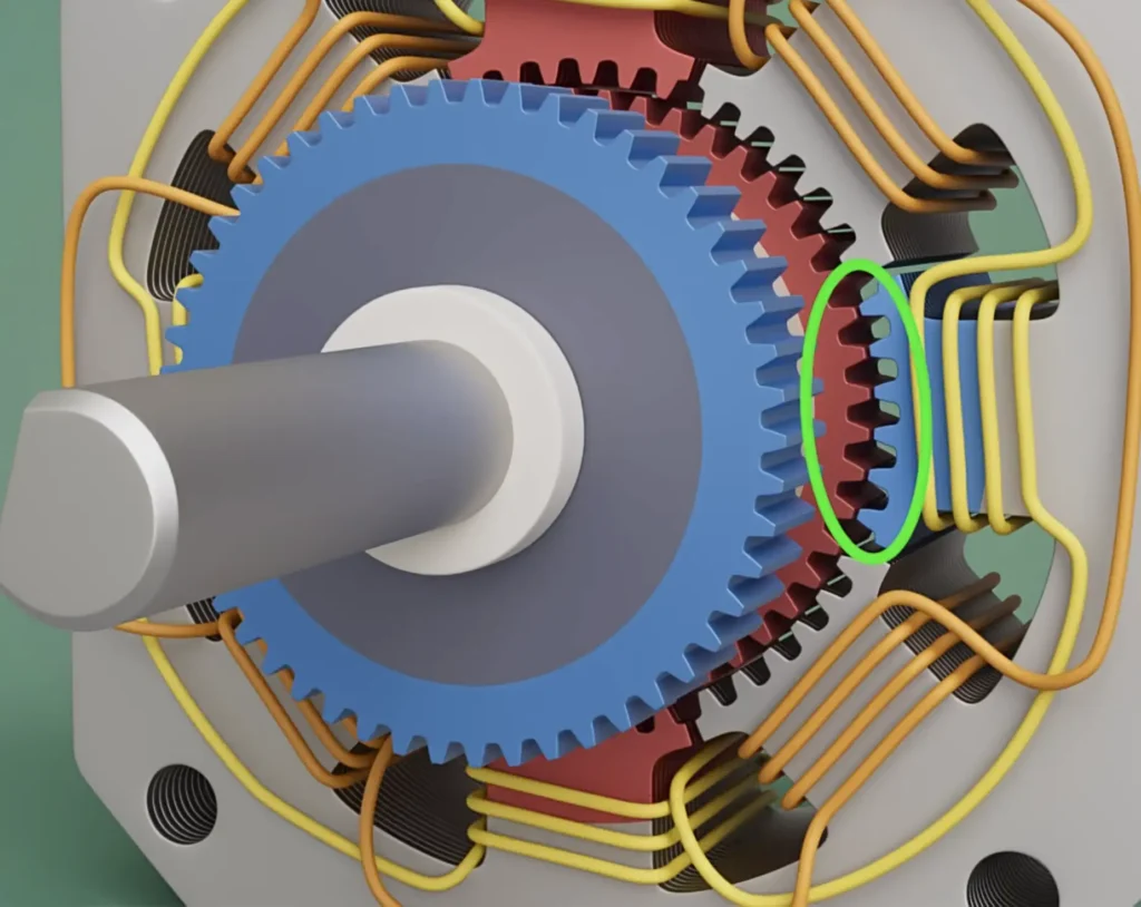
As shown in Figure 6, the rotor (red circle) has 50 teeth, and the stator (surrounding the rotor) has 48 teeth. The stator teeth are divided into 8 groups, with a 1.8° interval between each group.
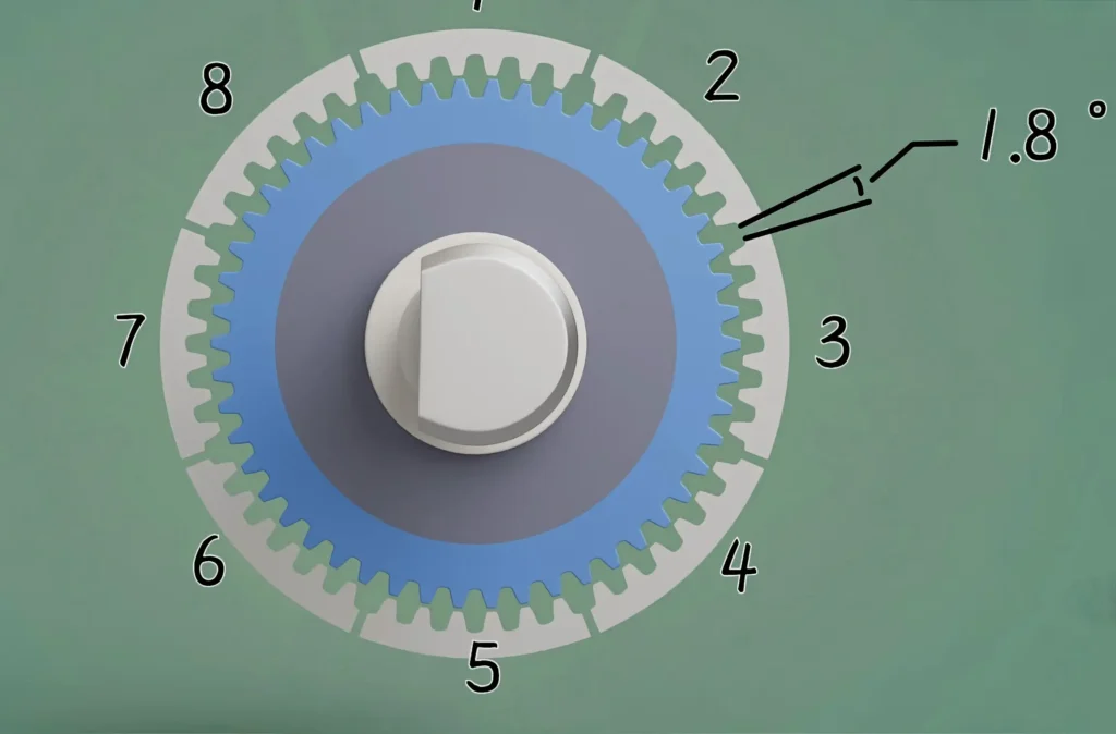
This produces a stepper motor with a much smaller step angle (Figure 7). Following the energization sequence in the figure, the rotor rotates exactly 1.8° per electrical pulse.
To boost torque, an S pole is added behind the N pole. The two permanent magnets are offset by 3.6°. When energized, the stator’s energized coil S pole attracts the front permanent magnet N pole. Simultaneously, the stator’s energized coil N pole attracts the front permanent magnet S pole (Figure 8).
NEMA Standard Dimensions for Hybrid Stepper Motors
The National Electrical Manufacturers Association (NEMA) establishes standard motor mounting dimensions. These standards serve as a global specification to ensure the interchangeability of hybrid stepper motors.
NEMA standards focus primarily on flange mounting dimensions rather than performance parameters. This approach guarantees full compatibility for mounting holes, flange size, and shaft diameter across motors of the same NEMA model.
Consequently, manufacturers can customize other aspects—such as body length, winding parameters, and output torque—without affecting the motor’s ability to fit into existing systems.
The number in a NEMA model designation corresponds to the square side length of the mounting flange measured in inches. Common industry specifications and their metric equivalents are listed below.
| NEMA Model | Flange Side Length (inch) | Metric Frame Size | Typical Applications |
| NEMA 6 | 0.6 | 14mm | Implantable medical devices, laboratory microfluidic systems, ultra-small precision actuators |
| NEMA 8 | 0.8 | 20mm | Precision medical instruments |
| NEMA 11 | 1.1 | 28mm | Security equipment, small automation mechanisms |
| NEMA 14 | 1.4 | 35mm | SMT pick-and-place machines, small 3D printers |
| NEMA 17 | 1.7 | 42mm | Desktop 3D printers, desktop CNC equipment |
| NEMA 23 | 2.3 | 57mm | Industrial automation, medium CNC equipment |
| NEMA 34 | 3.4 | 86mm | Large CNC machine tools, heavy-duty sorting equipment |
The industry also commonly refers to motors by metric frame side length (e.g., 42-step, 57-step), which belongs to the same mounting system as the corresponding NEMA model—only the naming differs.
Hybrid Stepper Motors Advantages and Disadvantages
Unlike servo motors, hybrid stepper motors achieve 1.8°/0.9° control accuracy with open-loop control, and precision can be further improved via microstepping. However, they suffer from resonance and insufficient high-speed performance.
Advantages
Hybrid stepper motors’ high industrial acceptance stems from their unique structure:
- High positioning accuracy: Step angle is determined by mechanical tooth count, with per-step error typically within ±5% and no cumulative error across steps.
- High torque at low speed: Delivers full torque at startup, unlike conventional DC motors that require a certain speed to reach rated torque—excellent for frequent start-stop applications.
- Simple control: Precise angle and speed control via pulse signals in open-loop mode, no additional encoder feedback needed.
- Durability and maintenance-free: No brush structure; virtually no consumable parts except bearing wear.
Disadvantages
Designers must address inherent drawbacks:
- Resonance risk: Prone to resonance with mechanical systems at specific pulse frequencies, causing increased noise, vibration, and even step loss. Mitigated by microstepping, gearboxes, etc.
- Efficiency and heating: Stepper drivers usually use constant-current control. Windings carry rated current even at standstill, dissipating electrical energy as heat and raising surface temperature to 60–80°C, requiring thermal management.
- Poor high-speed performance: Winding inductance increases with speed, limiting input current and causing rapid torque decay at high speeds—unsuitable for high-speed continuous operation.
- Step loss: Occurs when load torque exceeds maximum output torque, causing positioning deviation. Open-loop mode provides no real-time correction; closed-loop feedback is required for ultra-high-precision scenarios.
Comparison Between Hybrid and Permanent Magnet Stepper Motors (Same Size)
The 20mm (NEMA 8) size is highly competitive in compact precision instrument design. However, 20mm hybrid stepper motors and 20mm permanent magnet (PM) stepper motors (usually sheet-metal or claw-pole structure) differ drastically in performance.
| Performance Index | 20mm Hybrid Stepper Motor (NEMA 8) | 20mm Permanent Magnet (PM) Stepper Motor |
| Basic step angle | 1.8° (200 steps/rev) | 15° / 18° / 7.5° (20–48 steps/rev) |
| Resolution (full step) | Ultra-high; up to 1/10000° with microstepping | Low; only for coarse motion control |
| Typical holding torque | 1.5 ~ 6.0 N·cm (2.1~8.5 oz-in) | 0.5 ~ 1.5 N·cm (0.7~2.1 oz-in) |
| Mechanical accuracy | Precision-ground teeth, minimal error | Stamped claw poles, large step error |
| Drive cost | Requires constant-current driver, higher system cost | Simple voltage drive, extremely low cost |
| Typical applications | Medical pipettes, industrial dispensers, satellite gimbals | Printer paper feeding, automotive dashboards, toys |
Physically, 20mm hybrid motors use sophisticated magnetic circuit focusing with dozens of tiny magnet teeth to refine magnetic flux paths.
20mm PM motors achieve stepping via simple alternating magnetization of claw poles. Thus, in the same 20mm volume, hybrid motors deliver 3–4 times higher holding torque and an order-of-magnitude higher positioning resolution.
For engineers, choosing NEMA 8 hybrid motors means pursuing industrial-grade reliability and precision repeatability; choosing 20mm PM motors reflects prioritizing extreme cost control and simple position switching.
Additionally, hybrid motors offer better thermal stability, maintaining consistent torque under prolonged high-load operation. PM motor magnetic rotors are prone to thermal demagnetization, leading to positioning drift.
Hybrid Stepper Motors Applications
With core strengths in high precision, strong self-locking capability, easy open-loop control, and moderate cost, hybrid stepper motors are the premier choice for medium-to-low speed precision positioning.
3D Printing & Small CNC Equipment
This is the primary domain for hybrid steppers. Desktop 3D printers, laser engravers, and small CNC milling machines typically use NEMA 17 or NEMA 23 motors as industry standards.
Open-loop control provides micron-level repeatable positioning, while stable low-speed torque ensures smooth movement of nozzles and tool heads. Additionally, power-off self-locking prevents displacement after shutdown. The system cost is significantly lower than servo solutions, making it perfect for desktop precision machining.
Medical & Precision Testing Instruments
Biochemical analyzers, hematology analyzers, micro-injection pumps, ventilators, and optical testing equipment widely adopt miniature NEMA 8, 11, and 14 hybrid stepper motors. These scenarios demand extreme control accuracy and smooth operation.
Hybrid stepper motors precisely manage reagent feeding, valve switching, and probe displacement. Their non-cumulative error ensures testing accuracy, and their open-loop high reliability complies with strict medical device safety standards.
Industrial Automation & Robotics
Applications such as automatic loading mechanisms, sorting equipment, SMT pick-and-place machines, small SCARA robots, and collaborative robot joints utilize the full NEMA 17–34 range.
These motors match the rhythm of beat-based production lines and support simple multi-axis linkage. They offer stable repeatable positioning and allow for flexible selection based on load, effectively balancing torque and cost. They remain one of the most widely used actuators in industrial automation lines.
Office & Smart Consumer Devices
Printers, scanners, smart standing desks, and smart home actuators extensively use miniature hybrid stepper motors. Their simple control, low noise, and compact size meet the miniaturization and quiet operation requirements of home and office environments. Furthermore, power-off self-locking is ideal for maintaining standby positioning in smart home devices.
Hybrid Stepper MotorPerformance Optimization Tips
Maximizing hybrid stepper motor performance requires appropriate drive technology and strategic implementation. Optimizations in driving and mechanical assistance can effectively resolve vibration, resonance, step loss, and heating, thereby improving stability and accuracy.
Microstepping: Solving Vibration & Noise
Microstepping is the key technology for smooth operation—often regarded as the ultimate solution for motor noise and vibration.
Core Principle: The driver finely controls the current ratio between the two stator phases. This generates a smoothly and continuously rotating synthetic magnetic field (rather than the stepped switching found in full-step mode). This process divides the standard 1.8° full step into up to 256 microsteps (51,200 steps/rev).
Benefit: Microstepping distributes the impact energy of single-step motion across multiple tiny steps, making motor movement nearly continuous. It eliminates low-speed jitter and cogging, reducing operating noise by over 30%. This makes it ideal for quiet applications like medical instruments and office equipment.
Note: Microstepping does not proportionally improve physical positioning accuracy, which is limited by inherent factors like machining precision and magnetic field nonlinearity. However, it greatly enhances positioning resolution for fine feeding and micro-displacement control.
Vibration Suppression & Damping
For ultra-smooth applications (e.g., medical instruments, precision testing, micro gimbals), mechanical damping and software control complement microstepping to further suppress vibration and avoid resonance.
Mechanical Damping: Mounting a viscous or elastic damper on the motor shaft absorbs oscillation energy when the rotor stops. This reduces rotor oscillation and smooths the passage through resonant frequencies, preventing severe vibration and noise—especially during high-speed start-stop cycles and frequent direction reversals.
Software Ramp Control: Using S-curve acceleration/deceleration (instead of linear ramps) avoids frequency shock during startup, stopping, or speed switching. This reduces mechanical vibration and current surges, extending the life of the motor and driver.
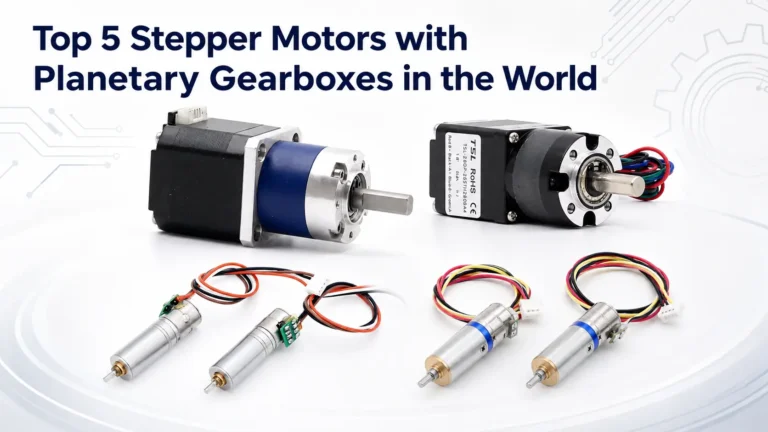
Gearbox Pairing: Adding a small gearbox (planetary or harmonic) at the output effectively suppresses resonance and boosts torque.
Closed-Loop Control
Closed-loop control is the optimal solution for mitigating open-loop step-loss risks and excessive static heating.
Core Mechanism: An encoder (incremental or absolute) is installed on the motor shaft. The driver collects the real-time rotor position via the encoder, compares it with the command position, and forms closed-loop feedback.
Key Advantages:
Eliminates Step Loss: If a mismatch is detected, the system automatically adjusts pulses and winding current to correct position deviations, ensuring precise positioning.
Optimizes Heating and Vibration: The system dynamically adjusts winding current based on the load, avoiding continuous maximum static current. It reduces current at light loads or standby to cut unnecessary heating, while precise current control further suppresses vibration.
Note: Closed-loop control increases system cost (encoder + closed-loop driver) and debugging complexity. It is best suited for ultra-high-precision, high-reliability scenarios like precision testing or robot joints. Standard applications can use open-loop control with microstepping to balance cost and performance.
Conclusion
As a classic mechatronic control component, hybrid stepper motors have not been replaced by emerging servo technologies; instead, they continue to thrive through integration with advanced semiconductor drive technology.
In miniature sizes like 20mm, they offer unrivaled precision advantages. In standardized sizes like NEMA 17, they demonstrate exceptional cost-effectiveness in mass production.
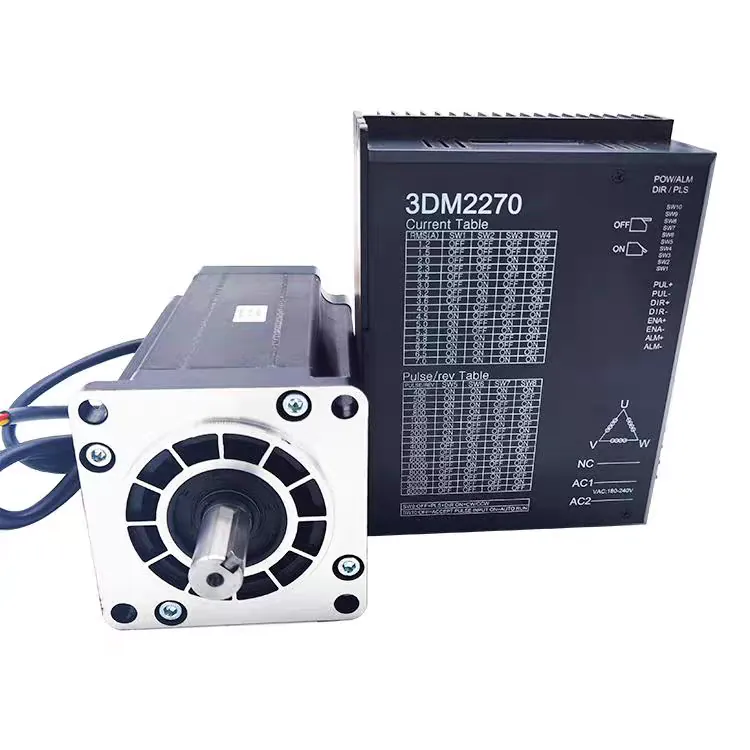
Future motors will evolve from standalone actuators into intelligent motion control terminals. These will integrate high-precision encoders, drive circuits, and industrial bus interfaces (e.g., EtherCAT, CANopen). These “integrated stepper motors” will greatly simplify industrial equipment wiring and improve system anti-interference capabilities.
For engineers in the Industry 4.0 era, mastering hybrid stepper motor magnetic circuit principles, NEMA specification selection logic, and application-specific drive optimization is fundamental to building competitive automated products.
With non-cumulative precision, strong static self-locking, and adaptability to complex environments, hybrid stepper motors will remain indispensable in the wave of smart manufacturing.
FAQ
Q1: Why does my hybrid stepper motor lose torque so rapidly at high speeds?
A: This is caused by winding inductance. As speed increases, back EMF rises, preventing the driver from pushing the full rated current into the windings quickly enough. To mitigate this, consider using a higher-voltage power supply or a motor with lower inductance.
Q2: Is it normal for my motor surface to reach temperatures of 60–80°C?
A: Yes, it is normal. Stepper drivers typically use constant-current control, meaning the motor draws full current even when stationary to maintain holding torque. As long as the temperature stays within the motor’s insulation class limits (usually Class B, 130°C), it is safe.
Q3: How can I improve positioning accuracy without changing the motor hardware?
A: Use a driver with High Microstepping capabilities. By dividing a full step into up to 256 microsteps, you significantly increase the resolution and smoothness of motion, though the ultimate accuracy is still limited by the motor’s mechanical tooth precision.
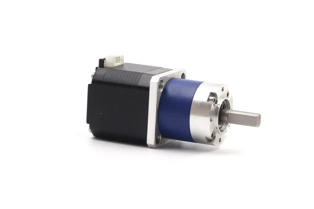
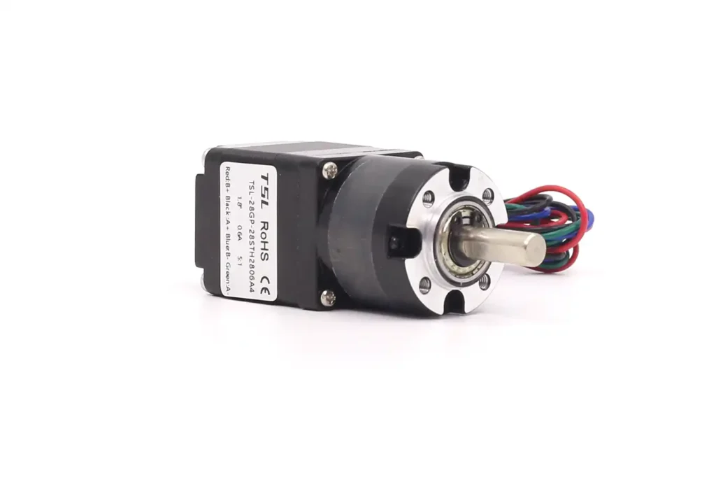
NEMA Stepper Motor
TSL Motor’s NEMA Stepper Motors are based on standard hybrid stepper motor technology.The product range covers NEMA 8 to NEMA 23.Both open-loop control solutions are supported.Encoders can be added to enable closed-loop control.This improves reliability and stability while maintaining step accuracy.
At TSL, a NEMA stepper motor is more than just a motor.
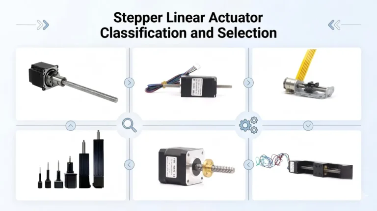
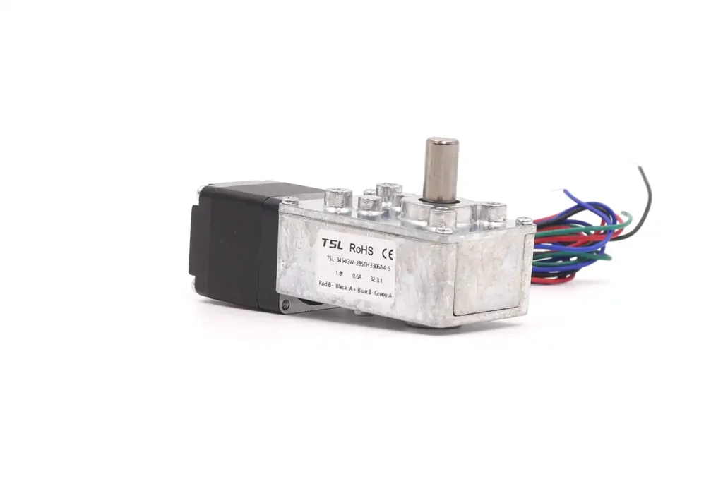
The output shaft can be customized as a lead screw or slider for linear motion.Through-shaft and hollow-shaft stepper motor designs are available.Stepper drivers can be integrated.Planetary gearboxes can also be combined.From a single motor to a complete actuator solution, the possibilities are wide open.
Bring your ideas—we’ll help you turn them into reality.