Stepper motor linear actuators have become the preferred solution in many fields such as medical equipment, 3D printing, smart homes, and industrial automation. They achieve precise positioning through open-loop control, maintain controllable costs, and feature a simple structure.
Many engineers are often dazzled by the wide variety of product models and structures during selection. In fact, you can quickly clear up your thoughts by grasping two core classification dimensions: the “motor body” and the “lead screw drive.”
Key Takeaways
- Diverse Mechanics: Stepper linear actuators utilize various transmission designs, from external drives to integrated slide tables.
- Rotary to Linear: They efficiently convert rotary stepper motion into precise linear displacement.
- Backlash Control: Selecting between ball screws and lead screws directly impacts system precision and backlash.
- Space Optimization: Integrated and miniature captive designs drastically reduce the overall physical footprint.
- Load and Speed: Mechanical structure choice determines the actuator’s load capacity and maximum velocity.
- Application Matching: Ideal selection depends heavily on balancing accuracy requirements with project budget.
- Simplified Integration: Fully integrated modular actuators streamline installation and minimize alignment errors.
Classification by Stepper Motor
All performance of a stepper motor linear actuator is built on the foundation of the motor body. Currently, stepper motors on the market mainly use permanent magnet (PM) or hybrid (HB) stepper motors. The two have essential differences in structural principles, performance parameters, and application scenarios.
Permanent Magnet Stepper Motor (PM)
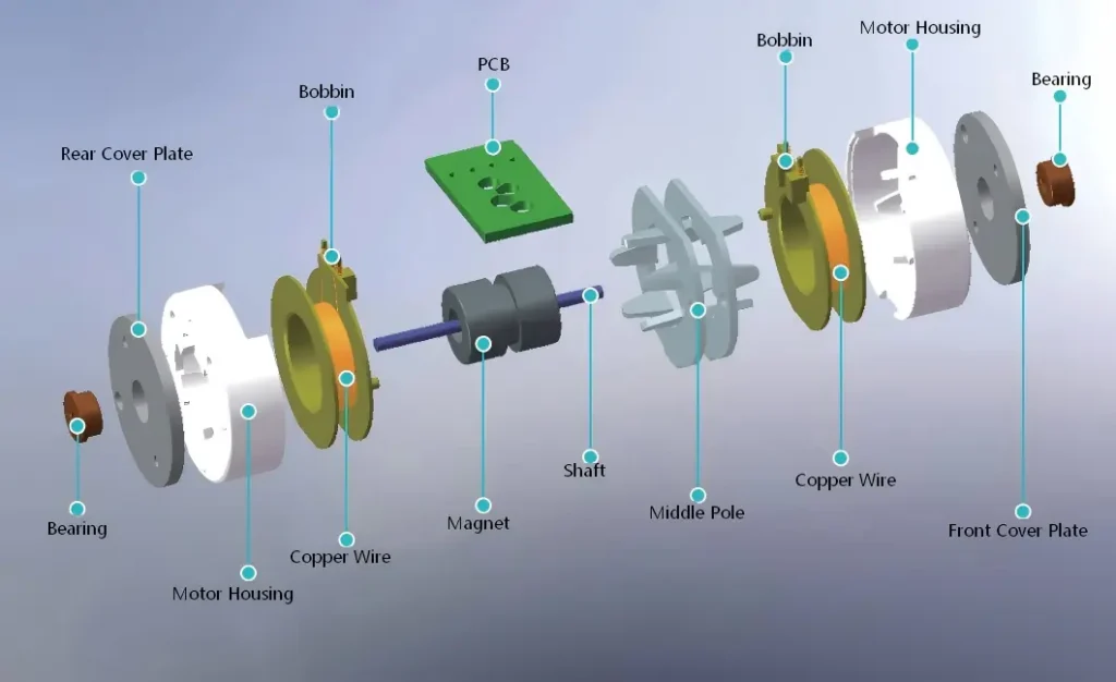
The permanent magnet stepper motor was the earliest type of stepper motor to appear. Its structure is the simplest. Its rotor is made of radially magnetized permanent magnets, usually with 2–4 pairs of magnetic poles.
The stator is wound with two-phase or three-phase windings. The magnetic field generated after the windings are energized interacts with the permanent magnet field of the rotor to drive the rotor to rotate in steps.
Main Features:
- Step Angle: Usually 1.8°
- Pull-out Torque: TSL’s 6mm diameter motor is about 1.0 gf-cm, and the 20mm diameter motor is about 25 g-cm.
- Operating Frequency: The maximum operating frequency generally does not exceed 500Hz; torque drops sharply after exceeding this.
- Power Consumption Characteristics: Small no-load current and low heat generation, but the current increases significantly after loading.
Pros and Cons Analysis:
- Advantages: Simple structure, few parts, low production cost, low noise, and low vibration.
- Disadvantages: Large step angle, low positioning accuracy, slow dynamic response, and not suitable for high-speed motion.
Typical Application Scenarios:
- Consumer Electronics: Water level adjustment in household humidifiers, opening and closing control of electric curtains, and damper adjustment in air purifiers.
- Office Equipment: Paper feed mechanism in small printers, and lens movement in scanners.
- Simple Industrial Control: Switching of small valves, and angle adjustment of indicator lights.
Hybrid Linear Stepper Motor (HB)
The hybrid stepper motor combines the advantages of permanent magnet and reactive stepper motors. It is currently the most technologically mature and widely used type of stepper motor.
Its rotor consists of two parts: the middle is an axially magnetized permanent magnet, and both ends are made of soft magnetic material with teeth and slots. The stator also has a corresponding tooth and slot structure.
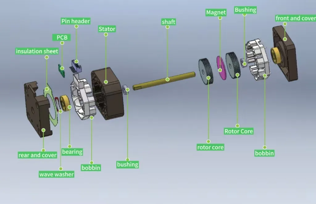
The magnetic field generated after the windings are energized interacts with both the permanent magnet and the teeth of the rotor simultaneously, producing greater torque and a smaller step angle.
Main Features:
- Step Angle: The standard step angle of TSL’s hybrid stepper motor is 1.8° and 0.9°. The step angle can be made even smaller through microstepping drives.
- Holding Torque: TSL’s NEMA 6 stepper motor is about 0.0058 N·m, and the NEMA 23 stepper motor is about 3 N·m.
- Operating Frequency: The maximum operating frequency can reach 2000–3000Hz, and operation is smoother under microstepping drives.
- Power Consumption Characteristics: High static current and obvious heat generation, usually requiring heat dissipation measures.
Pros and Cons Analysis:
- Advantages: Small step angle and high positioning accuracy; large output torque and smooth low-speed operation; good dynamic performance and fast response speed; accuracy and smoothness can be further improved through microstepping drives.
- Disadvantages: Complex structure and high production cost; high static current and severe heat generation; holding torque is small after power failure, requiring an extra brake under heavy loads.
Typical Application Scenarios:
- 3D Printing: XYZ three-axis movement of the print head.
- Medical Equipment: Sample delivery in medical analyzers, and precise injection in syringe pumps.
- Industrial Automation: Precision dispensing machines, automatic screw machines, and small CNC machine tools.
- Testing Equipment: Lens movement in optical testing instruments, and position adjustment of sensors.
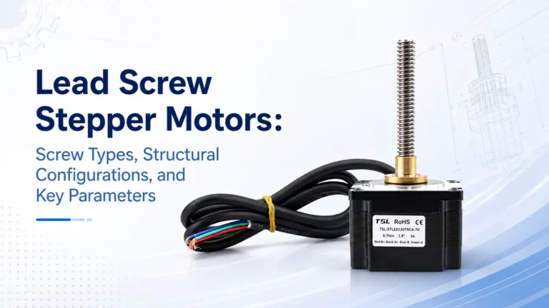
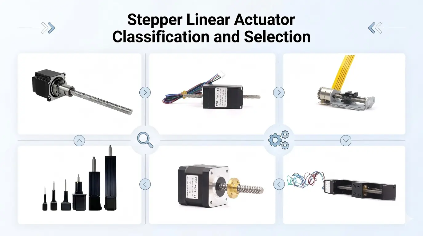
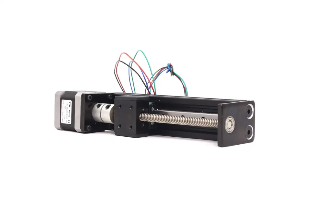
Classification by Lead Screw Drive Structure
The lead screw is the “heart” of the stepper motor linear actuator. It directly determines the thrust, accuracy, efficiency, and lifespan of the actuator. According to the integration and movement form of the lead screw and the motor rotor, stepper motor linear actuators are mainly divided into the following four core structures.
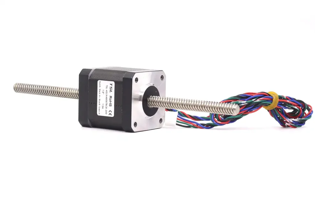
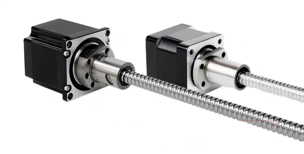
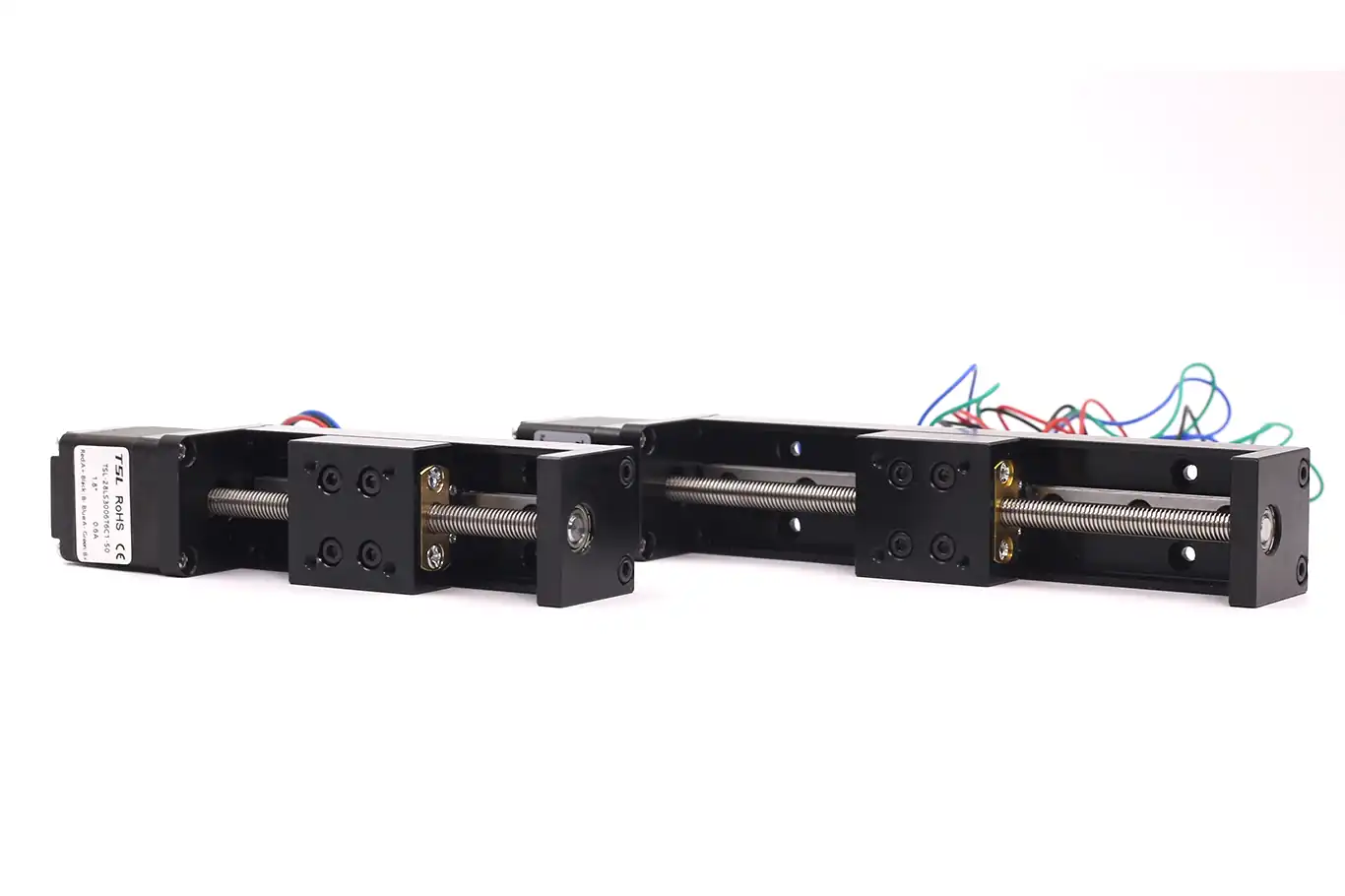
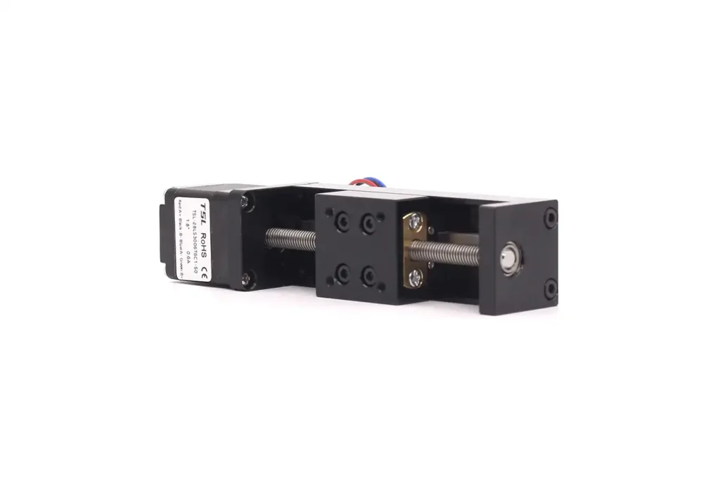
External Drive Linear Stepper Motor
The external drive linear stepper motor is the most basic structural form. Its lead screw is integrated with the motor rotor as the output shaft of the motor. The nut is an independent component that users need to install on the load themselves.
When the motor rotates, the lead screw rotates with it. If the nut is fixed by an external device and cannot rotate, the nut will move linearly along the lead screw.
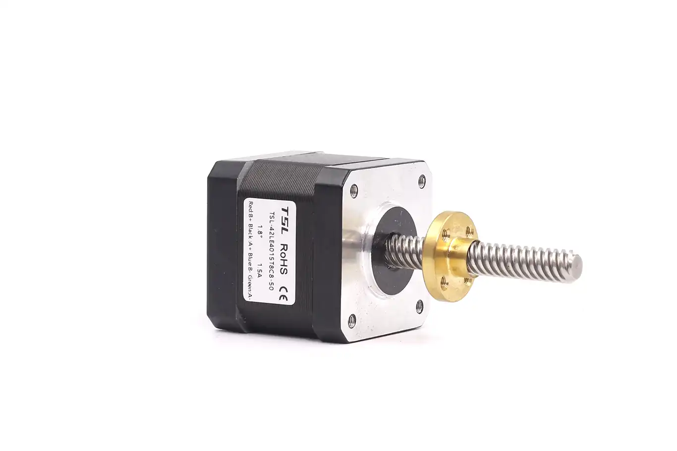
Main Features:
- Movement Mode: Lead screw rotates, nut moves linearly.
- Stroke Length: Theoretically not limited by the motor itself, it can be customized according to needs, up to several meters.
- Lead Screw Type: Usually adopts trapezoidal lead screw, with a lead range of 1–20mm.
- Thrust Range: TSL’s NEMA 11 stepper motor linear actuator is about 16–90N, and TSL’s NEMA 23 stepper motor linear actuator is about 300–760N.
Pros and Cons Analysis:
- Advantages: Simplest structure and lowest cost; flexible stroke length, customizable long stroke; diverse installation methods, suitable for various non-standard designs.
- Disadvantages: Users need to design the anti-rotation and installation structure of the nut themselves; the lead screw is exposed and easily contaminated by dust and oil; accuracy is greatly affected by installation errors.
Typical Application Scenarios:
- Cargo channel pushing mechanism in vending machines.
- Lifting control of small lifting platforms.
- Push-pull mechanism of drawer-type equipment.
- Simple material conveying devices.
Selection Note: The external drive linear stepper motor is suitable for scenarios with long strokes, sufficient installation space, and low accuracy requirements. When designing, you must ensure that the anti-rotation structure of the nut is reliable. Otherwise, it will cause the lead screw to idle and fail to achieve linear motion.
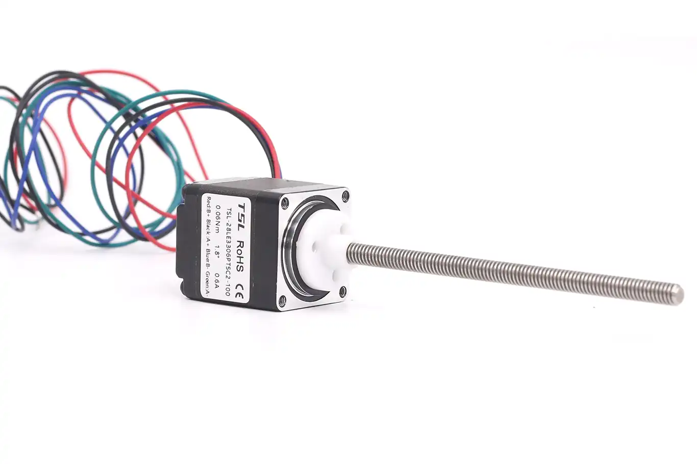
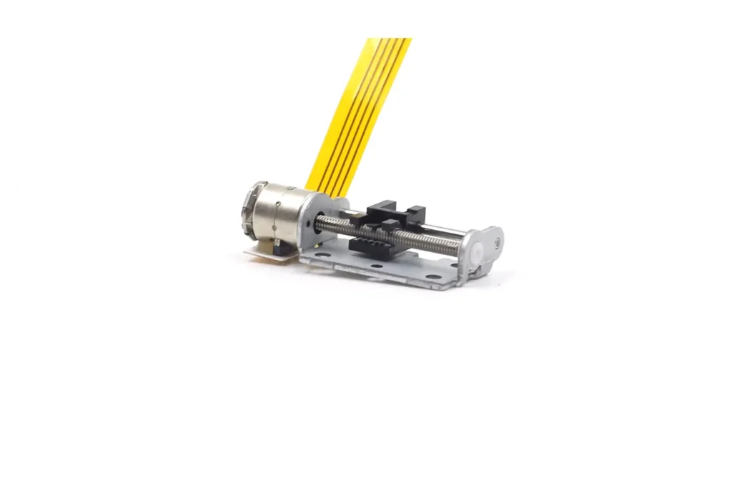
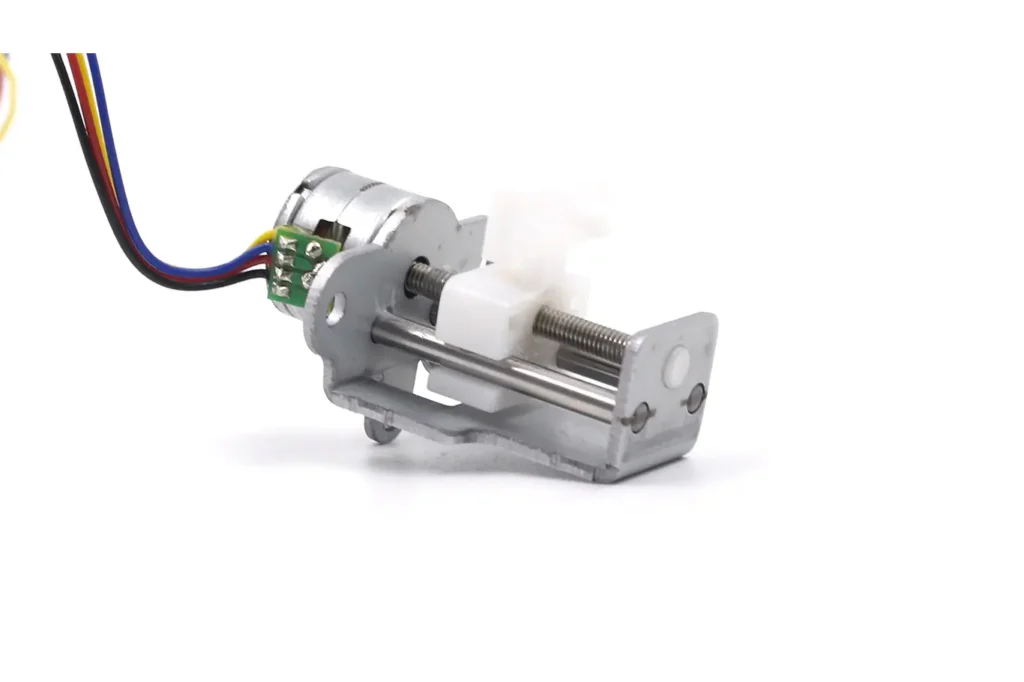
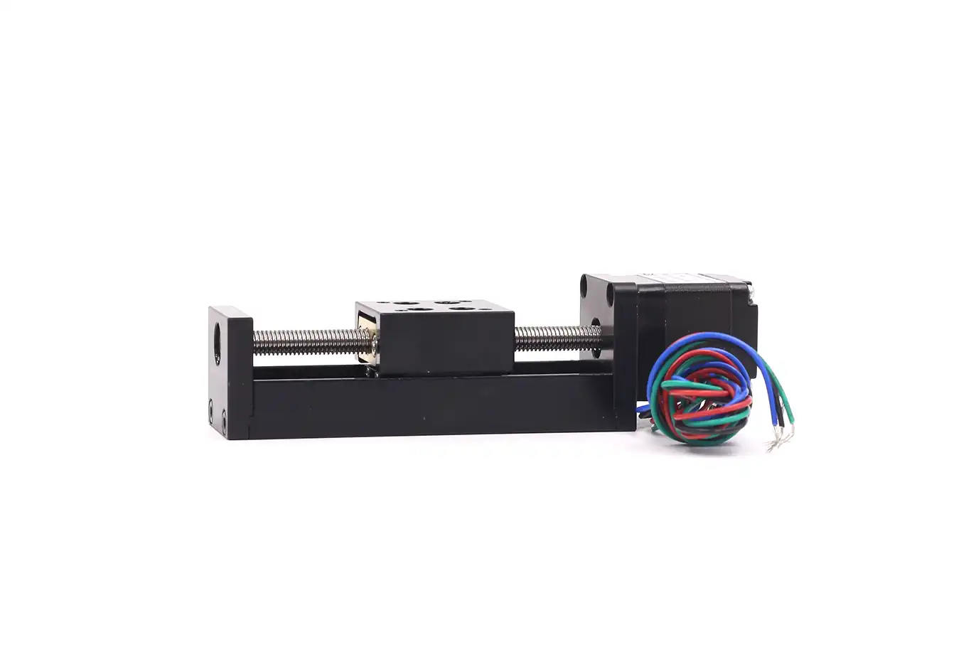
Non-Captive Linear Stepper Motor
The structure of the non-captive linear stepper motor is exactly opposite to that of the external drive type. Its nut is integrated with the motor rotor, and the lead screw shaft passes through the nut in the center of the motor rotor.
When the motor rotates, the nut rotates with it. If the lead screw is fixed by an external device and cannot rotate, the lead screw will move linearly.
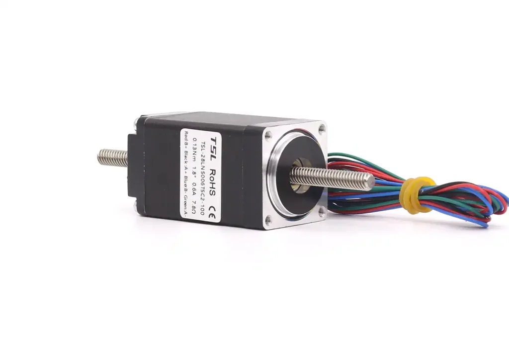
Main Features:
- Movement Mode: Nut rotates, lead screw moves linearly.
- Stroke Length: Limited by the length of the lead screw shaft, usually not exceeding 500mm.
- Lead Screw Type: Usually adopts trapezoidal lead screw, with a lead range of 1–10mm.
- Thrust Range: TSL’s NEMA 11 motor is about 35–79N, and TSL’s NEMA 17 motor is about 100–298N.
Pros and Cons Analysis:
- Advantages: Compact structure and small axial size; thrust acts directly on the lead screw shaft, providing large output thrust; the lead screw shaft can extend bidirectionally to achieve bidirectional movement.
- Disadvantages: Needs an external device to prevent the lead screw from rotating; rigidity of the lead screw shaft is poor, making it easy to bend during long strokes; the lead screw is exposed, leading to poor protection performance.
Typical Application Scenarios:
- Fine-tuning mechanism of precision displacement stages.
- Switching control of valve actuators.
- Focusing mechanism of optical lenses.
- Injection mechanism of medical syringe pumps.
Selection Note: The non-captive linear stepper motor is suitable for scenarios with short strokes, high thrust requirements, and limited installation space. In long-stroke applications, it is necessary to add support structures for the lead screw to prevent it from bending and deforming.
Captive Linear Stepper Motor
The captive linear stepper motor is an integrated product developed on the basis of the non-captive type. Its nut is integrated with the motor rotor, the lead screw shaft passes through the nut in the center of the motor rotor, and the front end of the lead screw shaft connects to a plunger (push rod).
The plunger is supported and guided by a guide sleeve on the motor, and the guide sleeve also plays an anti-rotation role. When the motor rotates, the nut drives the lead screw shaft and plunger to perform linear telescopic movement.
Main Features:
- Movement Mode: Nut rotates, plunger performs linear telescopic movement.
- Stroke Length: Limited by the length of the plunger, usually not exceeding 300mm.
- Lead Screw Type: Usually adopts trapezoidal lead screw, with a lead range of 1–5mm.
- Thrust Range: 20mm motor is about 30–100N, 35mm motor is about 50–200N, and 42mm motor is about 100–400N.
Pros and Cons Analysis:
- Advantages: Highest integration, built-in anti-rotation and guiding structure, extremely convenient installation; no need for users to design additional mechanical structures, plug-and-play; the movement form is the extension and retraction of the push rod, intuitive and easy to use.
- Disadvantages: Stroke is usually short; rigidity of the plunger is poor, unable to bear radial force; protection performance is average, not suitable for harsh environments.
Typical Application Scenarios:
- Electric lifting devices in smart homes.
- Adjustment mechanism of car seats.
- Massage head drive of massage equipment.
- Actuators for small valves.
Selection Note: The captive linear stepper motor is suitable for scenarios with short strokes, limited installation space, and high convenience requirements. During use, you should avoid radial force on the plunger. Otherwise, it will accelerate the wear of the guide sleeve and affect the service life.
Ball Screw Linear Stepper Motor
The ball screw linear stepper motor is a high-performance linear actuator. Unlike the previous three actuators using trapezoidal lead screws, it uses balls as rolling elements to change the sliding friction between the screw and the nut into rolling friction, thereby greatly improving transmission efficiency and accuracy.
The ball screw linear stepper motor usually adopts an external drive structure. That is, the lead screw is integrated with the motor rotor as the motor output shaft, and balls are installed inside the nut. When the motor rotates, the lead screw drives the balls to roll within the raceway of the nut, pushing the nut to move linearly.
Main Features:
- Transmission Efficiency: Can reach over 90%, much higher than the 30%–40% of trapezoidal lead screws.
- Positioning Accuracy: Standard grade can reach ±0.05mm/300mm, and precision grade can reach ±0.01mm/300mm.
- Repeatability: Can reach ±0.005mm.
- Lifespan: 5–10 times that of trapezoidal lead screws.
- Thrust Range: 42mm motor is about 200–800N, and 57mm motor is about 500–2000N.
Pros and Cons Analysis:
- Advantages: Extremely high transmission efficiency and low heat generation; high positioning accuracy and repeatability; low wear and long lifespan; smooth operation, low noise, and good high-speed performance.
- Disadvantages: High cost, about 2–3 times that of trapezoidal lead screw actuators; weak impact resistance, unable to bear excessive shock loads; requires regular lubrication.
Typical Application Scenarios:
- Feed mechanism of high-precision CNC machine tools.
- Wafer transport in semiconductor equipment.
- Displacement stages of precision testing instruments.
- Dispensing head drive of high-speed dispensing machines.
Selection Note: The ball screw linear stepper motor is suitable for high-end applications with high requirements for accuracy, efficiency, and lifespan. During use, you should avoid shock loads and perform regular lubrication maintenance.
Stepper Motor Linear Stage Modules
For many standardized applications, a separate linear stepper motor also needs to be paired with guide rails, mounting bases, limit switches, and other components before it can be used. To simplify the design and installation process, highly integrated products have appeared on the market—stepper motor linear stage modules.
The stepper motor linear stage module integrates the stepper motor, lead screw, linear guide rail, mounting plate, limit switch, and other components together to form a complete linear motion unit. Users only need to fix the load on the stage, connect the power supply and the driver, and it is ready to use, which greatly shortens the equipment development cycle.
Classification by Motor Type
A linear stage module is a single-axis positioning unit formed by deeply integrating a linear stepper motor with linear guide rails, a support base, limit sensors, and other parts. In the configuration of stage modules, the power source can be mainly divided into two categories: permanent magnet stage modules and stepper (hybrid) stage modules.
- Permanent Magnet Stage Module: Adopts permanent magnet stepper motor, low cost, low accuracy, small thrust, suitable for simple light-load applications.
- Hybrid Stage Module: Adopts hybrid stepper motor, high accuracy, large thrust, smooth operation, currently the mainstream product on the market.
Classification by Connection Method
When designing and applying stage modules, the connection process between the motor and the feed screw has a crucial impact on the system’s mechanical rigidity, backlash, and spatial dimensions.
- Coupling Connected Type: The motor and the lead screw are connected through a coupling, which is flexible in structure and convenient for replacing motors and lead screws of different specifications. However, the coupling will introduce a certain backlash, affecting positioning accuracy.
- Integrated Type: The lead screw is directly integrated with the motor rotor (i.e., external drive structure), which makes the structure more compact, eliminates the backlash brought by the coupling, and offers higher accuracy. However, the motor and lead screw cannot be replaced separately, leading to higher maintenance costs and stricter process requirements for precise coaxiality.
Classification by Drive and Guide Type
The guidance and transmission pairs at the bottom of the stage module determine its motion smoothness, efficiency, and self-locking characteristics. Stages are mainly divided into ball-type stages and general-type (nut) stages.
- Trapezoidal Lead Screw Stage: Adopts trapezoidal lead screw drive, low cost, simple structure, suitable for low-to-medium accuracy, low-speed, and light-load applications.
- Ball Screw Stage: Adopts ball screw drive, high accuracy, high efficiency, long lifespan, suitable for high-precision, high-speed, and heavy-load applications.
How to Choose the Right Stepper Motor Linear Actuator
The selection of stepper motor linear actuators and stage modules is a systematic project that requires a comprehensive consideration of multiple factors such as performance, cost, installation space, and reliability. When faced with complex technical datasheets provided by manufacturers, many engineers often do not know where to start.
Detailed Explanation of Core Selection Parameters
The following are 6 core parameters that must be closely focused on during selection. Each parameter directly determines whether the actuator can meet the application requirements:
Effective Stroke:
The maximum linear distance that the stage or actuator can safely move. When selecting, you need to reserve a buffer distance of 10%–20% based on the actual required stroke to prevent hard collisions at both ends from damaging the screw, bearings, or motor rotor.
Maximum Load:
The maximum weight that the actuator can stably bear. Special attention must be paid to distinguishing between horizontal and vertical loads. Under vertical loads, the load-bearing capacity of the actuator usually drops by 30%–50%, and you must additionally consider whether the holding torque after power failure is sufficient to prevent the load from sliding down.
Positioning Accuracy:
The absolute error of the actuator moving to the theoretically designated position, mainly determined by the lead error of the screw, processing accuracy, and installation error.
Repeatability:
The error of the actuator moving back and forth to the same theoretical position multiple times. It is the most critical indicator for measuring system stability and is especially important for automation applications that require repetitive positioning.
Maximum Speed:
The highest movement speed that the actuator can reach, determined jointly by the maximum operating frequency of the motor and the lead screw pitch.
Thrust:
The maximum axial thrust that the actuator can output. When selecting, a margin of 20%–30% should be left according to the actual load to avoid severe heat generation and shortened lifespan caused by long-term overload operation of the motor.
Universal Five-Step Selection Method
Following these standardized steps can help engineers quickly narrow down the selection scope and avoid blind choices:
Clarify and Quantify Core Requirements:
First, convert all application requirements into quantifiable technical indicators, including: effective stroke, maximum thrust, maximum operating speed, positioning accuracy, installation space limits , and working environment (temperature, humidity, dust).
Choose Motor Body Type:
Give priority to permanent magnet (PM) stepper motors for light loads (<50N), low accuracy, and low-cost requirements. Choose hybrid (HB) stepper motors for medium-to-high loads (above 50N), high accuracy , and high dynamic response requirements.
Choose Motor-Screw Integrated Structure:
Give priority to the external drive type for long stroke requirements; choose the non-captive type for short strokes with large thrust and extremely limited axial installation space; choose the captive type if you pursue plug-and-play convenience without designing additional anti-rotation structures; choose the ball screw type for high-precision, high-efficiency, and long-lifespan requirements.
Choose Integration Level:
Give priority to integrated stage modules for standardized, mass-production applications, which can significantly shorten development and installation cycles. Choose separate linear stepper motors to build the system yourself for non-standard customization, special installation requirements, or extremely cost-sensitive applications.
Comprehensive Cost and Reliability Evaluation: On the premise of meeting all performance requirements, prioritize the most cost-effective solution while considering the product’s lead time, after-sales service, and long-term reliability.
Typical Operating Condition Selection Matrix
To help engineering design personnel make quick and accurate decisions when facing complex technical specifications, the following table summarizes the design and selection matrix for mainstream industrial and consumer electronics operating conditions:
| Application Scenario (Key Requirements) | Recommended Power Source | Recommended Screw Structure | Coupling Method | Transmission Type | Core Selection Logic |
| High-precision 3D Printing, CNC Milling & Engraving(High-frequency reciprocation, micro-step accuracy, low backlash) | Hybrid Stepper (HB) | External Drive | Integrated Direct Drive | Ball Screw | Low friction for high-frequency motion; direct drive + ball screw eliminates micro-step backlash |
| Pipette Analyzers, Clean Medical Valves(Low noise, oil-free, low speed) | Permanent Magnet (PM) | Captive | Integrated Direct Drive | Resin Lead Screw (Silent/Oil-free) | Medical-grade quiet and clean operation; PM motor + resin nut offers best cost-performance |
| Semiconductor Packaging Probes, Compact Multi-axis Test Rigs(Minimal space, micron-level accuracy) | Hybrid Stepper (HB) | Non-captive | Integrated Direct Drive | Anti-backlash Lead Screw | Maximizes space savings; non-captive + direct drive ensures compactness and accuracy |
| Heavy-load Conveying, Vertical Lifting(High thrust, impact resistance, high reliability) | Hybrid Stepper (HB) | External Drive | Coupling Connection | Roller Screw / Heavy-duty Ball Screw | Coupling isolates impact loads; protects motor's internal precision components |
| Application Scenario (Key Requirements) | Recommended Power Source | Recommended Screw Structure | Coupling Method | Transmission Type | Core Selection Logic |
Avoiding Common Selection Misconceptions
In the actual selection process, special attention should be paid to the following common misconceptions:
Misconception 1: The smaller the step angle, the higher the system accuracy.
In reality, the final positioning accuracy of the system is a comprehensive result of the motor step angle, lead screw pitch, processing accuracy, and installation error. A hybrid stepper motor with a 1.8° step angle can fully reach or even exceed the actual use accuracy of a 0.9° step angle motor through 16-microstep or 32-microstep drives.
Misconception 2: The larger the thrust, the better.
Excessive thrust will not only increase unnecessary costs and power consumption but also cause severe motor heat generation and shorten service life.
Misconception 3: Ball screws are definitely better than trapezoidal lead screws.
Although ball screws have obvious advantages in accuracy, efficiency, and lifespan, their cost is 2–3 times that of trapezoidal lead screws, and their impact resistance is poor. In low-speed, light-load scenarios with low accuracy requirements, trapezoidal lead screws are a more cost-effective choice.
Misconception 4: Integrated direct connection is definitely better than coupling connection.
Although integrated direct connection eliminates coupling backlash and improves accuracy, in applications where impact loads exist, the coupling can play a buffering role and protect the motor, preventing damage to the precise internal components of the motor.
Conclusion
The stepper motor linear actuator is an indispensable core component in automation equipment. Although there are many types, they are essentially a combination of “stepper motor + lead screw drive.” Different types of products have obvious differences in structural principles, performance parameters, and application scenarios.
During actual selection, engineers need to deeply understand the technical details and performance boundaries of different types of products, and make comprehensive considerations based on specific application requirements to choose the most suitable product.
With the continuous development of automation technology, stepper motor linear actuators are also making continuous progress toward higher accuracy, higher efficiency, smaller size, and higher integration. They will play an important role in more fields in the future.
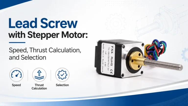
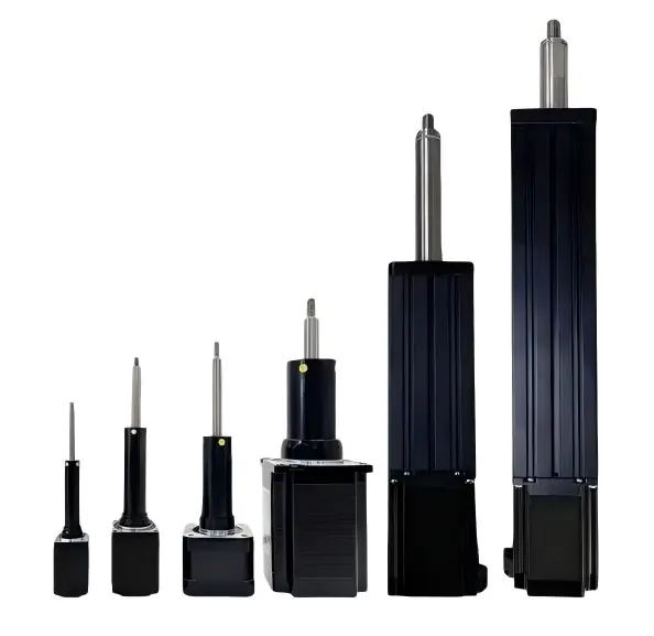
Stepper Motor Linear Actuator
TSL Motor’s Stepper Motor Linear Actuators convert rotary motion into precise linear movementby using lead screws or slider mechanisms.From micro stepper linear actuators for camera iris control,to NEMA stepper motor linear actuators for 3D printers and automation systems.Different sizes and thrust levels support different applications.
At TSL, linear actuators go beyond mechanical structures.
Standard wires or FPC flexible cables are available.Each solution can be optimized for system-level requirements.
Here, you don’t need to worry about technical challenges.
Our engineering experts work closely with you.We solve problems together and develop solutions together.