Published: DECEMBER 3, 2025
Updated:SEPTEMBER 19, 2026
Brushless outrunner motors place the permanent magnets in a rotating outer shell. Their larger air-gap radius provides a natural direct-drive torque advantage, making them popular in drones, gimbals, fans and compact rotary systems.
That advantage comes with trade-offs. Higher rotor inertia, cooling, dynamic balance, magnet retention and controller matching all require attention. In our view, an outrunner is best suited to applications that need a short axial package and strong torque at moderate speed—not simply because its Kv is low. This guide explains its benefits, limitations and practical selection points.
Key Takeaways
- A larger air-gap radius gives outrunners an advantage in direct-drive torque, but does not guarantee higher torque in every design.
- The short axial package is useful, although the outer rotor generally creates higher rotational inertia.
- Continuous output depends on winding temperature, cooling and duty cycle—not peak power alone.
- High-speed operation requires careful control of rotor balance, magnet retention, bearing limits and surface speed.
- Kv is only a speed constant. Final selection must also consider torque, current, voltage, ESC compatibility and the actual load.
What Is a Brushless Outrunner Motor?
A brushless outrunner motor places the stationary stator at the center and the permanent-magnet rotor around it. The outer rotor bell, shaft and load interface rotate together while an ESC electronically commutates the stator windings.
Placing the air gap farther from the shaft increases the effective torque radius and allows the motor to produce useful direct-drive torque within a relatively short axial package. However, “outrunner” describes the motor structure—not a fixed torque, speed or efficiency level. Actual performance still depends on motor diameter, active length, pole count, winding design, magnetic loading, current and cooling.
TSL Motor supplies outrunner rotor BLDC motors for applications ranging from drones and gimbals to fans and compact direct-drive mechanisms.
Stator
The stator normally consists of a laminated steel core and three-phase copper windings. It remains stationary while the controller energizes the phases in sequence to create a rotating magnetic field.
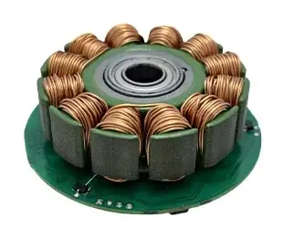
Copper loss and part of the iron loss are generated in the stator. Continuous torque therefore depends strongly on the thermal path from the stator core to the mounting structure and surrounding air. An open drone motor may benefit from propeller airflow, while an enclosed outrunner relies more heavily on conduction through its stator support and mounting interface.
Rotor
The rotor usually consists of a steel bell with permanent magnets bonded to its inner surface. The bell may also provide the mounting interface for a propeller, fan, wheel or other load.
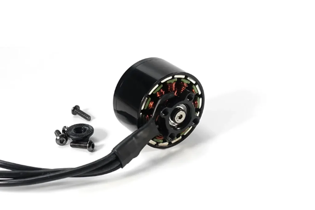
Its larger magnetic radius contributes to direct-drive torque, but it also places more mass farther from the rotational axis. Rotor stiffness, concentricity, magnet retention and dynamic balance become increasingly important as speed rises.
Bearings and Shaft Support
The bearing system supports the rotating bell and maintains a stable air gap. It may need to withstand radial load, axial load and bending moments produced by the attached load.
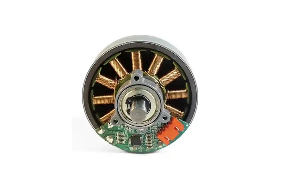
Bearing spacing, preload, shaft stiffness and rotor balance all influence runout, vibration, noise and service life. These limits should be checked using the actual mounting direction and load—not from motor torque alone.
ESC and Feedback
An outrunner requires an ESC or servo drive to switch current through its phases. Commutation may use back-EMF estimation, Hall sensors or an encoder.
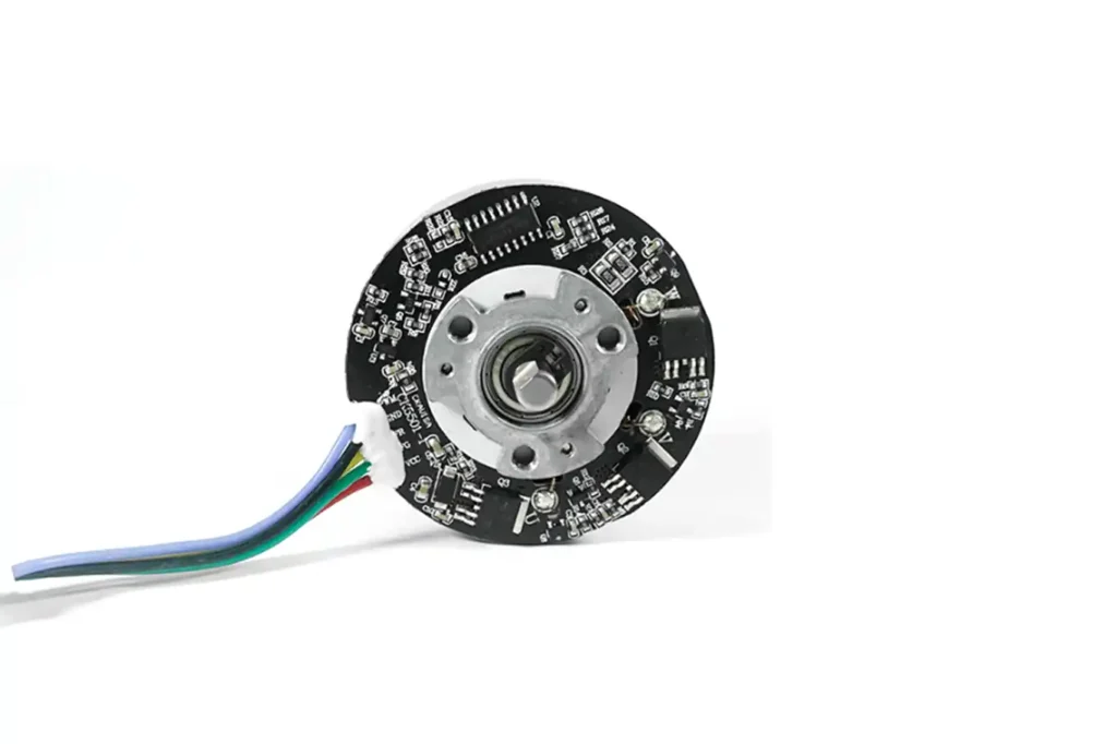
Sensorless control works well once sufficient back EMF is available, but startup and very-low-speed operation can be more demanding. Hall or encoder feedback is preferable when the application requires controlled startup, low-speed stability or position control.
For a direct structural comparison, see Inrunner vs Outrunner Motors: Torque and Selection Rules.
How Does a Brushless Outrunner Motor Work?
The electromagnetic principle is the same as that of other permanent-magnet brushless motors. The main difference is mechanical: the magnet-carrying outer bell rotates around the stationary stator.
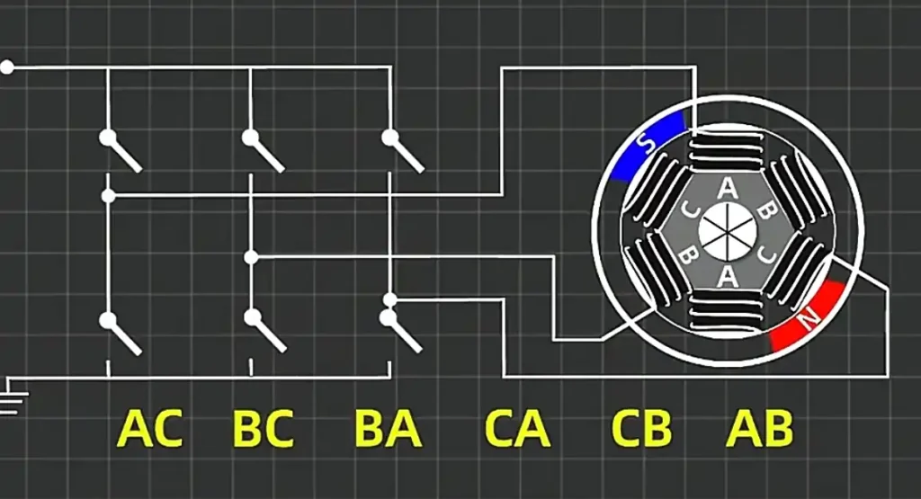
Step 1: Powering and Initial Position Detection
Before applying the correct phase current, the controller needs to know or estimate the rotor position. A sensored motor obtains this information from Hall sensors or an encoder.
A sensorless ESC cannot directly measure back EMF at standstill, so it normally begins with rotor alignment and an open-loop startup sequence. Back-EMF detection becomes reliable only after the rotor reaches sufficient speed.
Step 2: Generating a Rotating Magnetic Field
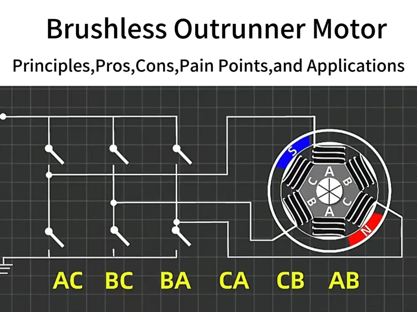
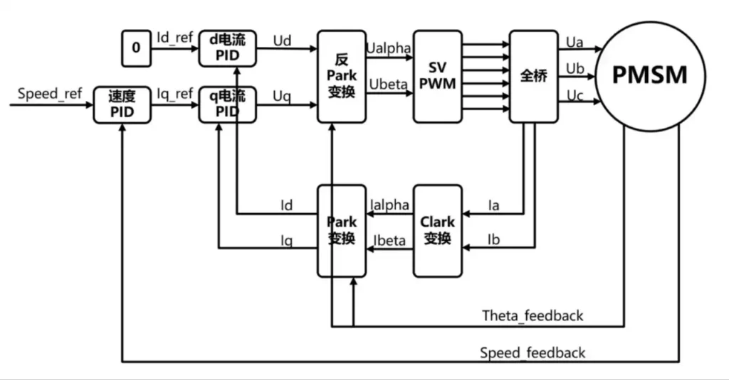
The ESC uses a three-phase inverter to control current through the stator windings. Depending on the controller, the motor may use six-step commutation, sinusoidal control or field-oriented control.
Six-step commutation switches between six electrical states. Sinusoidal and FOC drives regulate phase current more continuously, which can reduce torque ripple and improve low-speed control when correctly tuned.
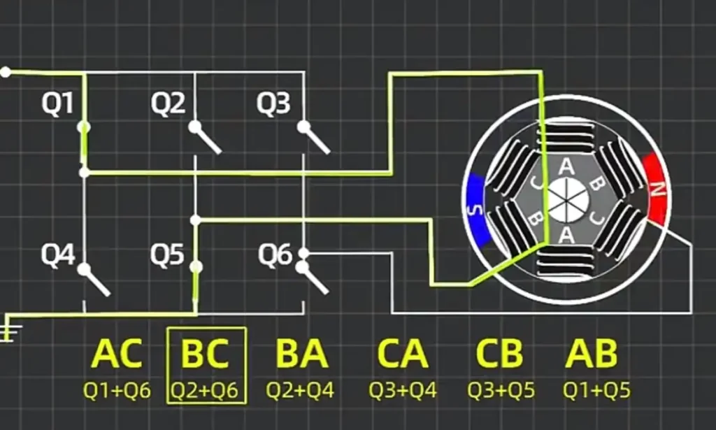
- Taking a three-phase star connection and the typical six-step commutation (switching every 60° electrical angle):
- AC Phase Powering: (Q1+Q6 switches closed). Current flows from A to C. A magnetic field is generated in a specific direction.
- BC Phase Powering: (Q2+Q6 switches closed). Switches to B and C. The magnetic field rotates 60°.
- BA, CA, CB, AB Phase Powering: The sequence continues, changing current direction to maintain rotation.
Step 3: Magnetic Force Drives the Rotor
The stator’s rotating magnetic field interacts with the rotor’s static magnetic field (permanent magnets):
- Attraction occurs when the stator’s N pole aligns with the rotor’s S pole.
- Repulsion occurs when the stator’s N pole approaches the rotor’s N pole.
- These forces combine to drive the outer rotor (casing) in continuous rotation.
Step 4: Real-time Commutation and Closed-Loop Control
Hall sensors continuously detect the rotor’s position. This feedback goes to the controller.
- The controller precisely adjusts the winding power timing based on the position signal. This ensures the magnetic field is always “pulling” the rotor forward.
- Sensorless schemes estimate the position. They do this by detecting the zero-crossing point of the Back EMF (Electromotive Force) generated by the windings.
Step 5: Speed and Torque Regulation
- Speed Control: The controller adjusts the average voltage applied to the windings via PWM (Pulse Width Modulation). This changes the current magnitude, thereby adjusting the speed.
- Torque Control: Higher current leads to a stronger magnetic field. This results in a greater output torque (within the magnetic saturation limit).
Advantages of Brushless Outrunner Motors
The main advantages of an outrunner come from its larger air-gap radius and rotating outer shell. These characteristics can simplify a drive system, but only when the motor is matched to the required speed, torque and duty cycle.
Larger Torque-Producing Radius
The basic mechanical relationship is:
Torque = Tangential force × Radius

Because the air gap of an outrunner is positioned closer to the motor’s outer diameter, the electromagnetic force acts through a longer moment arm. If two motors generate similar tangential force, the motor with the larger effective air-gap radius produces more torque.
This provides an important direct-drive advantage, but rotor diameter alone does not determine final torque. Active length, winding design, magnetic loading, current and temperature still limit the usable output.
Short Axial Package
An outrunner can provide a relatively large torque-producing diameter without requiring a long motor body. This is useful when axial installation space is limited but sufficient radial space is available.
The topology is therefore common in gimbals, drone propulsion systems, fans and compact rotary mechanisms.
Direct Load Integration
The rotating bell can provide a direct mounting surface for a propeller, fan, wheel or other load. When the required speed and torque match the motor’s natural operating range, a gearbox or additional coupling may not be necessary.
Removing unnecessary transmission components can reduce:
- Overall length and weight;
- Gear noise and mechanical losses;
- Backlash and transmission compliance;
- Assembly complexity and part count.
This benefit does not mean that every outrunner can replace a geared motor. Applications requiring very low output speed or exceptionally high torque may still need mechanical reduction.
Smooth Operation at Moderate Speed
Many outrunners use multiple pole pairs. When combined with suitable rotor-position feedback and a correctly tuned sinusoidal or FOC controller, this can provide smooth torque at moderate and low speeds.
Smooth operation is not guaranteed by the outrunner structure alone. Cogging torque, winding design, sensor resolution and controller tuning still affect low-speed performance.
Good System Efficiency When Properly Matched
An outrunner is not automatically more efficient than an inrunner. Its system-level advantage appears when direct drive allows the application to avoid gearbox, belt or coupling losses.
Efficiency must still be checked at the actual loaded operating point. A motor that is efficient during short drone operation may overheat or become inefficient in a sealed system running continuously.
Example: Rated Torque vs. Stall Torque
The following TSL Motor data illustrates why peak torque should not be treated as continuous output:
| Parameter | TSL-BLDC-6132N-01A |
|---|---|
| Rated voltage | 12 V |
| No-load speed | 3,000 rpm |
| No-load current | 0.08 A |
| Rated speed | 2,700 rpm |
| Rated current | 0.35 A |
| Rated torque | 200 g·cm |
| Stall torque | 2,029 g·cm |
| Stall current | 5.4 A |
The stall torque is more than ten times the rated torque, but it occurs at zero speed and very high current. It cannot be used as a continuous operating point. For normal selection, the rated torque, winding temperature and required duty cycle are more meaningful than the stall value.
Different torque units can be compared using the TSL Motor torque unit converter.ippers.
Limitations of Brushless Outrunner Motors
The same geometry that gives an outrunner its torque advantage also creates several thermal, mechanical and control challenges. These limitations do not make the topology unsuitable; they define where additional engineering is required.
Continuous Torque Depends on the Cooling Path
Copper loss and part of the iron loss are generated in the stationary stator. Heat must then travel through the stator core, support structure and mounting interface before reaching the surrounding air or machine frame.
An open drone motor may receive strong airflow from its propeller and cool effectively. A similar motor installed inside a sealed enclosure may experience a much higher winding temperature under the same electrical load.
Continuous torque should therefore be verified from temperature-rise testing under the actual mounting, airflow and duty-cycle conditions. Peak or stall torque cannot be used to predict continuous operation.
Higher Rotor Inertia
The rotor bell and magnets are located farther from the rotational axis. Because rotational inertia increases strongly with radius, an outrunner generally requires more torque to accelerate, decelerate or reverse than a comparable inrunner.
Higher inertia can help smooth speed fluctuations in fans or propeller drives, but it becomes a disadvantage in systems requiring frequent starts, reversals or rapid speed changes.
More Demanding High-Speed Mechanics
At the same rpm, a larger rotor diameter produces higher surface speed:
Surface speed = 2 × π × Rotor radius × Speed ÷ 60
As speed increases, the design must account for:
- Rotor-bell stiffness and deformation;
- Magnet adhesive strength and mechanical retention;
- Dynamic balance and rotor runout;
- Bearing speed and load limits;
- Vibration from the attached propeller, fan or load.
Kv should never be treated as the motor’s safe mechanical speed limit. Maximum rpm must come from the verified rotor design and operating tests.
Exposed Rotating Surface
In many outrunners, the external motor shell is also the rotor. The installation must leave sufficient clearance around this rotating surface.
Dust, loose wires, fasteners or external impact can contact the rotor bell and damage the motor. Protective covers may be required, but they can increase size and restrict airflow. Cable routing, guarding and service access should therefore be considered early in the mechanical design.
Controller and Feedback Integration
Many outrunners use a high number of pole pairs. This can improve torque production at moderate speed, but it also increases electrical frequency and places greater demands on the ESC, current sensing and control algorithm.
Sensorless control may have difficulty during loaded startup or very-low-speed operation because usable back EMF is not yet available. Hall sensors or encoders can solve many of these problems, although their mounting accuracy, electrical angle alignment and mechanical packaging must be considered.
Outrunners can support precise servo control when properly designed. The real limitation is not the outer-rotor structure itself, but whether the motor, feedback device and controller were developed as a matched system.
If the controller parameters are mismatched, it can cause starting jitter, step loss, or failure to start.
Using FOC (Field-Oriented Control) significantly improves performance, but requires a higher-spec controller, increasing cost. The quality of the ESC algorithm is critical for stable low-end operation.
Applications of Brushless Outrunner Motors
An outrunner should be selected because its geometry matches the load—not simply because the application requires “high torque.” The following applications make practical use of its larger torque radius, short axial package or rotating outer shell.
| Application | Why an Outrunner Fits | Main Engineering Checks |
|---|---|---|
| Drones and UAV propulsion | The propeller can mount directly to the rotor, while the motor provides useful torque without a gearbox. | Propeller load, supply voltage, current, winding temperature, rotor balance and available airflow. |
| Camera gimbals | A short motor can be integrated directly into the rotational axis and produce holding torque at low speed. | Cogging torque, low-speed smoothness, encoder alignment, controller tuning and cable routing. |
| Fans and blowers | The fan blade or impeller can be integrated with the rotating bell, reducing couplings and transmission parts. | Continuous operating point, airflow, bearing load, efficiency and temperature rise. |
| Direct-drive robotic joints | Removing a gearbox can reduce backlash and transmission compliance in suitable low-speed joints. | Output bearing support, rotor inertia, position feedback, continuous torque and thermal protection. |
| Hub drives and low-speed generators | The outer rotor can connect directly to a wheel, drum or turbine while multiple pole pairs support low-speed operation. | Radial load, sealing, corrosion protection, electrical frequency and mechanical speed limits. |
Drones and UAVs
Drone outrunners are normally selected as part of a complete propulsion system. Motor Kv, battery voltage and propeller size determine the resulting speed, current and thrust.
Propeller airflow can improve cooling, but it should not be treated as unlimited. Static operation, overloaded propellers and restricted airflow may still produce excessive winding or magnet temperatures.
Gimbals and Precision Rotary Axes
Gimbal motors are purpose-designed outrunners, usually with low Kv, multiple pole pairs and windings suited to low-speed current control. A standard high-speed drone motor is not automatically suitable for a gimbal.
Smooth movement depends on cogging torque, current sensing, rotor-position feedback and controller tuning—not only on motor structure.
Fans, Pumps and Continuous-Duty Loads
An outrunner can provide a compact direct-drive arrangement for fans, blowers and certain pumps. These applications often run for long periods, so the rated operating point and steady-state temperature are more important than peak torque.
Robotics and Direct-Drive Joints
Purpose-designed outer-rotor torque motors can be used in robotic joints where low backlash and compact axial dimensions are important. The motor should normally be integrated with an external joint bearing and suitable position feedback rather than using the motor bearings alone to support the complete joint load.
Applications That Need More Caution
High-speed spindles, rapidly reversing positioning axes and compact geared power tools often benefit more from an inrunner. These applications place greater value on low rotor inertia, high mechanical speed and easy heat transfer through a stationary housing.
When the required operating point does not clearly suit an outrunner, compare it with the broader range of brushless DC motor configurations before finalizing the drive structure.ng and high efficiency.
How to Select the Right Brushless Outrunner Motor
Choosing an outrunner from diameter and Kv alone is one of the fastest ways to get the wrong motor. The selection should begin with the required loaded operating point and then work outward to the winding, controller, thermal design and mechanical installation.
1. Define the Loaded Speed and Torque
Start with:
- Required loaded speed;
- Continuous torque;
- Peak torque and its duration;
- Start, stop and reversal frequency;
- Duty cycle;
- Ambient temperature.
Continuous torque determines whether the motor can operate without overheating. Peak torque determines whether it can accelerate the load or handle short disturbances. Neither value should be replaced by stall torque.
2. Confirm That Direct Drive Is Practical
An outrunner is attractive when its natural loaded speed is close to the required load speed. This allows the motor to drive the application without unnecessary transmission components.
If the required speed is extremely low or the torque is too high for the available motor diameter, a smaller high-speed motor with a gearbox may provide a more practical solution. An outrunner does not automatically eliminate the need for reduction.
3. Use Kv as a Speed Estimate
A useful first estimate is:
Ideal no-load speed ≈ Kv × Supply voltage
A 1,000 Kv motor supplied with 12 V has an idealized no-load speed of approximately 12,000 rpm. Actual speed will be lower because of winding resistance, controller voltage drop, iron loss, friction and load torque.
Kv does not directly specify continuous torque, efficiency or motor quality. Two motors with the same Kv may have very different winding resistance, current capability and thermal performance.
4. Match the ESC to the Motor
Check the controller’s:
- Supply-voltage range;
- Continuous and peak phase current;
- Supported electrical frequency;
- Commutation method;
- Hall or encoder compatibility;
- Current sensing and protection functions;
- Braking and regenerative-voltage limits.
A controller’s advertised battery current is not always the same as its phase-current capability. This distinction becomes important during startup and low-speed high-torque operation.
5. Verify Thermal Conditions
Motor performance should be evaluated with the actual mounting structure, airflow and enclosure.
For continuous operation, confirm:
- Winding temperature;
- Magnet temperature;
- Bearing temperature;
- Mounting-surface temperature;
- Stabilized current and speed.
A short bench test is not enough to approve a motor for continuous duty. Testing should continue until the temperature approaches a stable value.
6. Check Mechanical Integration
Verify the complete rotating assembly, including:
- Motor diameter and axial length;
- Shaft or rotor-hub interface;
- Radial and axial load;
- Bearing support;
- Rotor clearance;
- Maximum mechanical speed;
- Attached-load balance;
- Protective cover requirements.
A propeller, fan or wheel can change the balance and bearing load even when the motor itself is correctly manufactured.
7. Select the Required Feedback
Sensorless control is often sufficient for applications that start with a light load and operate above a minimum speed. Hall sensors are preferable for predictable startup and low-speed commutation.
An encoder may be required for position control, precise speed regulation or servo operation. Its mounting position and resolution should be chosen from the actual control objective.
Information Needed for Motor Selection
For a reliable recommendation, prepare the following information:
- Supply voltage;
- Loaded speed;
- Continuous and peak torque;
- Peak-torque duration;
- Duty cycle;
- Maximum motor dimensions;
- Load type and inertia;
- Radial and axial load;
- Cooling conditions;
- Feedback and controller requirements.
TSL Motor can adjust the winding, shaft, mounting interface, lead wires, connectors and feedback configuration. Project-specific options are available through our custom motor solutions.
Conclusion
The brushless outrunner motor is a motor technology highly optimized for specific applications. Its external rotor structure provides high torque density, light weight, and fast response. These advantages make it irreplaceable in drones, gimbals, robot joints, power tools, and light power transmission systems.
However, it also has limitations: limited heat dissipation, bearing life challenges, high dynamic balancing requirements, and controller matching difficulty. These pain points are frequently discussed in the engineering community. They remind engineers to fully evaluate the motor against actual working conditions during selection.
From an engineering perspective, the key to successful outrunner motor application is:
- Clearly defining the application scenario; avoid blindly pursuing parameters.
- Matching electrical and control strategies; ensure the motor and ESC work together.
- Focusing on heat dissipation and reliability, especially in continuous load scenarios.
- Emphasizing manufacturing quality and material selection (high-temp magnets, imported bearings, dynamic balancing).
TSL MOTOR provides more stable and durable outrunner solutions. We achieve this by using high-temperature resistant magnets, imported Japanese precision bearings, strict dynamic balancing, and consistent parameter control.
💡 Overall: The outrunner brushless motor is the best choice for “lightweight, high-efficiency direct drive.” However, for 24/7 heavy load, extreme precision, or industrial-grade protection, the inrunner motor remains more suitable. Engineers should combine application needs, advantages, and limitations to harness its true engineering value during selection.
Common Brushless Outrunner Motor Problems
Most outrunner problems should be diagnosed as a motor–controller–load system. Replacing the motor before checking the power supply, ESC settings and attached load often fails to solve the real cause.
| Symptom | Likely Causes | First Checks |
|---|---|---|
| Startup jitter or failure | Excessive starting load, sensorless startup limitations, incorrect ESC parameters, supply-voltage drop or Hall-phase mismatch. | Remove the load, monitor supply voltage, check the current limit and confirm the commutation or feedback sequence. |
| Excessive temperature rise | Continuous overload, oversized propeller or impeller, poor airflow, excessive phase current, high iron loss or rotor rubbing. | Measure current and temperature, compare no-load current and inspect the rotor clearance. |
| Vibration at operating speed | Rotor or load imbalance, bell runout, bent shaft, uneven magnet or adhesive mass, loose mounting or damaged bearings. | Run the motor without the load, measure runout and balance the complete rotating assembly. |
| Bearing noise or short life | Excessive radial or axial load, incorrect preload, misalignment, contamination, overspeed or persistent vibration. | Check the mounting direction, attached load, bearing temperature and shaft movement. |
| Magnet loosening or demagnetization | Excessive rotor temperature, unsuitable adhesive, insufficient retention, overspeed or external impact. | Inspect magnet position, rotor damage and changes in no-load speed or back EMF. |
| Unstable low-speed operation | Insufficient back EMF, poor current-loop tuning, inadequate rotor feedback or mismatched motor parameters. | Test Hall or encoder feedback, reduce acceleration and retune the controller. |
| Inconsistent Kv or batch performance | Winding-turn variation, resistance variation, magnet strength, air-gap tolerance, temperature or inconsistent test methods. | Compare phase resistance, no-load speed, no-load current and test temperature using the same fixture. |
A Practical Diagnostic Sequence
- Inspect the rotor bell, shaft, magnets, bearings, mounting screws and surrounding clearance.
- Disconnect the load and run the motor at reduced voltage with a controlled current limit.
- Measure the three line-to-line resistances and check whether the values are reasonably consistent.
- Monitor supply voltage and current during startup to identify voltage collapse or excessive current demand.
- Verify the Hall sequence, encoder direction or sensorless ESC settings.
- Reinstall the load gradually while recording speed, current, vibration and temperature.
- Repeat the test using the same fixture, warm-up period and measurement method when comparing samples.
Do not hold the motor at stall except during a manufacturer-controlled short-duration test. At stall, the motor produces no mechanical output while current and copper loss can rise rapidly.
For guidance on interpreting speed, torque, current, power and efficiency data, see How to Read a DC Motor Performance Curve.
FAQ
Q1:Why does an outrunner motor have more torque than an inrunner of the same size?
Answer: The outrunner structure places the permanent magnets on the outside. This increases the rotating diameter which acts as a lever arm. Based on the principle of torque Force times Radius a larger lever arm allows for higher torque output with the same electromagnetic force.
Q2: What is the main limitation of outrunner motors?
Answer: The primary limitation is relatively weak heat dissipation ability. The heat source the stator windings is enclosed by the outer casing. This long heat path makes it unsuitable for high power industrial applications that require continuous 24/7 heavy loading.
Q3:What is the advantage of outrunner motors in drone applications?
Answer: The advantages are high torque at low speed and light weight. It can directly drive large diameter propellers to provide high thrust. Its operation mode is intermittent peak load which perfectly suits its strong instantaneous overload capacity.
Q4:What does the KV value mean when selecting a motor
Answer: The KV value speed constant in RPM V represents how many revolutions per minute the motor will increase when 1 volt of voltage is applied at no load. A low KV value means high torque and low speed suitable for heavy loads. A high KV value means low torque and high speed suitable for light loads.
Tsinglin Motor: Custom DC Motor Solutions
Established in 2009, Tsinglin Motor has evolved into a leading innovator in precision drive systems and specialized motor manufacturing. Our 15,000㎡ advanced production facility in Shenzhen houses a skilled workforce of 200+ professionals, delivering an annual output of 2 million units to global markets.
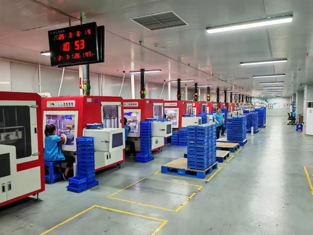
Continuous R&D investment in energy-efficient motor technologies
Lean manufacturing processes ensuring cost-competitive pricing
Agile production capacity scaling for batch customization
Global compliance certifications (CE, RoHS, REACH)
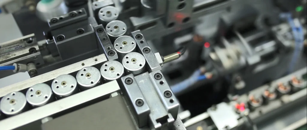
With dual focus on operational excellence and client success, Twin Motor empowers businesses worldwide to achieve technological differentiation. Our engineering team welcomes complex challenges across automotive, robotics, and smart infrastructure applications.
Contact our solutions center to discuss your project requirements or request our technical portfolio.
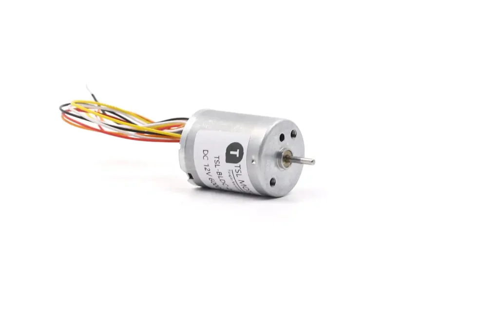
Brushless DC Motor
Brushless DC motors provide a solution to meet the demands for higher energy efficiency, longer lifespan, and quieter operation. As a leading manufacturer of BLDC motors,TSL Motors has developed the smallest BLDC motor, measuring just 6mm in diameter and 2mm in thickness, designed as a flat vibration motor.