Published: NOVEMBER 17, 2025
Updated:SEPTEMBER 1, 2026
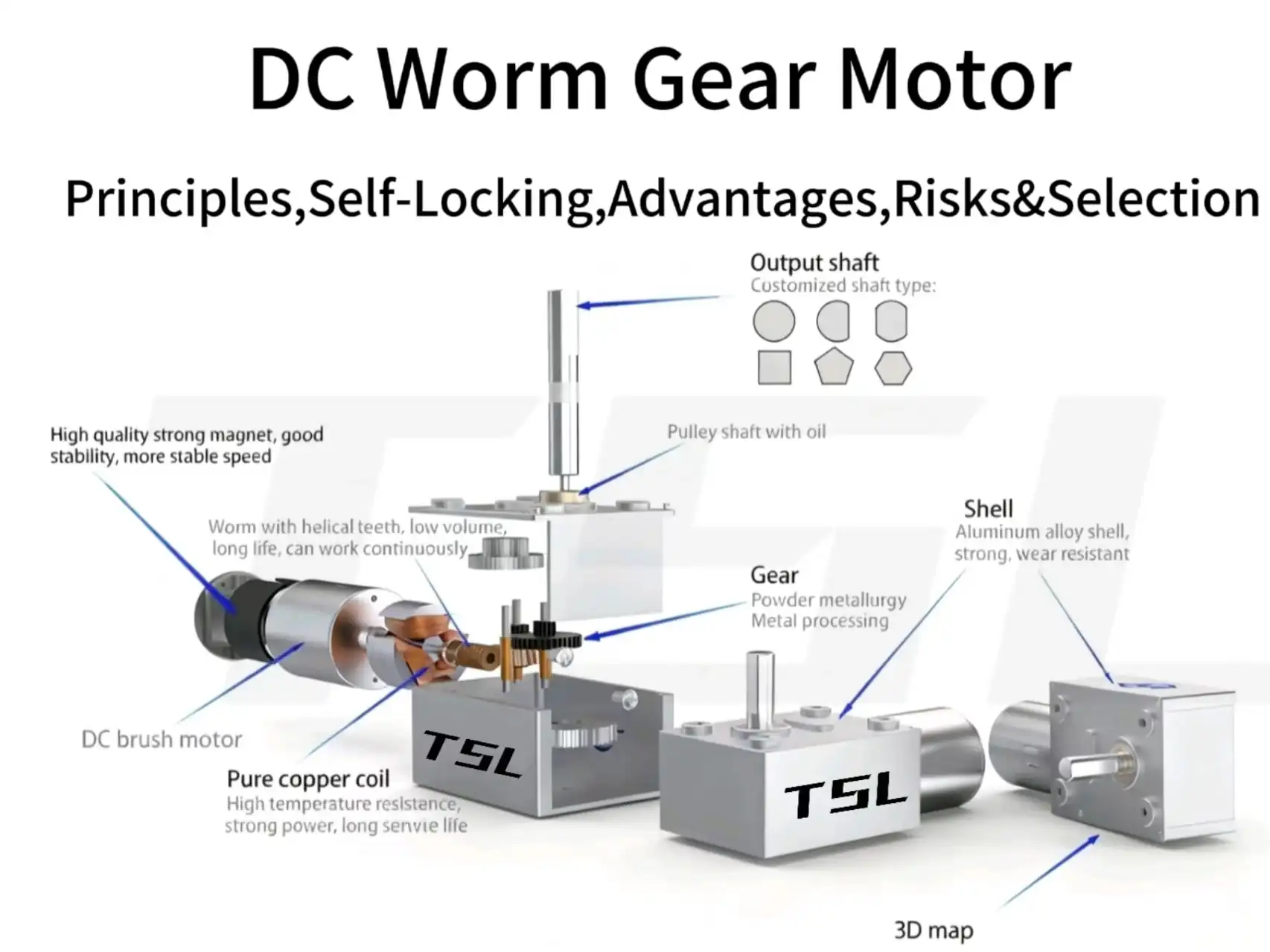
A DC worm gear motor combines a DC motor with a worm gearbox to produce low-speed, high-ratio output in a right-angle layout. It is often a practical starting point when an application also needs resistance to back-driving after power is removed.
From an engineering point of view, the difficult question is not whether a worm gearbox can reduce speed and increase torque. It is whether the selected unit can deliver the required continuous torque without excessive temperature rise—and whether it will actually hold the load under real operating conditions. Neither answer can be determined from the reduction ratio alone.
Self-locking depends on worm geometry, tooth friction, gear materials, lubrication, temperature, wear and manufacturing tolerances. A gearbox that holds during a static bench test may still creep or back-drive when exposed to vibration, shock or long-term wear.
This guide explains how a DC worm gear motor works, when self-locking may occur, why it can fail and how to evaluate ratio, torque, duty cycle, efficiency, mounting and back-driving before selection.
Key Takeaways
- A DC worm gear motor provides a right-angle output and can achieve a large speed reduction within a compact transmission layout.
- Some worm gearboxes resist back-driving, but not every worm gear motor is self-locking. A high reduction ratio alone does not guarantee that the output will hold its position.
- The theoretical tendency toward self-locking depends mainly on the relationship between the worm lead angle and the friction angle of the meshing surfaces.
- Actual holding behavior can change with gear materials, lubrication, temperature, wear, manufacturing tolerances, vibration and shock.
- Stronger resistance to back-driving usually comes with lower transmission efficiency and greater heat generation during operation.
- Selection should be based on loaded output speed, rated continuous torque, peak-load duration, duty cycle, allowable temperature rise and the required level of back-driving resistance.
- Self-locking must not be treated as an independent safety brake. Use a separate brake or locking device wherever unintended movement could cause injury or equipment damage.
DC Worm Gear Motor Construction, Working Principle, and Self-Locking
Understanding the basic transmission path makes it easier to evaluate reduction ratio, output torque and back-driving behavior.
What is a DC worm gear motor?
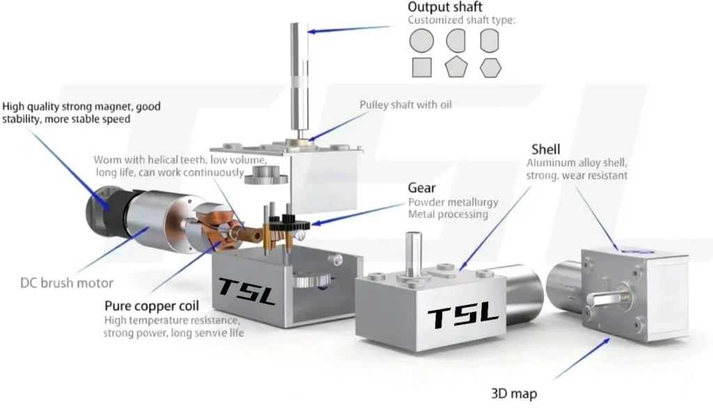
A DC worm gear motor integrates two functional assemblies:
- DC motor: A brushed or brushless motor that provides the input speed and torque.
- Worm gearbox: A worm-and-wheel reduction stage that reduces speed, redirects the output and increases the available output torque.
The motor, gearbox and load must be evaluated as one system. A gearbox may provide a large reduction ratio, but its usable output remains limited by efficiency, temperature rise and the rated mechanical capacity of the gears, shafts, bearings and housing.
How a DC worm gear motor works
The mechanical structure of the worm gear system is the root of all its characteristics. The system consists of two key components:
- Worm: A threaded screw (usually the active part), connected to the motor’s output shaft .
- Worm Wheel: A gear that meshes with the worm (usually the driven part) .
The motor rotates the worm, whose helical tooth surface slides against the teeth of the worm wheel. This contact advances the wheel and turns the output shaft, which is normally positioned at 90° to the motor shaft.
For a basic single-stage worm pair, the reduction ratio can be estimated as:
Reduction ratio = Number of worm-wheel teeth ÷ Number of worm starts
A 40-tooth worm wheel driven by a single-start worm therefore has a theoretical ratio of 40:1. A two-start worm driving the same wheel produces a ratio of 20:1.
The approximate output torque is:
Output torque ≈ Motor torque × Reduction ratio × Gearbox efficiency
This is only a calculation estimate. The permissible continuous output torque must still remain below the gearbox’s rated mechanical limit.
For more detail on worm-and-wheel geometry, materials and internal transmission design, see our worm gearbox working principle and design guide.
When Can a DC Worm Gear Motor Resist Back-Driving?
Self-locking describes a condition in which torque applied to the worm-wheel side cannot rotate the worm and drive the motor backward. It should not be confused with motor holding torque, an energized holding current or a separate mechanical brake.
In practice, back-driving behavior is not always a simple yes-or-no characteristic. One gearbox may resist movement but still creep slowly under load, while another may remain stationary under the same static test conditions.
Theoretical Self-Locking Condition: Lead Angle vs. Friction Angle
A simplified static assessment compares the worm lead angle with the friction angle of the meshing surfaces:
γ < φ
The same condition can be expressed as:
tan γ < μ
Where:
- γ is the worm lead angle;
- φ is the friction angle;
- μ is the effective coefficient of friction between the worm and worm-wheel tooth surfaces;
- φ = arctan μ.
When the lead angle is lower than the effective friction angle, load-side torque may be unable to overcome tooth-contact friction and rotate the worm. This indicates a theoretical tendency toward static self-locking.
However, the coefficient of friction is not a fixed gearbox value. It changes with gear materials, lubricant, surface finish, contact pressure, sliding speed, temperature and wear. A gearbox that holds when cold or lightly lubricated may behave differently after warming up or completing many operating cycles.
The number of worm starts and the reduction ratio influence the lead angle, but neither value independently proves that a gearbox is self-locking.
The AGMA technical paper on self-locking gears also identifies low efficiency and increased heat generation as important limitations of conventional self-locking worm drives.
How to Design for High Self-Locking Capability?
Self-locking tendency is governed mainly by the worm lead angle and the effective friction between the tooth surfaces. The number of starts also matters because, for the same basic worm geometry, adding more starts usually increases the lead angle and makes back-driving easier:
| Worm Type | Lead Angle (γ) | Reduction Ratio | Self-locking Capability |
| Single-start worm | Small (≤ 5–6°) | High (40:1, 60:1, even 100:1) | Strong (Easily achieves self-locking) |
| Multi-start worm | Large (≥ 10°) | Low (10:1, 20:1) | Weak/None (Difficult to achieve self-locking) |
Conclusion: If the application requires absolute self-locking (like lifting platforms, medical beds), priority should be given to high-reduction-ratio, single-start worms. Their lead angle is smaller, making it easier to meet the self-locking condition.
The Key Engineering Trade-off: Self-Locking vs. Efficiency
Self-locking is a double-edged sword. Engineers must understand the accompanying compromise:
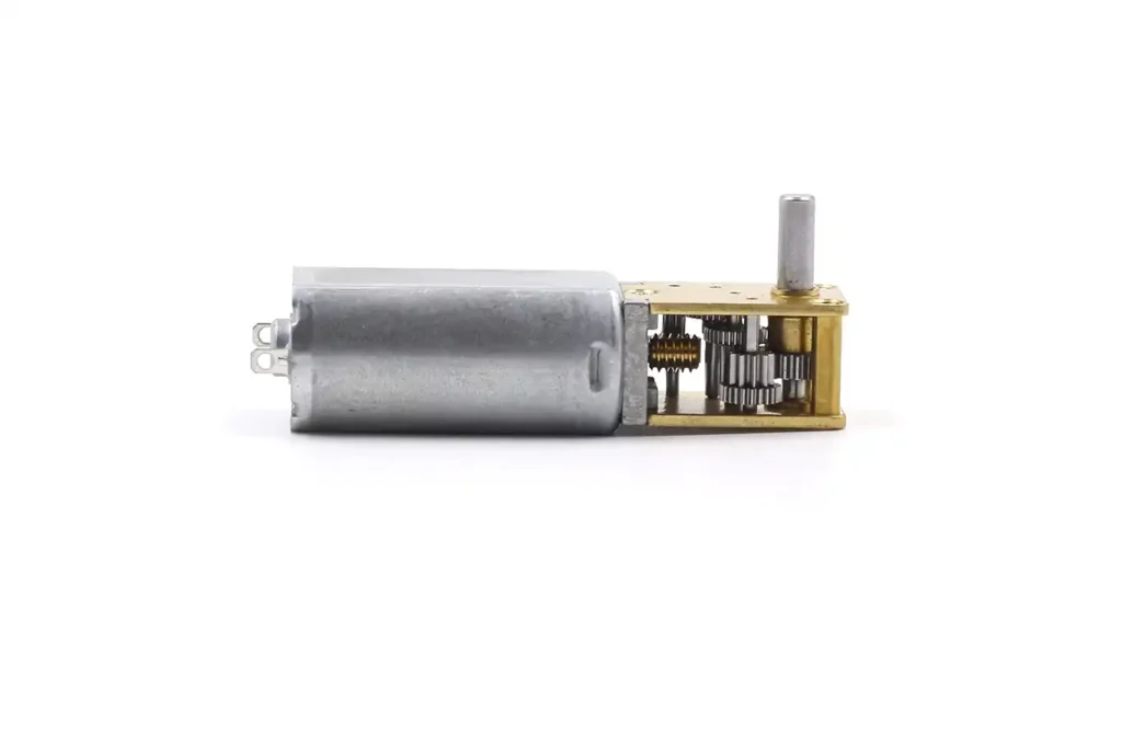
A stronger tendency to resist back-driving generally requires a smaller lead angle and greater frictional resistance at the tooth contact. The same sliding friction that opposes reverse motion also consumes energy during forward operation and converts part of the input power into heat.
- Smaller lead angles and single-start worms generally provide greater resistance to back-driving, but they also tend to produce lower efficiency and more heat.
- Larger lead angles and multi-start worms can improve forward-driving efficiency, but they are normally easier to back-drive.
- Gearbox efficiency is an operating-point value. It changes with ratio, load, input speed, lubrication, temperature, materials and manufacturing quality.
Fixed efficiency ranges should therefore not be assigned from the lead angle or number of starts alone. Actual efficiency and temperature rise should be confirmed using data measured at the intended speed, load and duty cycle.
Manufacturer’s Risk Advisory: Self-Locking Is Not a Safety Brake
Although resistance to back-driving can be useful, worm-gear self-locking should not be treated as a guaranteed safety function:
- Vibration and Shock: External vibration, impact or fluctuating load can disturb the static tooth contact and initiate small movements. Once movement begins, the gearbox may creep or back-drive even if it held the same load during a stationary bench test.
- Changing Operating Conditions: Effective friction can change with lubrication, temperature, wear, surface condition and sliding speed. A gearbox should therefore be tested under the actual load and environmental conditions rather than classified as self-locking from the calculated lead angle alone.
Critical Advice: Where unintended movement could injure people or damage valuable equipment, use an independent brake or mechanical locking device and verify compliance with the safety requirements applicable to the complete machine. Holding tests should include maximum load, temperature extremes, vibration, shock and representative wear cycles.
For example, OSHA 1910.179 requires each independent crane hoisting unit to have at least one holding brake. Its worm-geared exception concerns the additional control-braking requirement, not the primary holding brake.
DC Worm Gear Motor:Unique Advantages
Compared with planetary and spur gear motors, the main advantages of a worm gear motor are its right-angle shaft arrangement, the ability to obtain a relatively high reduction ratio in one stage and, in suitable designs, resistance to back-driving.
Sliding tooth contact also influences noise, efficiency and heat generation, so it should be understood as an engineering trade-off rather than the source of every advantage.
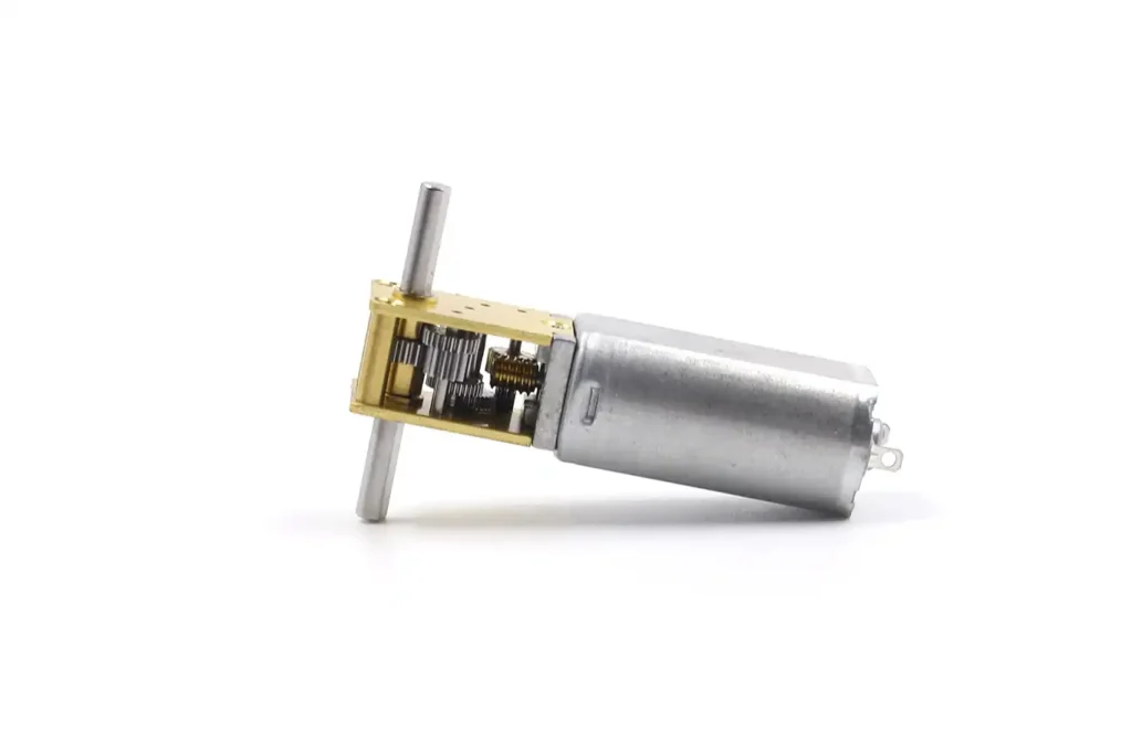
High Reduction Ratio and Torque Multiplication
As output speed decreases, the theoretical torque multiplication increases with the reduction ratio. Actual output torque can be estimated as:
Output torque ≈ Motor torque × Reduction ratio × Gearbox efficiency
The usable output torque must still remain below the rated mechanical limit of the gearbox. A worm drive can therefore provide useful torque multiplication in a compact right-angle arrangement, but it does not automatically produce more torque or higher torque density than a planetary or spur gearbox. Planetary gearboxes, in particular, often provide higher torque density and efficiency.
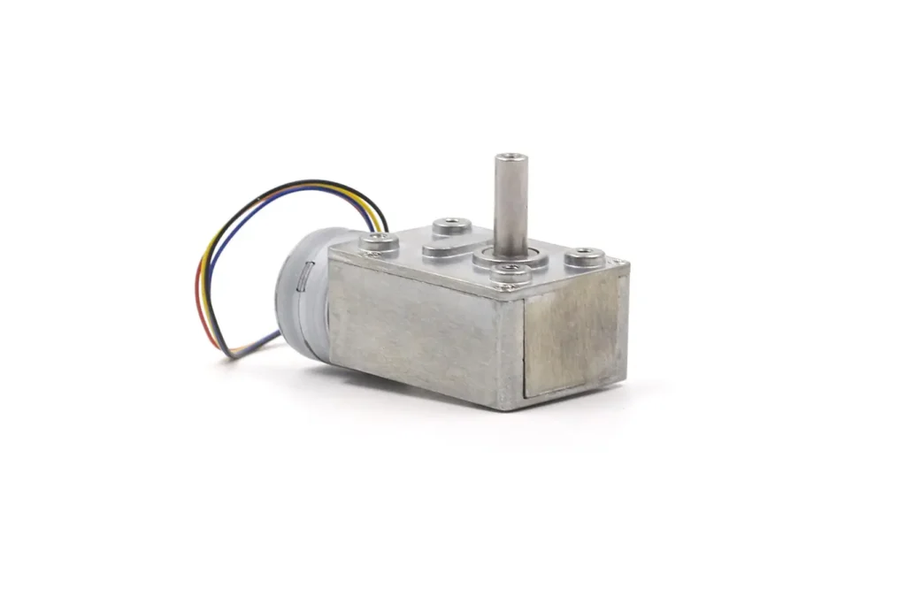
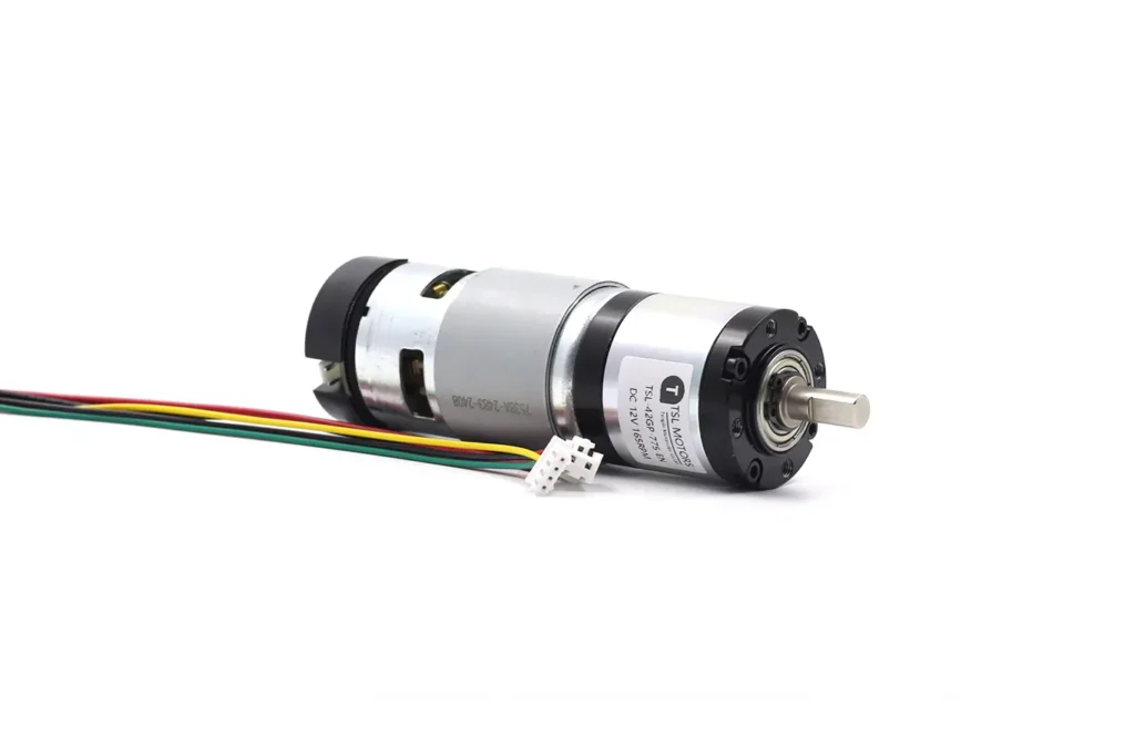
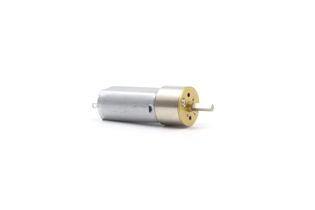
Application Value: This arrangement is useful when the application requires low output speed, a right-angle layout and substantial torque multiplication within a limited axial length. For heavy-load starting or high-inertia loads, verify the motor’s starting current, available motor torque, gearbox peak-torque rating and permitted peak duration.
Self-Locking and Resistance to Back-Driving
Resistance to back-driving is an important reason for considering a worm gear motor instead of a conventional planetary or spur gear motor. When the worm geometry and friction conditions are suitable, the gearbox may resist external torque applied at the output after power is removed.
However, not every worm drive is self-locking, and actual holding performance must be verified under the intended load and operating conditions.
| Ratio | No Load | Rated Load | Stall | ||||||
| i:1 | Voltage | Speed | Current | Speed | Current | Torque | Power | Torque | Current |
| V | PRM | A | PRM | A | Kg.cm | W | Kg.cm | A | |
| 6.25 | 12 | 960 | 0.12 | 685 | 0.9 | 0.94 | 15.0 | 4 | 6.5 |
| 10 | 12 | 600 | 0.12 | 428 | 0.9 | 1.50 | 15.0 | 4.8 | 6.5 |
| 18.8 | 12 | 319 | 0.12 | 228 | 0.9 | 2.82 | 15.0 | 6 | 6.5 |
| 30 | 12 | 200 | 0.12 | 142 | 0.9 | 4.50 | 15.0 | 18 | 6.5 |
| 56 | 12 | 107 | 0.13 | 76 | 0.9 | 8.40 | 15.0 | 32 | 6.5 |
| 90 | 12 | 66 | 0.13 | 50 | 0.9 | 13.50 | 15.0 | 52 | 6.5 |
| 131 | 12 | 45 | 0.13 | 32 | 0.9 | 19.65 | 15.0 | 76 | 6.5 |
| 169 | 12 | 35 | 0.13 | 25 | 0.9 | 25.35 | 15.0 | 87.5 | 6.5 |
| 270 | 12 | 22 | 0.13 | 16 | 0.9 | 40.50 | 15.0 | 141 | 6.5 |
| 506 | 12 | 11 | 0.13 | 9 | 0.9 | 60.00 | 15.0 | 180 | 6.5 |
| 810 | 12 | 7 | 0.13 | 8 | 0.9 | 60.00 | 15.0 | 180 | 6.5 |
The table shows the no-load, rated-load and stall performance of a specific motor-and-gearbox configuration. Stall torque and stall current are short-duration limits—not continuous operating ratings or proof of self-locking. Use the rated-load column for initial continuous-duty screening, then verify temperature rise and power-off holding separately.
Compact Right-Angle Design: Optimizing Equipment Layout
The mechanical structure of the worm and wheel dictates that their input (motor) and output (wheel) shafts are inherently at a 90-degree right angle.
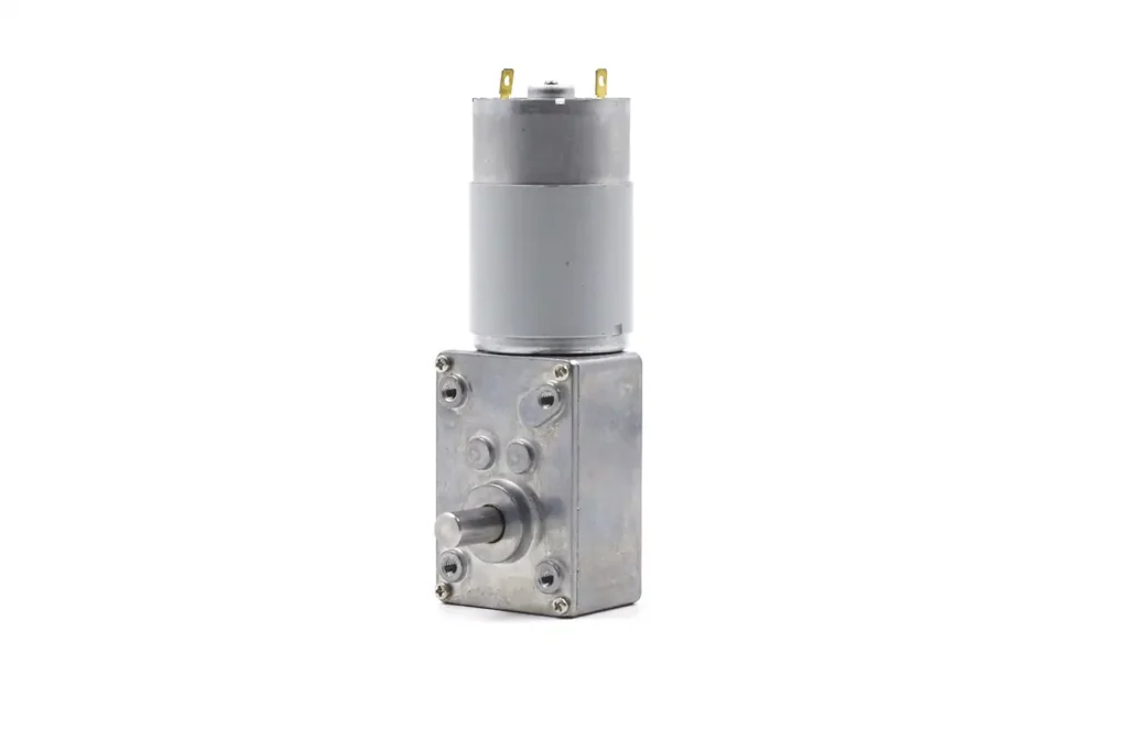
Application Value: The right-angle configuration allows the motor body to lie parallel to a mounting surface while the output shaft drives a perpendicular load. This can reduce the required axial installation length compared with an inline gearbox, although it does not necessarily reduce the total occupied volume.
For example, in a conveyor system, the motor can be mounted along the side frame instead of projecting outward from the driven roller axis. In automatic doors and smart-home mechanisms, the same layout can help the drive fit inside a shallow enclosure.
Before confirming the design, check the required output-shaft side and rotation direction, shaft length, mounting-hole position, connector and cable clearance, housing envelope and access for assembly. The mounting structure must also withstand gearbox reaction torque and any radial or axial load applied to the output shaft.
Low Noise and Smooth Operation
The transmission method of worm gears is fundamentally different from other gears. Spur gears may produce more noticeable tooth-meshing noise in some designs, but actual noise depends on gear accuracy, backlash, speed, load, lubrication, housing and mounting conditions.
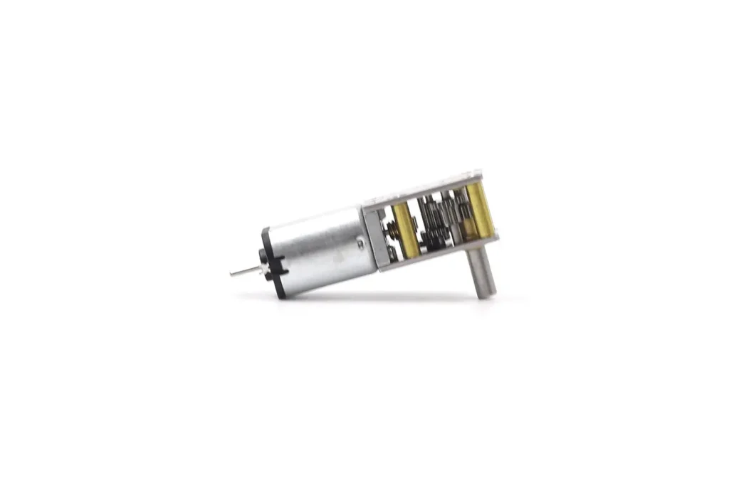
However, worm gear transmission is a “sliding action” of the worm thread across the worm wheel teeth. This sliding contact can support smoother low-speed motion, but it does not guarantee lower total drive noise because the motor, bearings and housing may remain important noise sources.
Application Value:
While this sliding causes efficiency loss (as mentioned), in many applications, quietness is a more important parameter than efficiency. This makes worm gear motors one option to evaluate for medical equipment, adjustable furniture, smart-home mechanisms and AV equipment where smooth low-speed operation is important. If noise is a critical requirement, compare candidate drives under the intended speed, load and mounting conditions.
To help engineers weigh the trade-offs, the table below compares three mainstream DC gear motor solutions. It clearly shows that the DC worm gear motor is a solution born for specific working conditions.
Table 1: Comparison of Mainstream DC Gear Motor Technologies
| Feature | Worm Gear Motor | Planetary Gear Motor | Spur Gear Motor |
| Output Shaft | 90-Degree | In-line | In-line |
| Torque Density | Very High | High | Medium |
| Efficiency | Low to Medium (Often <60%) | High (Approx. 90%+) | Very High (Approx. 95%+) |
| Self-Locking | Yes | No | No |
| Noise | Very Low | Medium | High |
| Compactness | Very High | High | Medium |
DC Worm Gear Motor:Applications
The unique combination of advantages of DC worm gear motors makes them indispensable components in the following five major fields.
Precision Smart Locks & Security Modules
Examples:
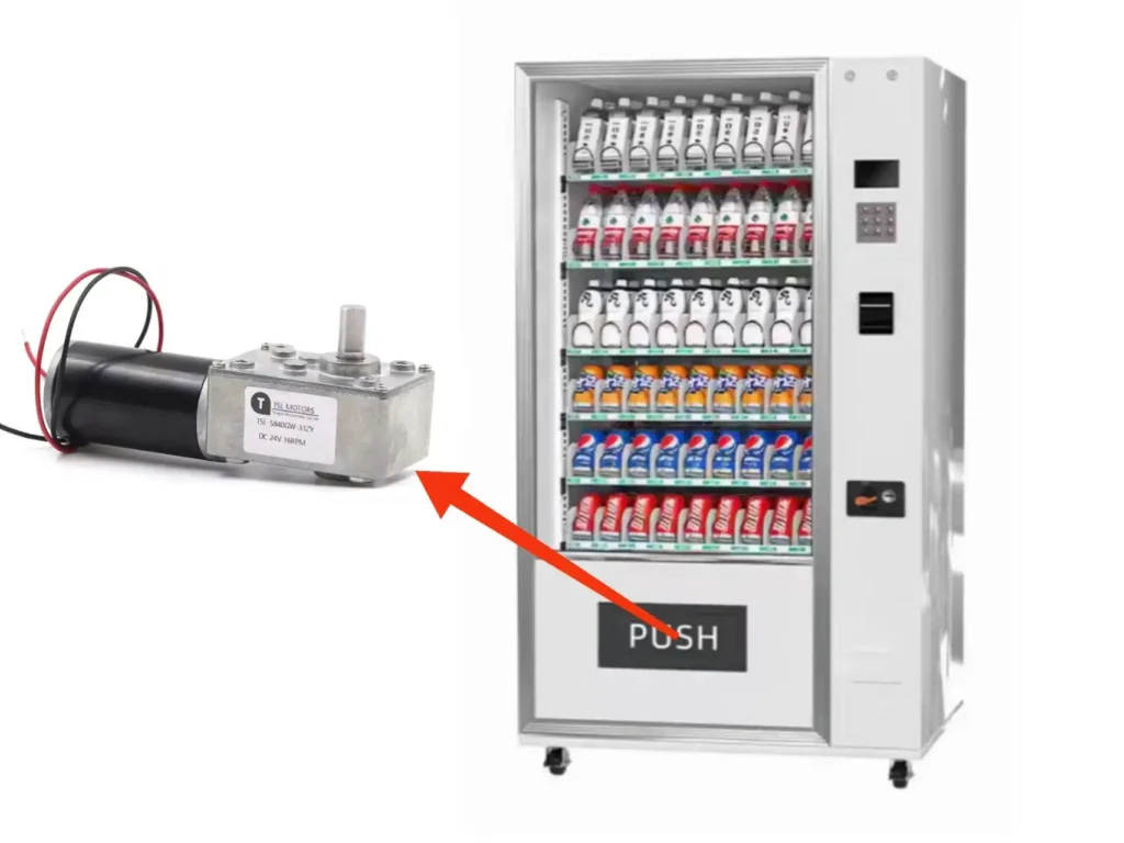
Electronic smart door locks, safe locks, cabinet locks, vending machine lock actuators.
Pain Point:
Small locks require powerful torque in a very compact space, plus absolute self-locking to avoid forced opening.
Why Micro Worm Gear Motor:
- Extremely compact
- Self-locking prevents mechanical back-driving
- High torque per volume
Solution:
The motor drives the lock mechanism, and when power is removed, the worm reducer itself becomes the lock, preventing prying or forced rotation. No extra solenoid or brake is needed.
Mini Robotics & Consumer Robots
Examples:
Robotic fingers, micro grippers, humanoid robot joints, desktop cobots.
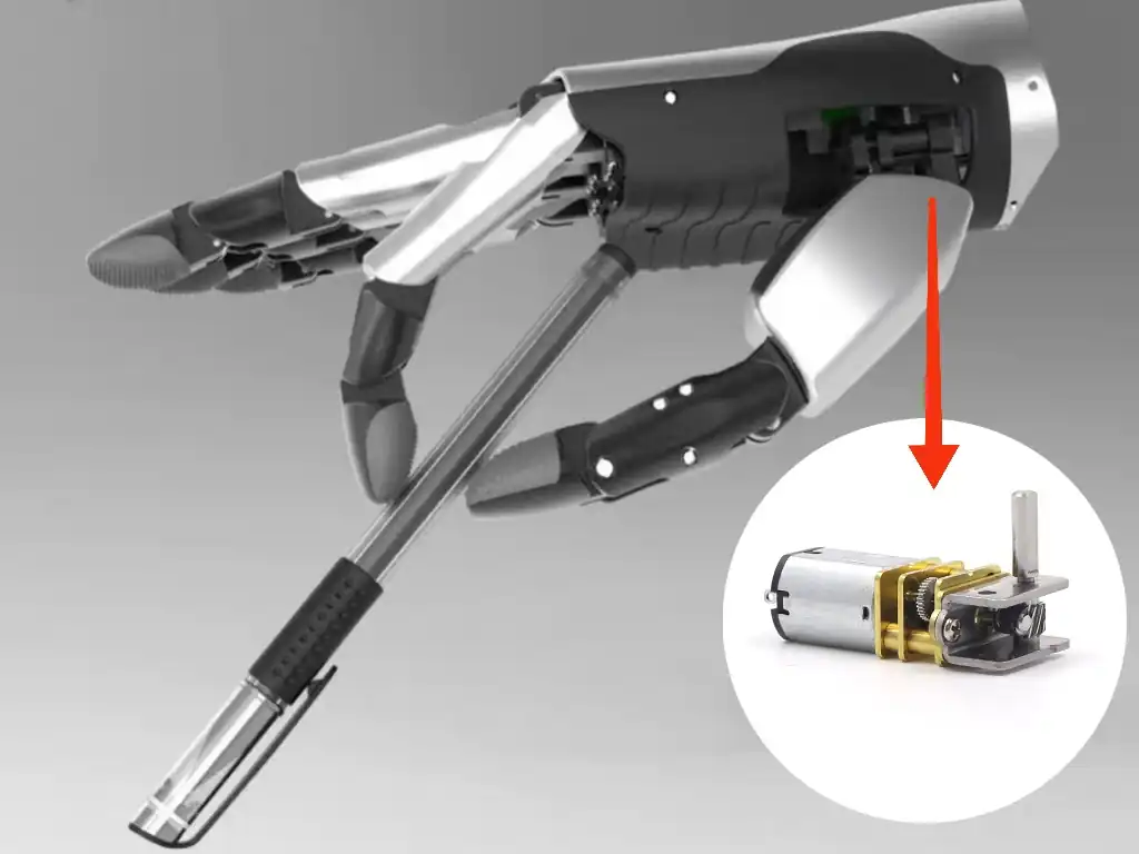
Pain Point:
Robotic joints need high torque, low speed, stable holding force, and ultra small size.
Why Micro Worm Gear Motor:
- High torque density
- Right-angle structure simplifies joint packaging
- Self-locking allows robots to hold without consuming power
Solution:
A finger or mini arm can hold an object in position with zero power, reducing heat and battery consumption.
Portable Medical & Healthcare Devices
Examples:
Insulin injector drive, portable infusion pumps, handheld surgical devices, compact patient assist equipment.
Pain Point:
Portable medical devices require very low noise, compact size, and absolute position stability (no drifting under load).
Why Micro Worm Gear Motor:
- Extremely quiet sliding transmission
- Precise controlled motion
- Self-locking prevents accidental release or motion during power loss
Solution:
The worm gearbox keeps the mechanism fixed even if battery is removed—critical for safety.
Camera / Optical Mechanisms & Precision Adjustments
Examples:
CCTV PTZ control, micro gimbals, laser alignment modules, telescope focus mechanisms.
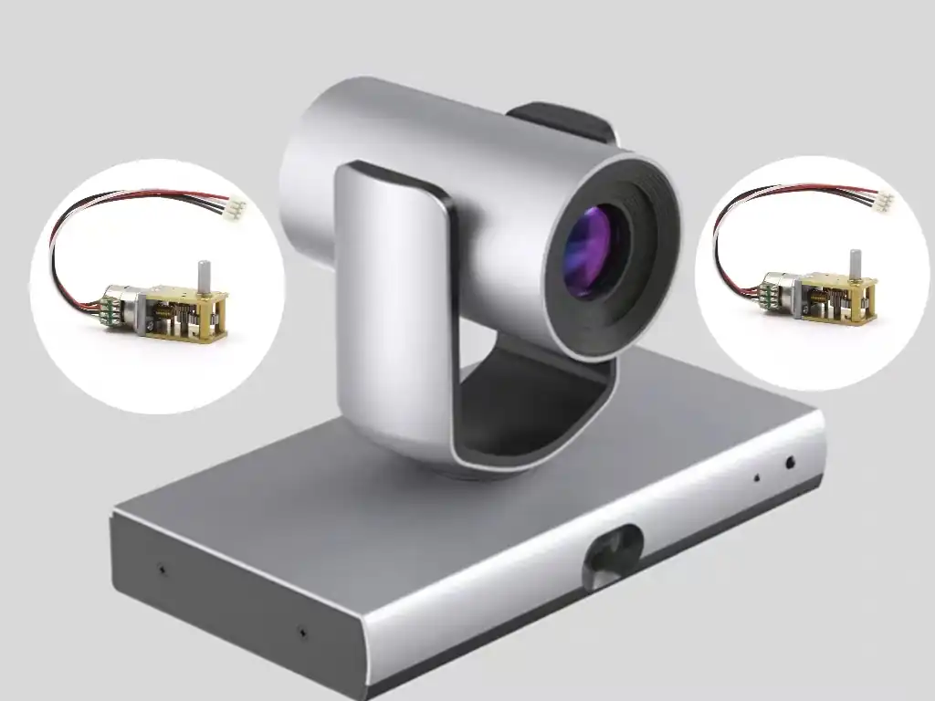
Pain Point:
Optical positioning requires slow, ultra-fine movement and zero backlash drifting.
Why Micro Worm Gear Motor:
- Small footprint suits high-density optical housings
- Smooth motion with high reduction ratio
- Worm self-lock maintains angle without continuous current
Solution:
Motor only runs during adjustment; after positioning, the system stays locked without power, improving stability and battery life.
Compact Consumer Mechatronic Devices
Examples:
Smartphone lens actuators, motorized perfume sprayers, micro vending mechanisms, miniature valves, compact folding structures.
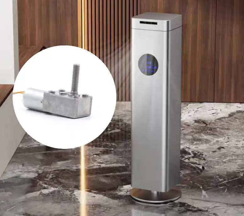
Pain Point:
Limited installation space, lightweight design, smooth and silent motion required.
Why Micro Worm Gear Motor:
- Option to fit inside 8–20 mm device thickness
- Quiet transmission
- Built-in torque output sufficient for small actuation tasks
Solution:
Allows motorized transformation, folding, ejecting, lifting in extremely compact designs without adding noise or mechanical brakes.
Manufacturer’s Selection Guide: 5 Key Parameters You Must Consider
As a DC worm gear motor manufacturer, our discussions with customers always focus on the following 5 parameters.
TSL-5840GW-3650BL-1240, 12V DC
| Ratio | No Load | Rated Load | Stall | ||||||
| Voltage | Speed | Current | Speed | Current | Torque | Power | Torque | Current | |
| i:1 | V | RPM | A | RPM | A | Kg.cm | W | Kg.cm | A |
| 17 | 12 | 235 | 0.15 | 180 | 0.4 | 1.3 | 2.45 | 4.3 | 1.2 |
| 31 | 12 | 130 | 0.15 | 100 | 0.4 | 2.4 | 2.51 | 8 | 1.2 |
| 50 | 12 | 80 | 0.15 | 60 | 0.4 | 4 | 2.51 | 12.5 | 1.2 |
| 100 | 12 | 40 | 0.15 | 30 | 0.4 | 8 | 2.51 | 25 | 1.2 |
| 200 | 12 | 20 | 0.15 | 15 | 0.4 | 16 | 2.51 | 51 | 1.2 |
| 290 | 12 | 14 | 0.15 | 10 | 0.4 | 23.2 | 2.43 | 70 | 1.2 |
| 500 | 12 | 8 | 0.15 | 6 | 0.4 | 37.5 | 2.36 | 70 | 1.2 |
| 670 | 12 | 6 | 0.15 | 4 | 0.4 | 50 | 2.09 | 70 | 1.2 |
Parameter 1: Rated Torque and Speed
Torque and Speed are the cornerstones of selection, and they are inversely related. While the gearbox reduces speed, it (ignoring efficiency losses) multiplies torque. Your first task is to precisely define the final output torque and speed required by the application.
Manufacturer’s Insight (Key Pitfall): The most common mistake engineers make during selection is confusing three different types of torque.
- Running Torque: The torque required for the application to run at a constant speed. This is the basis for calculating S1 continuous duty.
- Peak/Acceleration Torque: The extra torque needed to overcome load inertia when starting the system from rest.
- Stall Torque: The maximum torque the motor can output at zero speed, e.g., to “break free” from static friction.
Selection Guide: The motor’s “Rated Torque” must be greater than the application’s “Running Torque.” The motor’s “Stall Torque” (or Peak Torque) must be greater than the “Peak Torque” required for application startup or acceleration. In all calculations, we strongly recommend adding a 20-30% Safety Margin.
Parameter 2: Gear Ratio
The gear ratio defines how many turns the motor (input) makes for the gearbox (output) to turn once.
How to choose the gear ratio?
- The formula is very direct: Gear Ratio = Motor Input Speed (RPM) / Required Load Output Speed (RPM) 18.
Calculation Example: Your DC motor’s efficient speed at rated voltage is 3000 RPM. Your conveyor belt design needs to run at 50 RPM.
- Required Gear Ratio = 3000 RPM / 50 RPM = 60:1.
Parameter 3: Self-Locking Requirement
Do not assume all worm gear motors have strong self-locking.
Clarify the need
Does your application must have self-locking? Is it “nice-to-have” or “mission-critical”?
Technical Implication
The self-locking capability is directly related to the worm’s lead angle (λ\lambda). If you need “absolutely reliable” self-locking, you may need a single-start worm with an extremely small lead angle.
Professional Advice
Please clearly state your self-locking requirements when making an inquiry. This will influence the type of worm our engineers recommend and is directly related to the motor’s final efficiency and cost.
Parameter 4: Duty Cycle (Continuous S1 vs. Intermittent S3)
The biggest enemy of a DC motor is heat. Overheating can burn winding insulation, cause gearbox grease to fail, and even permanently demagnetize the magnets, leading to complete motor failure. The key factor determining heat accumulation is the duty cycle.
Define your duty cycle (IEC International Standards):
S1 – Continuous Duty: The motor runs under a constant load for long enough to reach thermal stability (heating power = cooling power).
Typical Applications: Industrial conveyors, ventilation fans.
S2 – Short-time Duty: The motor runs at a constant load for a specific short time (e.g., S2 30min), followed by a rest period long enough to cool to ambient temperature.
Typical Applications: Emergency winches, backup pumps.
S3 – Intermittent Periodic Duty: The motor performs a series of identical “run-stop” cycles. The key is that the stop time is not sufficient for the motor to cool completely. Often expressed as a percentage, e.g., “S3 25%” (e.g., 15 seconds run, 45 seconds stop).
Typical Applications: Robotic joints, automatic doors, medical actuators.
Manufacturer’s Insight (Huge Cost Savings): This is one of our most important conversations with clients. Many engineers over-specify.
Incorrect Scenario: Customer A says: “I need a motor that provides 10 N·m of torque.”
Traditional Selection: An unprofessional supplier provides a motor rated for S1 (continuous) 10 N·m. This motor must be very large, heavy, and expensive because it’s designed to continuously dissipate the heat generated by a 10 N·m load.
Professional Consultation: We ask: “What is your duty cycle?” Customer A replies: “I only need it to output 10 N·m for 5 seconds to close a gate, once per minute.”
Correct Selection: This is a typical S3 duty cycle (5 sec run, 55 sec stop). We can select a much smaller, less expensive motor. This motor (e.g., with an S1 rating of only 3 N·m) is fully capable of outputting 10 N·m of peak torque for a short time because it has 55 seconds to cool down.
Understanding your duty cycle can significantly save you cost and installation space without sacrificing performance.
Parameter 5: Dimensions, Mounting & Physical Integration
No matter how perfect the motor’s performance, it’s all useless if it cannot be installed in your equipment.
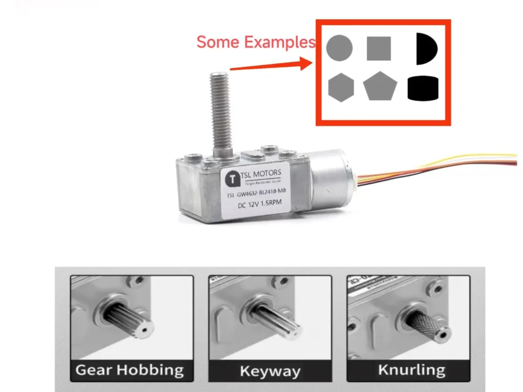
Key Dimensional Parameters:
- Mounting Interface (Flange/Foot):
- Foot-Mount: The motor has “feet” and is bolted to a mounting base (e.g., IEC B3).
- Flange-Mount: The motor has a machined mounting face on the front, bolting directly to the equipment frame. This is common in NEMA (e.g., C-Face, D-Flange) and IEC (e.g., B5, B14) standards. Flange mounting requires high coaxial alignment.
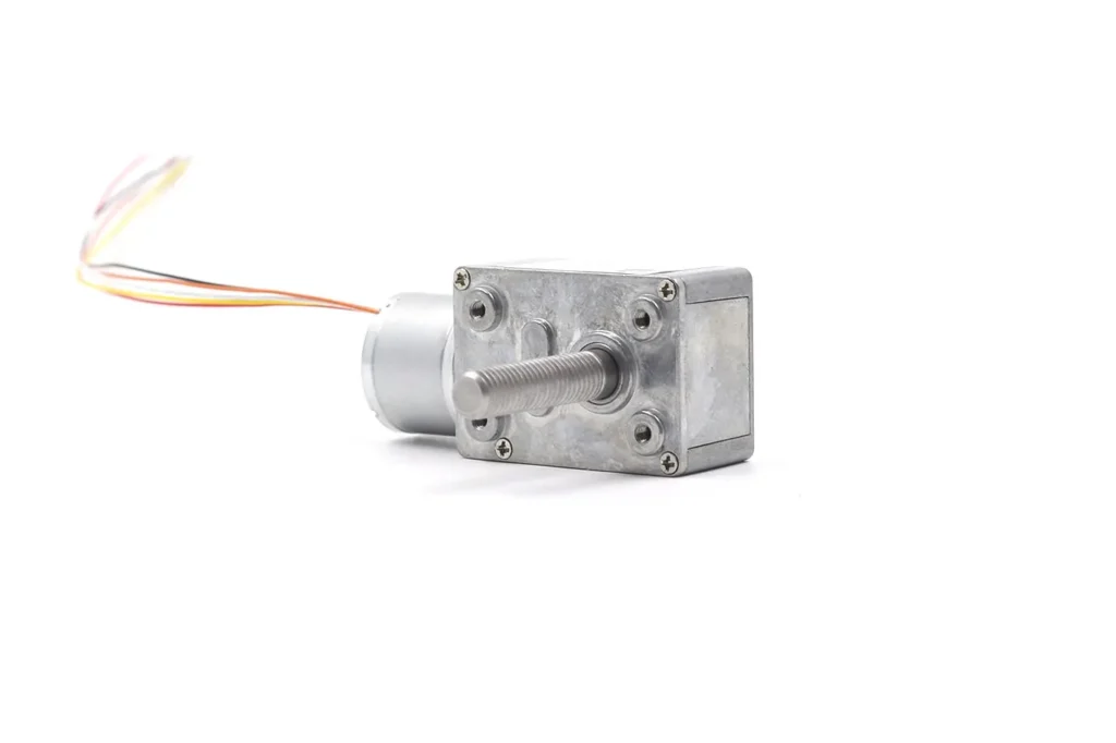
- Output Shaft: This is the key power transmission interface. You must confirm:
- Shaft diameter and length.
- Shaft type: Does it have a Keyway? A D-cut? Or a threaded shaft?. The wrong shaft type will not connect to your load.
Manufacturer’s Insight (Our Core Advantage): This is the end of the road for standard “off-the-shelf” suppliers, but it’s where we begin as a manufacturing partner.
- Your Dilemma: The bolt holes on your equipment are special, and a standard NEMA 56 C-Face 45 won’t fit. You need an 8mm D-cut shaft, but all standard options are 10mm keyway shafts.
- Our Solution (Customization): As a true manufacturer, we are not bound by “standard products.” We offer comprehensive engineering customization services:
- Custom output shafts (length, diameter, D-cut, keyway, material).
- Custom mounting flanges (to match your special bolt hole pattern).
- Custom electrical characteristics (e.g., non-standard 18V voltage instead of 12V/24V).
- Special grease (for high or low-temperature environments).
This is the greatest value of working with a manufacturer (not a distributor).
Conclusion
Choosing the right DC worm gear motor is not a simple purchase; it is a rigorous engineering analysis.
There is no “best” choice, only the “most suitable” choice. A successful integration depends on your precise analysis of the 5 key parameters: Torque, Gear Ratio, Self-Locking Requirement, Duty Cycle, and Physical Mounting.
Standard product catalogs are just a starting point. As your manufacturing partner, our true value lies in solving challenges that standard solutions cannot meet.
Our engineering team is an extension of your design team, ready to intervene when a standard product is only “almost” right.
From custom output shafts and non-standard mounting flanges 5 to motor windings that match your special power supply, we will ensure you receive a performance-optimized, perfectly matched, customized solution.
Your Next Steps
- Explore: Now that you have the technical knowledge to specify a solution, visit our dc worm gear motor to browse our standard product lines.
- Verify: Need to check specific dimensions, download CAD models, or performance curves? Please dive into our Detailed Spec Page for datasheets and engineering drawings.
- Partner: Does your design face a unique challenge? Standard products don’t meet your needs? Don’t compromise. Contact our application engineers today to discuss your project, and let us build a custom solution for you.
FAQ
Q1: What are its biggest features?
A1: Three things: 1) 90-degree right-angle output (saves space); 2) Self-locking (can hold a load when unpowered); 3) Extremely quiet (uses sliding, not impact, gears).
Q2:Can “self-locking” replace a safety brake?
A2: Absolutely not. Self-locking can fail under vibration or shock. For any application involving human safety, you must add a separate, independent brake.
Q3:What is the “cost” of self-locking?
A3: Low efficiency. The same high friction that creates the lock also wastes energy (as heat) when the motor is running. Its efficiency is much lower than a planetary gearbox.
Q4:What is the biggest “money-saving” tip for selection?
A: Understand your “Duty Cycle.” Don’t buy an expensive “Continuous Duty” (S1) motor for an “Intermittent” (S3) job (e.g., run 5 sec, stop 45 sec). An S3-rated motor can output huge peak torque for short bursts using a much smaller, cheaper frame, as it has time to cool down.
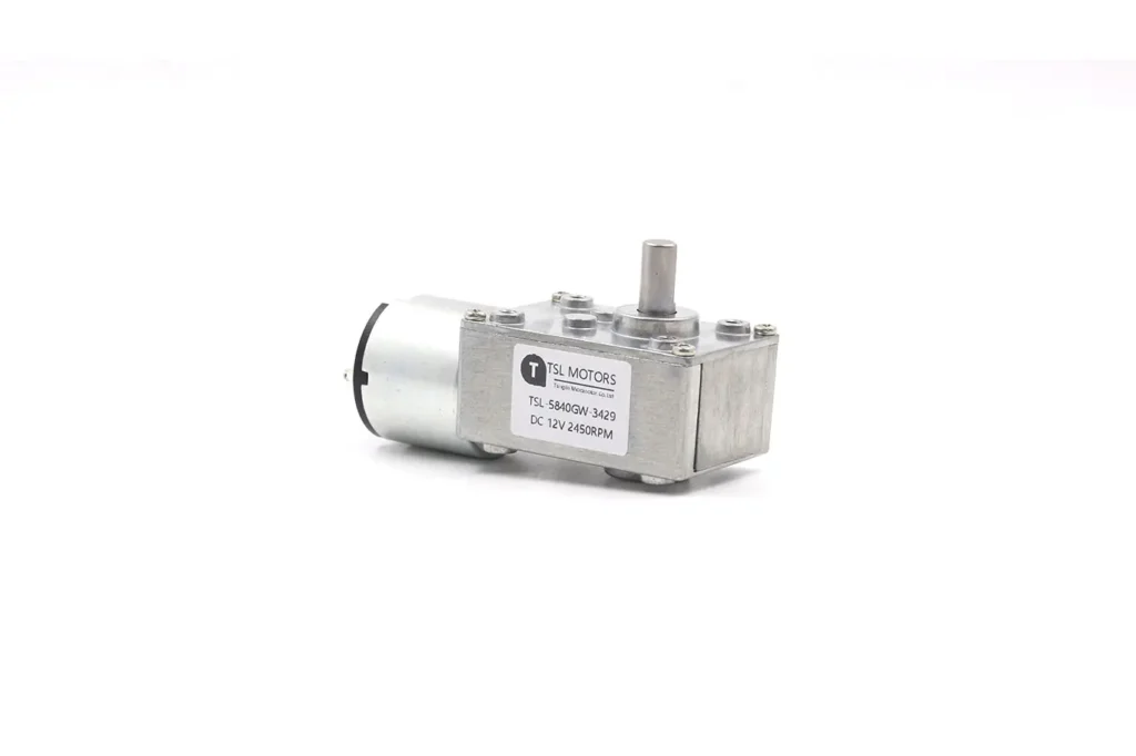
Worm Gear Motor
TSL Motors is a leading manufacturer specializing in custom worm gear motors, offering dependable solutions tailored to meet the specific needs of various applications. With our in-depth knowledge of DC worm gear motors and gear technology, we assist OEMs in developing, identifying, and implementing innovative geared motor solutions with greater speed. These compact, quiet, self-locking motors, also capable of static damping, provide exceptional torque density.