Published: DECEMBER 18, 2025
Updated:SEPTEMBER 28, 2026
A worm gearbox is usually selected not because it is the most efficient gearbox, but because it can combine a large reduction ratio, a compact right-angle layout and useful resistance to back-driving. These characteristics make it practical for compact actuators, positioning mechanisms and equipment that must resist load movement after the drive stops.
Actual performance depends on worm geometry, materials, lubrication, load, temperature and manufacturing accuracy. Based on TSL Motor’s experience in micro gearbox design and manufacturing, this guide explains how worm gearboxes work and how to balance reduction ratio, efficiency, heat, self-locking, cost and service life.
Wichtigste Erkenntnisse
- The worm gearbox achieves high reduction ratios and high torque.
- The worm and worm wheel transmit power through sliding engagement.
- The self-locking feature prevents load back-driving when powered off.
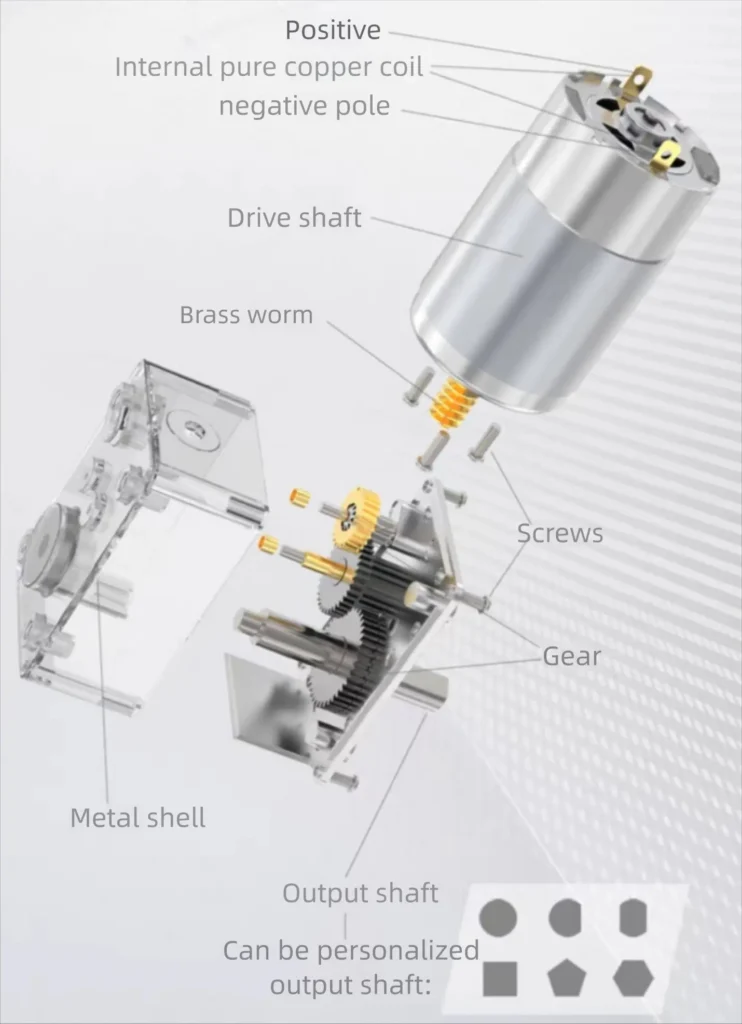
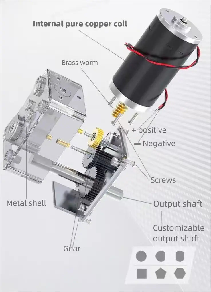
- The micro worm gearbox consists of a single-stage worm and a spur gear transmission system.
- Enveloping worm geometry can improve tooth contact, load distribution and efficiency, but increases manufacturing cost.
- In the worm gearbox, the brass worm wheel reduces friction and noise, while the steel spur gear ensures strength.
- The worm gearbox is suitable for micro actuators, robotic hands, medical devices, and smart hardware.
What is a Worm Gearbox?
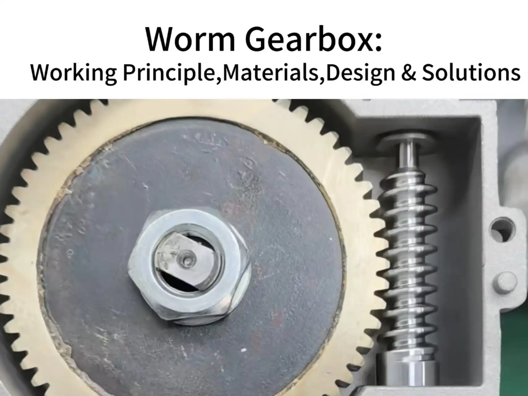
A worm gearbox is a transmission consisting primarily of a screw-like worm and a mating worm wheel. The worm is normally the input component, while the worm wheel drives the output shaft. Their axes are non-parallel and non-intersecting, and are most commonly arranged at 90 degrees.
- Worm: The screw-like driving component, manufactured with one or more starts.
- Worm wheel: The mating driven gear, with teeth designed to match the worm geometry.
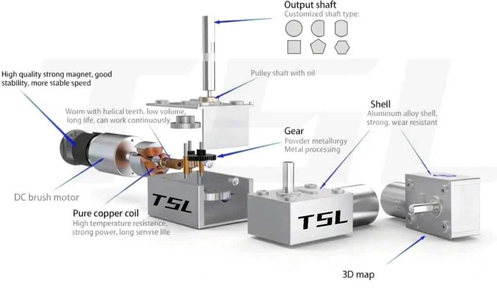
Unlike a standard spur gear pair, worm gearing involves both rolling and sliding contact, with sliding usually being the dominant motion. This allows a large reduction ratio and smooth transmission in a compact space, but it also makes friction, lubrication, material selection, surface finish and temperature rise important design considerations.
A complete worm gearbox also includes bearings, shafts, housing and lubrication. Even when two gearboxes use the same nominal reduction ratio, differences in tooth geometry, shaft support and manufacturing accuracy can result in different efficiency, backlash, noise, temperature rise and service life.
How Does a Worm Gearbox Work?
The working principle of a worm gearbox is essentially the transmission process of the worm and worm wheel.
The transmission process of a worm gear can be imagined as a screw (the worm) turning a specially designed nut (the worm wheel).
Input rotation: The motor or power source drives the worm along its axis.
Helical push: The worm’s helical teeth slide along the worm wheel teeth, generating two key forces:
- Tangential force: rotates the worm wheel.
- Normal force: keeps the teeth engaged and creates friction.
Reduced output: The worm rotates many times to turn the worm wheel once, producing a large reduction ratio and amplifying torque.
For a basic worm pair in which the worm is the input and the worm wheel is the output:
Gear ratio = Number of worm-wheel teeth ÷ Number of worm starts
For example, a 40-tooth worm wheel driven by a single-start worm has a theoretical ratio of 40:1. If the same wheel is driven by a two-start worm, the ratio becomes 20:1.
A multi-start worm generally has a larger lead angle. It can provide higher output speed and may improve transmission efficiency, but it also reduces the reduction ratio and usually weakens resistance to back-driving.
The approximate output values can be estimated as:
Output speed ≈ Input speed ÷ Gear ratio
Estimated output torque ≈ Input torque × Gear ratio × Gearbox efficiency
These equations are suitable for preliminary calculations, but the calculated torque must not be treated as the gearbox’s rated output torque.
For TSL Motor solutions, the rated output torque is provided for the complete motor-and-gearbox configuration. Customers can therefore evaluate the required operating point directly without separately calculating the gearbox’s allowable continuous torque. The published rated torque and its test conditions should take priority over the theoretical torque calculation.
Why Can Worm Gearbox Self-Lock?
When the worm has a shallow thread angle and high friction, you cannot turn the worm by twisting the nut. This is the principle of self-locking.
In a worm screw gearbox, the lead angle of the worm is usually very small. When the lead angle is smaller than the friction angle, the worm wheel teeth cannot overcome friction to drive the worm.
This is the core condition of self-locking.
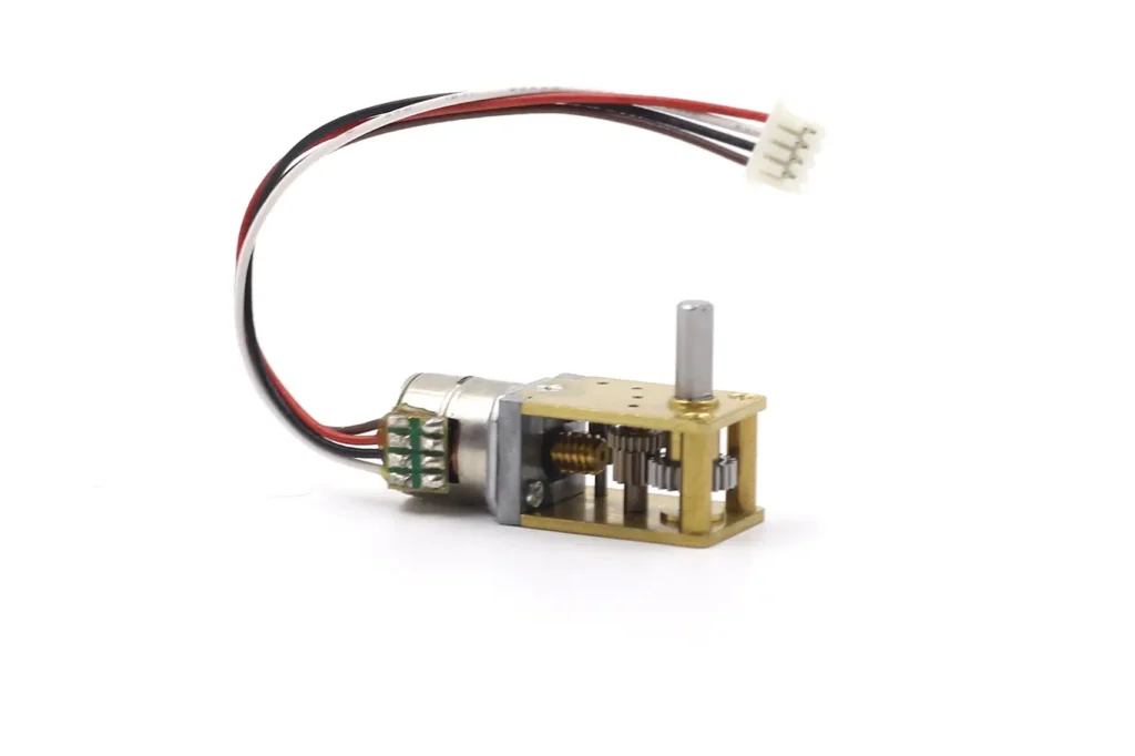
The worm can easily drive the worm wheel, because the power source provides enough tangential force. But the worm wheel cannot back-drive the worm, since its force is not enough to overcome friction and geometry.
Sliding friction not only reduces efficiency, but also creates damping when no power is applied. This further enhances the self-locking effect.
Safety Note: Resistance to back-driving must not automatically be treated as a holding brake. OSHA guidance also distinguishes a worm drive gearbox from an independent holding brake. Applications involving lifting, personal safety or valuable equipment should use a separate brake or mechanical locking device where required.
Advantages of Worm Gearboxes
The main value of a worm gearbox is not maximum transmission efficiency. Its advantages come from combining a large reduction ratio, a right-angle output and possible resistance to back-driving within a compact mechanical layout.
Single-stage high reduction:
A worm pair can achieve a relatively large reduction ratio in one stage, reducing the number of additional gear stages required. This can simplify the overall transmission structure, although the usable output torque must still remain within the gearbox’s rated limit.
Compact Right-Angle Layout
The input and output shafts are commonly arranged at 90 degrees. This allows the motor to be installed alongside the driven mechanism instead of extending directly behind the output shaft, which can reduce the required axial installation length.
Resistance to Back-Driving
A suitably designed worm gearbox can resist external torque applied from the output side. This can reduce unintended load movement after the drive stops, but the actual holding performance must be verified under the intended load, temperature, vibration and wear conditions.
Note: Self-locking is not absolute. In strong vibration or impact, backup brakes are recommended.
Smooth and quiet
The sliding-dominant tooth contact can reduce abrupt tooth engagement and support smooth operation. However, noise also depends on tooth accuracy, surface finish, lubrication, bearings, housing stiffness and assembly quality, so a worm gearbox should not automatically be described as quieter than every other gearbox type.
These advantages come with trade-offs. Sliding contact normally produces more power loss and heat than an efficient spur or planetary transmission, and a worm gearbox still has backlash. If high efficiency, frequent bidirectional operation or easy back-driving is more important than right-angle packaging, a Stirnradmotor may be a more suitable starting point.
Typical Applications of Worm Gearboxes
A worm gearbox is most useful when an application needs several characteristics at the same time: a right-angle output, a relatively large reduction ratio, low output speed and some resistance to back-driving. It should not be selected only because the application requires higher torque.
Micro Actuators & Positioning Systems
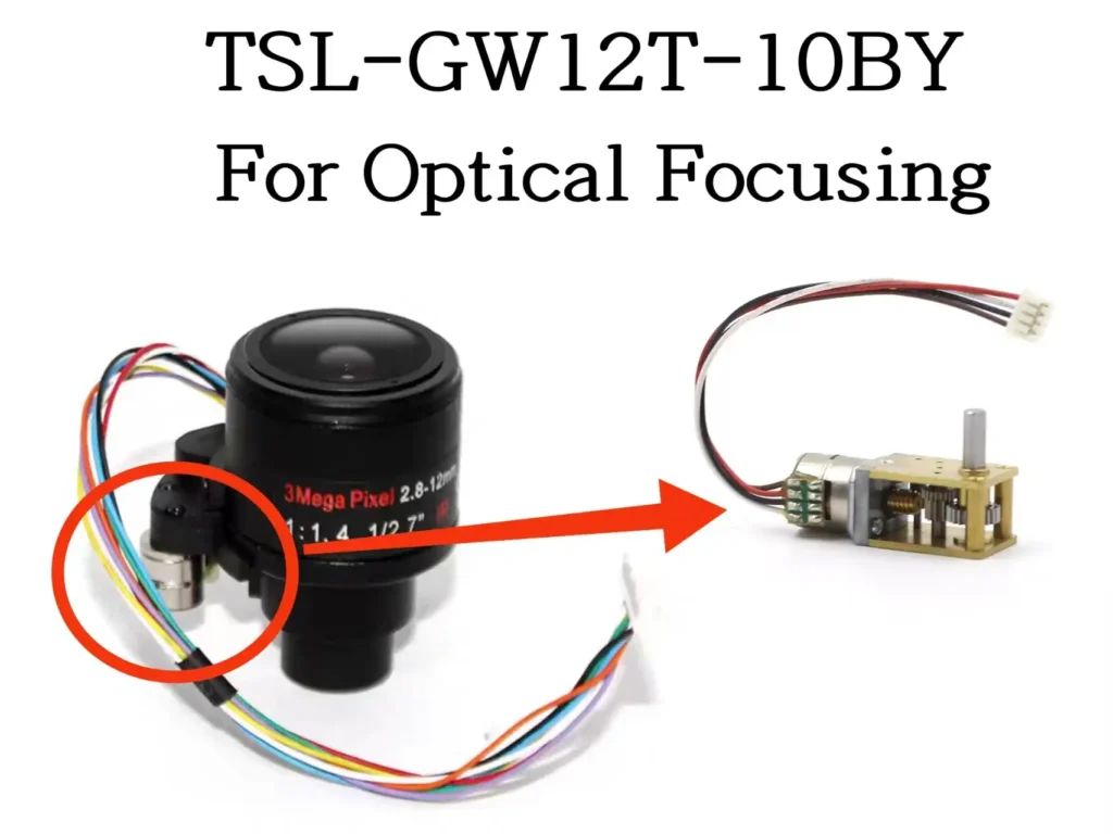
In focusing mechanisms, adjustment platforms and compact linear actuators, the worm gearbox can redirect motor rotation by 90 degrees before driving a lead screw, cam or linkage. Resistance to back-driving can help limit position movement after power is removed, although backlash must still be included in the positioning error budget.
Dexterous Hands and Thumb Mechanisms
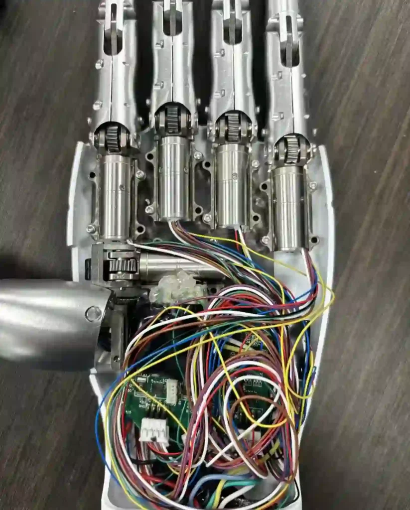
A right-angle transmission allows the motor body to be installed along the finger or inside the palm while the worm wheel drives a perpendicular joint, gear or linkage. This can simplify packaging in a thumb or finger actuator, but efficiency, backlash, temperature rise and joint holding tests must be evaluated together.
Medical and Laboratory Equipment
Worm gearboxes can be used in sample-handling mechanisms, compact adjustment modules, hospital-bed actuators and laboratory instruments that require slow, controlled motion. Smooth operation and resistance to back-driving may be beneficial, but safety-related positioning must not rely on gearbox friction alone.
Valves and Fluid Control Actuators
Valve mechanisms often require low speed and substantial starting torque to move the valve stem against seal friction or fluid pressure. A worm gearbox can provide a compact right-angle drive, but the rated output torque, starting load, duty cycle and temperature rise must be checked under the actual operating conditions.
Micro-Automation and Smart Hardware
Smart locks, electric shutters, dispensing mechanisms and compact automation modules may use worm gearboxes when installation space and output direction are restricted. For frequent cycling or battery-powered operation, efficiency and energy consumption should be verified instead of assuming that a large reduction ratio will automatically provide the best solution.
When Is a Worm Gearbox Not the Best Choice?
A worm gearbox may not be the preferred option when the application requires very high continuous efficiency, easy back-driving, extremely low backlash, high output speed or frequent continuous operation with limited cooling. In these cases, a spur, planetary or another gearbox structure may offer a better engineering balance.
Representative integrated products and available form factors can be found in the TSL Motor worm gear motor range. Final selection should still be based on the required output speed, rated torque, duty cycle, holding requirement and installation envelope.
Worm Gearbox:Why Worm Gear+ Spur Gears for Larger Reduction Ratios?
A large total reduction ratio can be achieved with multiple worm stages, but this is not always the most efficient solution. Each worm pair introduces sliding friction, power loss and heat, so the efficiency losses accumulate as additional stages are added.
Limitations of Worm and Gear
The overall efficiency of a multi-stage gearbox is calculated by multiplying the efficiency of each stage:
Overall efficiency = Stage 1 efficiency × Stage 2 efficiency × Additional stage efficiencies
For this reason, two worm stages can have a much lower total efficiency than either stage considered separately. The additional sliding contact can also increase starting resistance, lubricant requirements, temperature rise and wear.
Reasonable Division of Labor
- First stage: Worm and gear → Quickly obtain a large reduction ratio in limited space. Meanwhile, provide self-locking performance.
- Subsequent stages: Spur gears → Further amplify the reduction ratio. They feature high efficiency, strong transmission strength and long service life.
Worm Stage Followed by Spur Gear Stages
In many micro worm gearboxes, the motor first drives the worm. The worm and worm wheel provide the primary reduction and change the transmission direction. One or more spur gear stages are then used after the worm wheel to increase the total reduction ratio and transmit torque to the final output shaft.
Compared with adding another worm pair, spur gears use rolling-dominant tooth contact and normally introduce less friction and heat. They are also easier to manufacture and are well suited to multi-stage reduction. This arrangement allows the worm stage to provide the right-angle transmission and resistance to back-driving, while the spur stages provide additional reduction more efficiently.
When a planetary gearbox is combined with a worm drive, the planetary gearbox is positioned before the worm stage:
Motor → Planetary Gearbox → Worm Drive → Output
The planetary gearbox first reduces motor speed and increases the torque delivered to the worm stage. The final worm drive then changes the output direction and provides the required resistance to back-driving. A planetary gearbox is not added after the worm stage in this TSL Motor transmission architecture.
Enveloping Worm Drives: Higher Efficiency at Higher Cost
An enveloping worm drive uses tooth geometry that conforms more closely to the mating worm wheel. The larger contact area allows more tooth surface to share the load. With suitable geometry, materials, surface finish and lubrication, this structure can improve load distribution, load capacity and transmission efficiency.
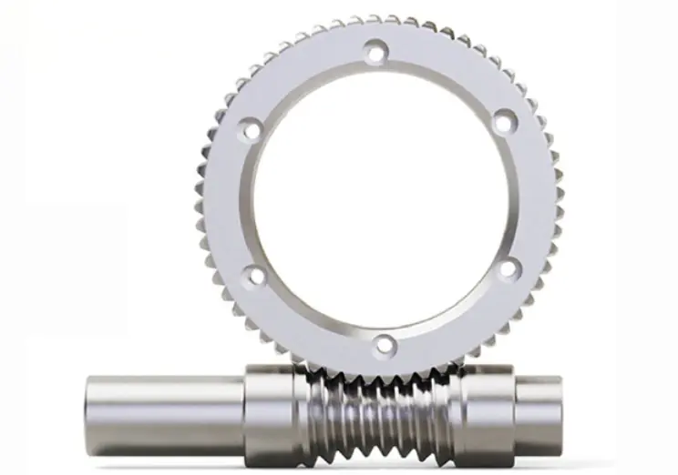
The performance improvement comes with higher manufacturing requirements. Enveloping tooth profiles require more precise machining, specialized tooling, stricter centre-distance control and more accurate assembly alignment. If the worm and worm wheel are not correctly aligned, the expected contact advantage may be reduced.
An enveloping worm structure therefore increases manufacturing and inspection costs. It is most appropriate when the application genuinely benefits from higher load capacity, improved efficiency or a smaller gearbox size, rather than being used as a standard solution for every worm gearbox.
How Does TSL Motor Select Worm and Worm-Wheel Materials?
There is no universally best material combination for a worm gearbox. TSL Motor selects the worm and worm-wheel materials according to the required torque, gearbox size, noise, duty cycle, operating temperature, expected life and production cost of the actual application.
| Anwendung | Worm Material | Worm-Wheel Material | Main Design Priority |
|---|---|---|---|
| Dexterous hand actuators | Stahl | Stahl | High strength and load capacity within a very small gearbox |
| Automation equipment | Stahl | POM | Low noise, smooth operation and controlled manufacturing cost |
| Consumer products | Brass | Powder metallurgy | Cost-effective mass production and consistent part geometry |
| Inspection and testing equipment | Stahl | Brass | Smooth motion, controlled wear and stable positioning |
TSL Motor evaluates the complete gear pair through rated-load, temperature-rise, noise and durability testing before confirming a material combination. Customers can submit their operating conditions through our custom geared motor solutions for application-specific evaluation.
TSL MOTOR Micro DC Motor with Worm Gearbox
TSL Motor does not normally supply the worm gearbox as a standalone component. We develop integrated assemblies in which the motor, reduction stages, bearings, housing, lubricant and output shaft are matched as one system.
Depending on the application, the worm gearbox can be combined with a brushed DC motor, brushless DC motor or stepper motor. Integrated design makes it easier to control loaded output speed, rated torque, current, temperature rise, noise and service life than selecting the motor and gearbox independently.
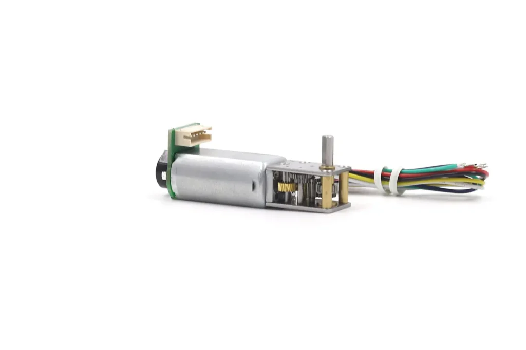
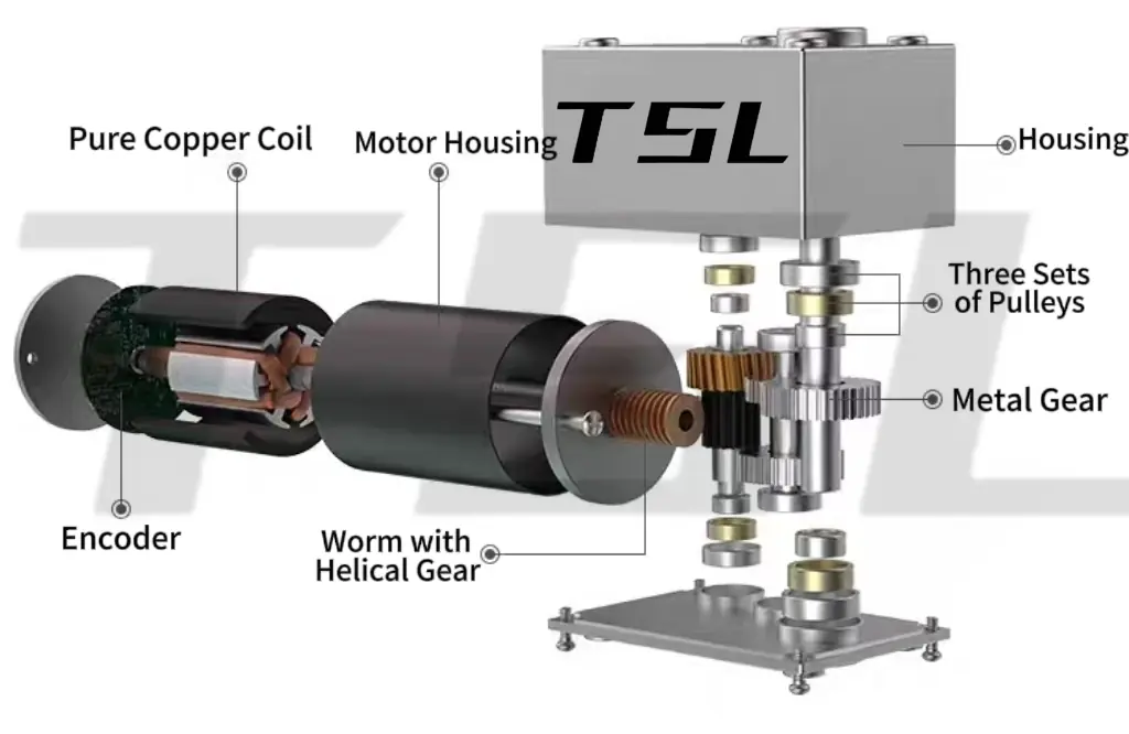
Architecture 1: Motor, Worm Stage and Spur Gear Stages
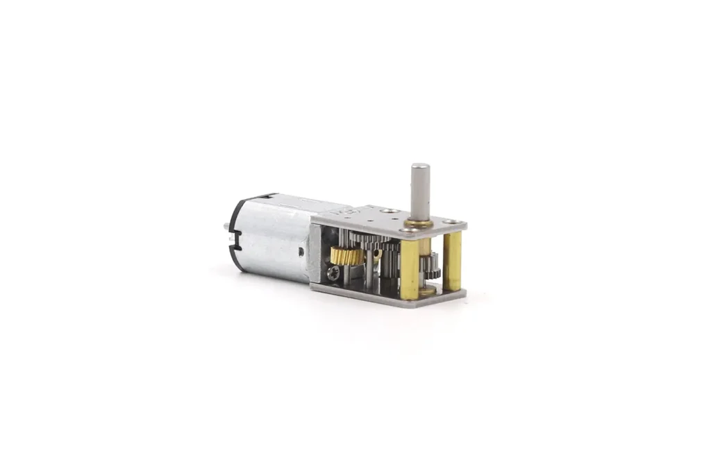
In a standard micro worm gear motor, the motor first drives the worm. The worm and worm wheel provide the initial reduction and change the transmission direction. One or more spur gear stages are then added after the worm wheel to obtain the required total ratio and final output-shaft position.
Architecture 2: Motor, Planetary Gearbox and Final Worm Stage
When a higher reduction ratio or greater torque density is required within a limited installation space, a planetary gearbox can be positioned before the worm stage:
Motor → Planetary Gearbox → Worm Drive → Output
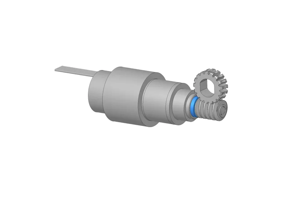
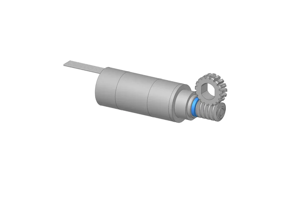
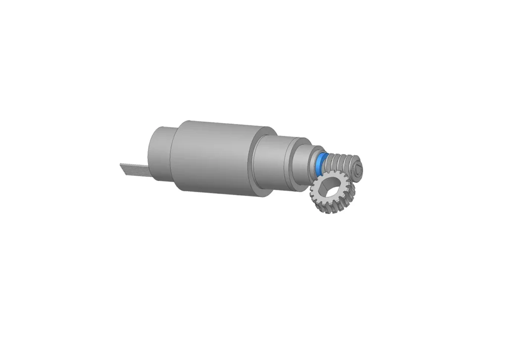
The planetary gearbox first reduces motor speed and increases the torque delivered to the worm. The final worm stage then changes the transmission direction and provides the required resistance to back-driving. Because the worm stage receives a higher input torque in this arrangement, its tooth load, bearing support, lubrication and temperature rise must be checked carefully.
Rated Output Torque Provided for the Complete Assembly
To simplify customer selection, TSL Motor provides the rated output torque for the complete motor-and-gearbox assembly. Customers can compare this value directly with the required continuous operating torque without separately calculating the gearbox’s allowable continuous torque.
The rated output torque considers the motor’s thermal capability together with the gearbox’s mechanical and thermal limits. If a project requires a separate mechanical review, TSL Motor can also provide the allowable continuous gearbox torque and the corresponding test conditions.
Information Required for Customization
For an application-specific worm gear motor, the following information should be confirmed:
- Required loaded output speed;
- Rated operating torque;
- Peak torque and peak duration;
- Supply voltage and current limit;
- Duty cycle and continuous running time;
- Back-driving or holding requirement;
- Installation envelope and mounting points;
- Output-shaft direction, diameter, length and shape;
- Operating temperature, noise and lifetime targets;
- Wire length, connector and feedback requirements.
Output Interface and Validation
TSL Motor can customize the output-shaft diameter, length and direction, as well as D-cut shafts, flat shafts, threaded shafts, splines, hollow shafts and application-specific interfaces. Housing shape, mounting holes, wires and connectors can also be adjusted where the gearbox design permits.
The final configuration should be verified under representative load, duty cycle and environmental conditions. Rated-load performance, temperature rise, noise, resistance to back-driving and durability should be evaluated as a complete assembly rather than as independent motor and gearbox specifications.
Structural Design Logic
All TSL MOTOR worm gear geared motors adopt single-stage worm gear output.This is because multi-stage worm gear series connection tends to cause efficiency loss and excessive heat generation.We ensure system service life and stability from the structural design stage.
Two Proven Solution Architectures
With over 15 years of manufacturing and R&D experience, TSL MOTOR has not only accumulated abundant engineering application data.We have also developed two mature, validated worm gear geared motor solutions:
Spur/Planetary Gearbox + Worm Gear Combination
The front or middle stage uses spur or planetary gear mechanisms for high-efficiency speed reduction.The motor output shaft directly drives the worm gear, which serves as the critical stage to achieve large reduction ratio and self-locking function.
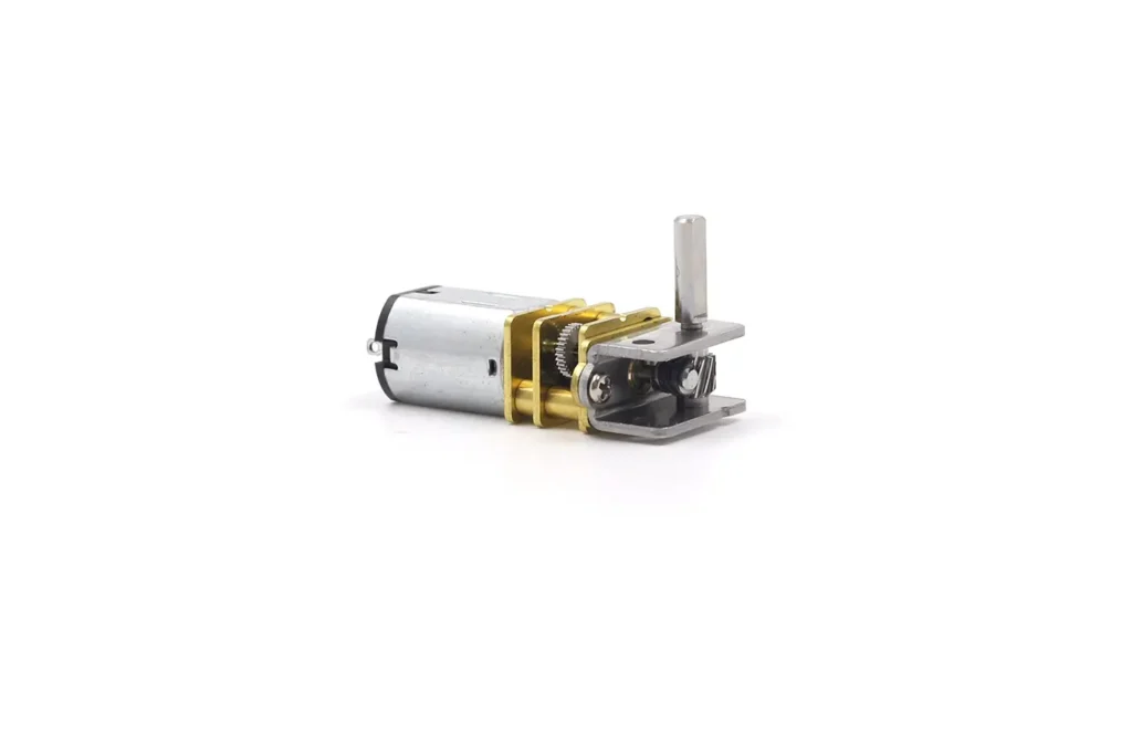
This design balances motor efficiency, torque density and compactness.It is suitable for micro systems with high performance requirements.
Standardized Worm Gear Geared Motor
The motor output shaft is connected to a single-stage worm gear transmission.Subsequent transmission is completed by spur gears.This solution features a simple structure and compact size.
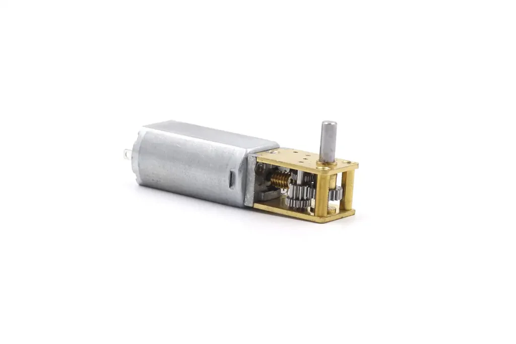
It meets the requirements of self-locking, low-speed high-torque output and space constraints.It is ideal for mass production and mature application scenarios.
Customization & Engineering Optimization
TSL MOTOR is always customer-oriented.We do not simply “stack parameters”.Instead, we carry out engineering optimization based on years of experience.We comprehensively consider load characteristics, operating conditions and space limitations.Products are delivered only after full internal testing and evaluation, ensuring reliability and consistency.
Output Shaft Customization
We support customization of shaft diameter, shaft length, D-shaped shaft, flat shaft, spline shaft, hollow shaft and special interface structures.This facilitates direct integration with customer systems.
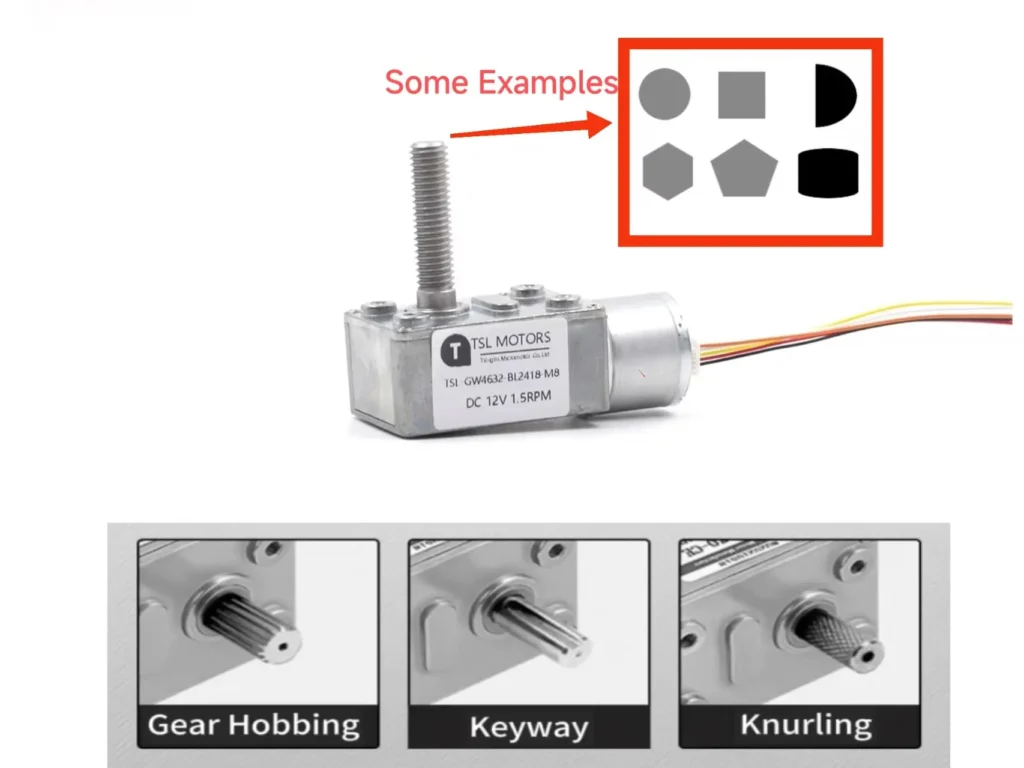
Through integrated design, rational structural division of labor and engineering customization, TSL MOTOR’s micro worm gear geared motors not only ensure performance and reliability.They also provide flexible integration methods, suitable for various precision and intelligent application scenarios.
Fazit
A worm gearbox is most valuable when an application needs a large reduction ratio, a compact right-angle transmission and resistance to back-driving. It is not normally selected for maximum efficiency, and its actual performance cannot be judged from the reduction ratio alone. Worm geometry, materials, lubrication, manufacturing accuracy, load and operating temperature must be evaluated together.
There is also no single structure or material combination suitable for every application. Multiple worm stages are possible but accumulate efficiency losses; spur gears are often used after the worm stage for additional reduction, while a planetary gearbox must be positioned before the worm stage in TSL Motor’s combined architecture. Enveloping worm geometry can improve contact, load capacity and efficiency, but it also increases machining and assembly cost.
TSL Motor provides the rated output torque for the complete motor-and-gearbox assembly, allowing customers to evaluate the operating point directly. Before confirming a solution, the required loaded speed, rated and peak torque, duty cycle, holding requirement, installation space, output interface, operating temperature and expected service life should be clearly defined.
FAQ
Q1:Are All Worm Gearboxes Self-Locking?
No. Self-locking depends mainly on the worm lead angle, number of starts, friction, materials, lubrication and operating conditions. A high reduction ratio may increase resistance to back-driving, but it does not guarantee that the gearbox will hold the load.
Q2:Does Self-Locking Mean That the Gearbox Has No Backlash?
No. Self-locking and backlash are different characteristics. Self-locking concerns whether the output can drive the worm backward, while backlash is the angular clearance that appears when the direction of rotation or load changes.
Q3:Can a Worm Gearbox Use More Than One Worm Stage?
Yes. Multiple worm stages can provide an extremely large reduction ratio or change the transmission direction more than once. However, the efficiency losses and heat generation of each worm stage accumulate. For this reason, additional reduction is often achieved with spur gears after the worm stage.
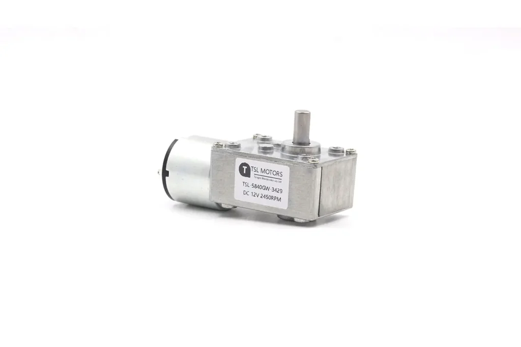
Schneckengetriebemotor
TSL Motors is a leading manufacturer specializing in custom worm gear motors, offering dependable solutions tailored to meet the specific needs of various applications. With our in-depth knowledge of DC worm gear motors and gear technology, we assist OEMs in developing, identifying, and implementing innovative geared motor solutions with greater speed. These compact, quiet, self-locking motors, also capable of static damping, provide exceptional torque density.