
When designing compact automation equipment, medical instruments, robot joints, or smart logistics modules, the choice of the drive unit often determines the overall performance ceiling of the machine.
With their small size, convenient control, and high output torque, DC gear motors have become the core components in small-to-medium motion control scenarios.
However, facing a series of parameter datasheets, the first hurdle for many engineers is not the control algorithm, but a set of seemingly basic calculations: How much torque does my load actually need? How high a speed is required? Can a standard gear motor satisfy these needs? If parameters sit right at the critical threshold, should custom micro motors be considered?
Key Takeaways
- Start from the Load: Size your motor by first identifying the required output speed and torque.
- Master the Core Formula: Use Torque = Force × Radius to calculate baseline static loads.
- Include Safety Margins: Add a safety margin to account for friction, wear, and mechanical shock.
- Account for Acceleration: Calculate inertial torque for fast starts and frequent reversals.
- Factor in Gear Efficiency: Deduct gearbox mechanical efficiency losses when solving for motor torque.
- Know Your Torque Limits: Size based on continuous operating torque—never stall torque.
- Evaluate Customization: Consider custom micro motors when standard units fall short on specs or size.
The Relationship Between Torque, Speed, and Power
The three most common parameters in motor selection are torque, speed, and power—and they are not independent of each other.
Torque can be understood as the capacity of a shaft to generate rotational action. The most fundamental formula is:
T = F × r
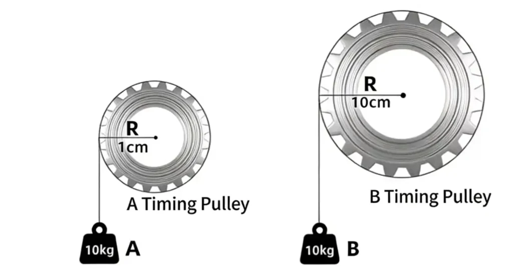
Where:
- T: Torque, in N·m
- F: Force acting in the tangential direction, in N
- r: Distance from the point of force application to the center of rotation, in m
When reviewing different motor or gearbox specifications, torque units are not always consistent. Some products use N·m or mN·m, while others use kg·cm, N·cm, or lb·in. To avoid motor selection errors caused by unit conversion, you can use TSL MOTOR’s Torque Unit Converter to quickly convert between commonly used torque units.
For example, if a drum with a radius of 20 mm needs to generate a pulling force of 20 N, the theoretical load torque is:
T = 20 N × 0.02 m = 0.4 N·m
Though simple, this formula is extremely important. Lifting mechanisms, pulleys, robotic arms, wire‑spooling mechanisms, valves, and a vast array of miniature actuators can ultimately be converted into a “force × lever arm” format for initial calculation.
Start by calculating the load torque from the load force and application radius, then proceed to calculate acceleration torque and total required motor torque.Speed and power can be converted using:
P = T × ω
Where angular velocity is:
ω = 2π n / 60
Using standard engineering units (kW for power and rpm for rotational speed), it can also be expressed as:
T = 9550 × P / n
Note that while this formula is useful for checking how much mechanical power is required at a specific operating point, motor selection cannot be completed solely based on power. Two motors with identical power ratings may have completely different speeds, torques, and thermal characteristics.
Motor Sizing Should Start From the “Load Side”
When performing actual motor sizing, it is recommended to first answer two questions:
- How fast does the output end need to run?
- How much torque does the output end require?
For example, if the equipment requires a final output speed of 100 rpm, 100 rpm should be set as the target first, rather than picking a 6000 rpm motor and figure out how to use it later.
Similarly, if the load requires 0.5 N·m, set 0.5 N·m as the load‑side requirement first, and then calculate backwards through the gearbox to determine the torque the motor needs to supply.
This “backwards calculation from load to motor” approach avoids a very common mistake: the motor itself appears to have sufficient power, but once combined with a gearbox, the actual output speed, continuous torque, or gearbox load capacity fails to match requirements.
How to Calculate Common Load Torques
Although load torque calculation methods vary slightly across different mechanical structures, the underlying logic remains similar.
Spool or Hoist Mechanisms
Suppose a 3 kg object needs to be vertically lifted using a drum with a radius of 15 mm.
The gravitational force generated by the object is approximately:
F = m × g = 3 kg × 9.81 m/s² = 29.43 N
The load torque is:
T = 29.43 N × 0.015 m ≈ 0.441 N·m
This means that, ignoring friction and other losses, the output shaft must supply at least 0.441 N·m.
In real‑world selection, however, you cannot select exactly 0.441 N·m because starting shock, mechanical friction, assembly tolerances, and long‑term wear all impact the actual load. A safety margin must be added.
While a typical safety margin of about 50% serves as a preliminary baseline for many applications, the actual safety factor should be determined according to specific load fluctuations and equipment demands.
If a preliminary safety factor of 1.5 is applied to this example:
Tdesign = 0.441 × 1.5 ≈ 0.662 N·m
This updated figure is the proper target value to take into the next gear motor calculation step.
Horizontal Conveyor Mechanisms
For simple horizontal conveyance systems, estimate movement resistance first:
F = μ × m × g
Then calculate based on drive‑wheel radius:
T = F × r
However, real conveyor belt systems usually involve belt pre‑tensioning, bearing resistance, roller resistance, and starting inertia. Therefore, calculated results serve better as preliminary selection guidelines rather than final test values.
If the equipment is already built, directly measuring the actual starting pull force or shaft torque is often more reliable than theoretical calculations alone.
Don’t Ignore Torque Required for Starting and Acceleration
Many sizing errors occur during starting rather than steady-state operation.
When running at a steady speed, the motor mainly overcomes load and friction; however, when accelerating from rest to the target speed, it must also overcome the system’s moment of inertia.
Acceleration torque can be expressed as:
Tacc = J × α
Where: J: Reflected moment of inertia
α: Angular acceleration
If equipment requires rapid acceleration from 0 to full speed, acceleration torque may even significantly exceed steady‑state load torque.
Total required torque should be viewed as a combination of load torque and acceleration torque, multiplied by a safety factor:
Required Torque ≈ (Tload + Tacc) × Safety Factor
If starting acceleration is very slow, acceleration torque has a smaller impact; however, for robot joints, grippers, automatic doors, rapid positioning systems, or mechanisms with frequent start/stop and reversal cycles, acceleration torque must be thoroughly accounted for.
How to Calculate Gear Ratio
Once the target output speed is established, you can begin gear motor calculation using the basic relation:
i = n_motor / n_out
- Where: i: Gear ratio
- n_motor: Motor speed
- n_out: Gearbox output speed
For example, if the desired output speed is 100 rpm and the motor operates comfortably around 5000 rpm, the theoretical gear ratio is:
i = 5000 / 100 = 50
This indicates a gear ratio of approximately 50:1. However, exact 50:1 ratios may not exist in commercial off-the-shelf products; available options might be standard ratios like 46:1, 51:1, or 60:1.
In this case, compare the final output speed, output torque, and actual motor operating point together, rather than mechanically selecting the closest mathematical integer.
Determine achievable ratios based on output operating speed and maximum allowable input speed of the gearbox, then select the most suitable combination from standard options.
Torque After Reduction Is Not Simply Multiplied by Gear Ratio
In an ideal state, a 50:1 gearbox seems to multiply motor torque by 50×, but actual gear transmissions always incur losses. Therefore:
T_out = T_motor × i × η
Conversely:
T_motor = T_out / (i × η)
Where η is gearbox efficiency.
Assuming the previously mentioned hoisting mechanism requires:
- Output torque: 0.662 N·m
- Gear ratio: 100:1
- Estimated combined efficiency: 70%
The required motor torque is:
T_motor = 0.662 / (100 × 0.70) ≈ 0.00946 N·m = 9.46 mN·m
If the output speed requirement is 60 rpm, then with a 100:1 reduction, the corresponding motor operating speed is:
60 × 100 = 6000 rpm
What needs to be found is not a “0.662 N·m motor,” but rather a motor capable of continuously outputting approximately 9.46 mN·m at around 6000 rpm while mated to a 100:1 gearbox. This step is the most crucial milestone in gear motor selection.
Don’t Confuse Continuous, Peak, and Stall Torque
When reviewing micro DC motor datasheets, you will frequently encounter:
- Rated Torque / Nominal Torque
- Maximum Continuous Torque
- Peak Torque
- Stall Torque
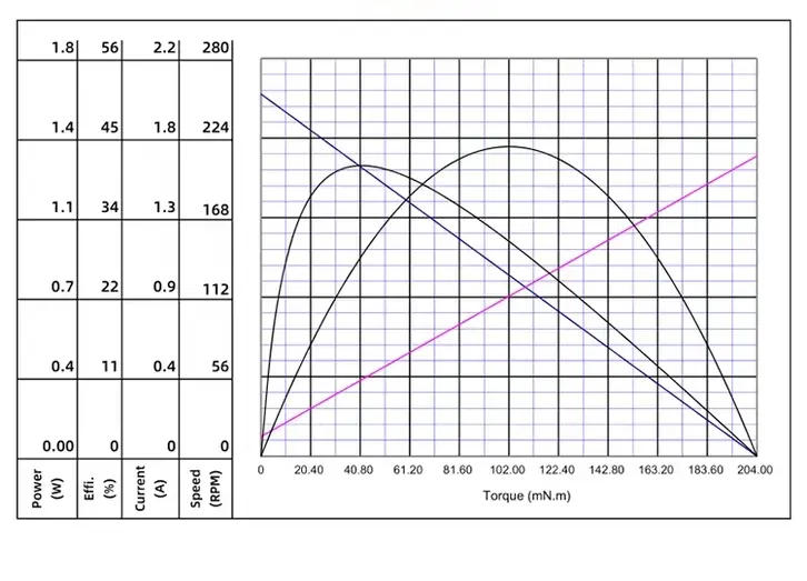
The most commonly misused value is Stall Torque.
Stall torque represents the torque generated when the motor shaft is completely prevented from rotating 0 rpm speed, usually accompanied by high current draws). It does not represent a normal continuous operating point.
When selecting motors for continuous-duty equipment, check continuous torque first. For short-duration starting, clamping, or rapid acceleration, evaluate peak torque and its allowable duration. Consider speed-torque characteristics and continuous working capacity separately, keeping in mind that motor parameters are affected by temperature.
Furthermore, even if the motor body can deliver high instantaneous torque, it must not exceed the gearbox’s maximum allowable output torque; otherwise, gears, shafts, or bearings may fail before the motor itself sustains damage.
Initial Selection Steps for Gear Motors
If equipment load and speed requirements are known, proceed with the following sequence:
Determine Target Output Speed: Confirm the required rpm for the final output shaft, roller, or mechanism, or convert linear velocity to rotational speed.
Calculate Load Torque: Convert actual physical loads into N·m or mN·m based on mass, friction, pulling force, drum radius, or mechanism dimensions.
Account for Starting and Acceleration: Add acceleration torque for applications involving frequent start/stops, fast acceleration, or high system inertia.
Apply a Reasonable Safety Margin: Factor in friction variation, manufacturing tolerances, aging, and load fluctuations rather than operating the motor near its absolute limit.
Calculate Gear Ratio from Motor Speed: Determine preliminary gear ratio using i = n_motor / n_out, then pick a matching standard ratio from available products.
Calculate Motor Torque Considering Gearbox Efficiency: Derive actual required motor torque using T_motor = T_out / (i × η).
Inspect Real Motor Performance Curves: Verify continuous torque, current, temperature rise, peak capacity at target speed, and gearbox strength limits—avoid relying solely on no-load speed and stall torque values.
Following these steps typically narrows dozens of candidates down to a few suitable specifications.
What Other Parameters Should Be Considered for Micro Gear Motors?
For micro drive systems, calculating torque and speed does not mark the end of the selection process.
Space inside micro equipment is often tight; confirm motor diameter, total length, gearbox form factor, and output shaft dimensions. For the electrical power system, verify whether nominal voltage, operating current, and starting peak current can be handled by the power supply and driver board.
If position or speed feedback is required, evaluate encoders, Hall sensors, or other feedback hardware. If used in robotics, medical devices, automation mechanisms, or battery-powered gear, factors like operational lifespan, noise levels, efficiency, backlash, weight, and temperature rise can determine final solution viability.
Modern motor selection tools use operating speed, torque, voltage, current, physical dimensions, and gearbox needs as simultaneous filtering criteria rather than relying on a single power parameter.
The ultimate goal of motor calculation is not to output a single mandatory model number, but to define a reasonable performance window.
Summary
The core workflow for motor torque and speed calculations can be summarized as:
Load → Output Torque → Output Speed → Acceleration Demand → Safety Margin → Gear Ratio → Efficiency Loss → Motor Operating Point
- Standard Solutions: If standard voltage, physical size, and off-the-shelf gear ratios cover the calculated operating point, compare matching DC gear motors, focusing on output speed, continuous torque, ratio options, and maximum load capacity.
- Custom Micro Motors: If standard off-the-shelf products cannot simultaneously meet constraints regarding size, voltage, shaft design, reduction ratio, encoder integration, noise limits, operational lifespan, or custom mounting geometry, consider custom micro motors.
By custom-matching motor windings, gearboxes, output shafts, and feedback hardware, the complete drive system can operate precisely at the equipment’s true optimal operating point, eliminating the need to simply settle for an oversized motor.