Published: NOVEMBER 23, 2025
Updated:SEPTEMBER 3, 2026
A spur gear motor combines an electric motor with a gearbox that uses straight-cut gears on parallel shafts. The gearbox reduces the motor’s speed and increases the available output torque, making the assembly suitable for mechanisms that cannot use the motor’s high-speed output directly.
Its simple gear geometry can support economical manufacturing and efficient power transmission, but actual performance depends on more than the gearbox type. Gear ratio, number of stages, tooth geometry, material, shaft support, lubrication and operating load all affect efficiency, backlash, noise, temperature and service life.
This article explains how a spur gear motor works, where its structural advantages come from and which design limits should be checked before it is applied. For available sizes, voltages and gearbox configurations, see our spur gear motor product range.
As one of China’s leading DC geared motor manufacturers, we understand the challenges engineers face when choosing the right power solution.
Whether you need standard specifications or tailor‑made designs, we provide a complete one‑stop service — from design and manufacturing to after‑sales support. This guide will walk you through the unique value of spur gear motors, helping you make the smartest choice for your next project.
Key Takeaways
- A spur gear motor combines an electric motor with one or more straight-tooth gear stages to reduce output speed and increase available output torque.
- Gear ratio determines the theoretical speed reduction, but actual output torque must account for gearbox efficiency and the gearbox’s continuous and peak torque limits.
- Spur gears are relatively simple to manufacture and do not generate the axial thrust associated with helical gears, but their shafts and bearings must still support radial gear forces.
- Efficiency, noise and temperature cannot be represented by one universal value. They change with the number of stages, transmitted load, gear material, tooth accuracy, lubrication, alignment and operating speed.
- Plastic gears can reduce weight and meshing noise, while metal gears can provide greater strength and temperature resistance. Neither material is automatically better for every application.
- Selection should begin with loaded output speed, continuous torque, peak torque, duty cycle and installation constraints—not with no-load speed or stall torque alone.
What Is a Spur Gear Motor?
Definition
A spur gear motor is an integrated assembly consisting of an electric motor and a gearbox that uses straight-tooth gears mounted on parallel shafts. The small pinion attached to the motor shaft drives one or more larger gears, reducing rotational speed before power reaches the output shaft.
A typical spur gearbox includes a motor pinion, intermediate compound gears, shafts or pins, bearings or bushings, an output gear and a housing. Unlike a planetary gearbox, its output shaft is often offset from the motor axis, although the final position depends on the specific gear-train layout.
The gearbox changes the relationship between speed and torque; it does not create additional mechanical power. Some input power is lost through tooth sliding, bearing friction, lubricant churning, seal drag and gear misalignment.
How Does a Spur Gear Motor Work?
For one external gear pair, the theoretical reduction ratio is:
Gear ratio = Number of teeth on the driven gear ÷ Number of teeth on the driving gear
i = Z₂ ÷ Z₁
If a 10-tooth pinion drives a 40-tooth gear, the stage ratio is 4:1. The driven gear rotates at approximately one-quarter of the pinion speed.
For a gearbox containing several reduction stages:
Total ratio = Stage 1 ratio × Stage 2 ratio × … × Final-stage ratio
The approximate output speed is:
Output speed ≈ Motor speed ÷ Total gear ratio
Output torque can be estimated as:
Estimated output torque ≈ Motor torque × Total gear ratio × Gearbox efficiency
The motor torque used in this calculation must correspond to the intended operating speed and load. Stall torque must not be substituted as a continuous operating value. The calculated output must also remain below the gearbox’s permissible continuous and peak torque ratings.
Actual gearbox efficiency varies with load, gear geometry, pitch-line speed, number of stages, bearing losses and lubrication. NASA research on spur-gear efficiency similarly shows that efficiency changes with gear size, pitch, ratio, speed and load.
For a complete calculation workflow, including load torque, output speed and efficiency correction, see How to Calculate Motor Torque and Speed for a DC Gear Motor Application.ces, toys, smart locks, pumps, and light robots. They are the most economical reduction solution.
Types Of Spur Gear Motor
Spur gear motors can be categorized in several ways depending on their construction, torque requirements, and application environment. Below are the main types most commonly used in industrial, commercial, and consumer products.
By Gear Material
The choice of material is the most important determinant of the motor’s load capacity, noise characteristics, lifespan, and environmental suitability. They can be classified into plastic spur gear motors and metal spur gear motors.
1.Plastic Spur Gear Motors
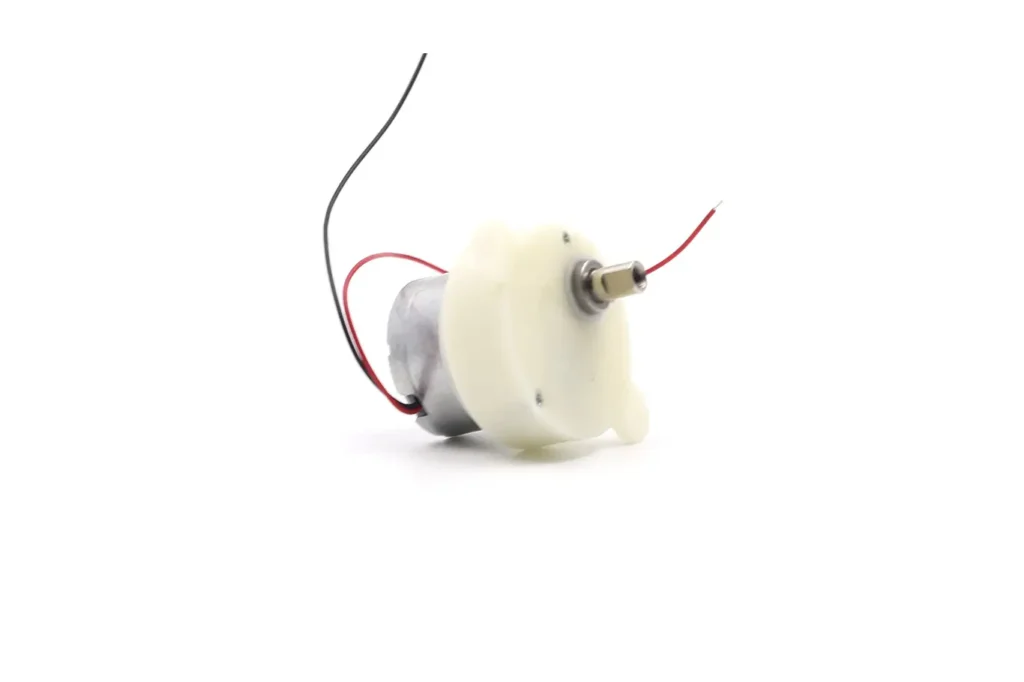
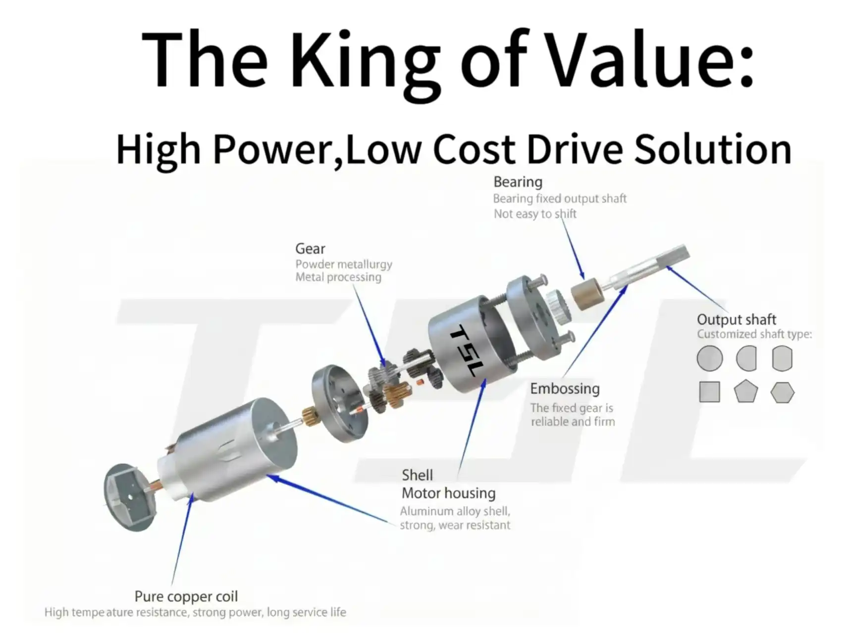
Plastic gears revolutionized the miniature motor industry, enabling the miniaturization of devices in consumer electronics and medical technology.
Advantages:
- Lightweight: Ideal for portable devices, reducing overall weight.
- Low Noise: Plastic gears absorb some vibration during meshing, reducing operational sound.
- Cost-Effective: Efficient for mass production through injection molding.
Limitations:
- Limited load capacity; prone to deformation under high load or high temperature.
- Shorter lifespan; not suitable for continuous heavy-duty work.
Typical Applications:
- Toy motors (electric cars, robots)
- Small appliances (electric toothbrushes, blenders, coffee makers)
- Consumer electronics (printers, optical drives, internal camera drives)
Advantages:
- High Strength: Can withstand greater torque and shock loads.
- Wear Resistance: Suitable for long-term continuous operation, reducing maintenance frequency.
- Long Lifespan: Can operate stably for many years in industrial environments.
Limitations:
- Higher cost; complex manufacturing process.
- Noisier than plastic gears; requires lubrication and precision machining to mitigate.
Typical Applications:
- Industrial automation (conveyors, robotic arms, packaging equipment)
- Precision instruments (medical equipment, measuring instruments)
- High-torque applications (power tools, locks, electric pumps)
2.Metal Spur Gear Motors (Brass / Steel)
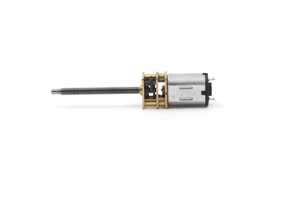
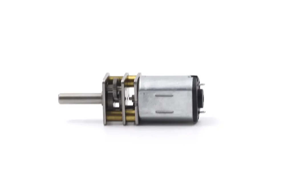
Metal gears are the industry standard for applications requiring high torque, impact resistance, and long service life. Brass gears offer good corrosion resistance, while steel gears provide superior strength and wear resistance.
By Motor Type
1.DC Brushed Spur Gear Motors
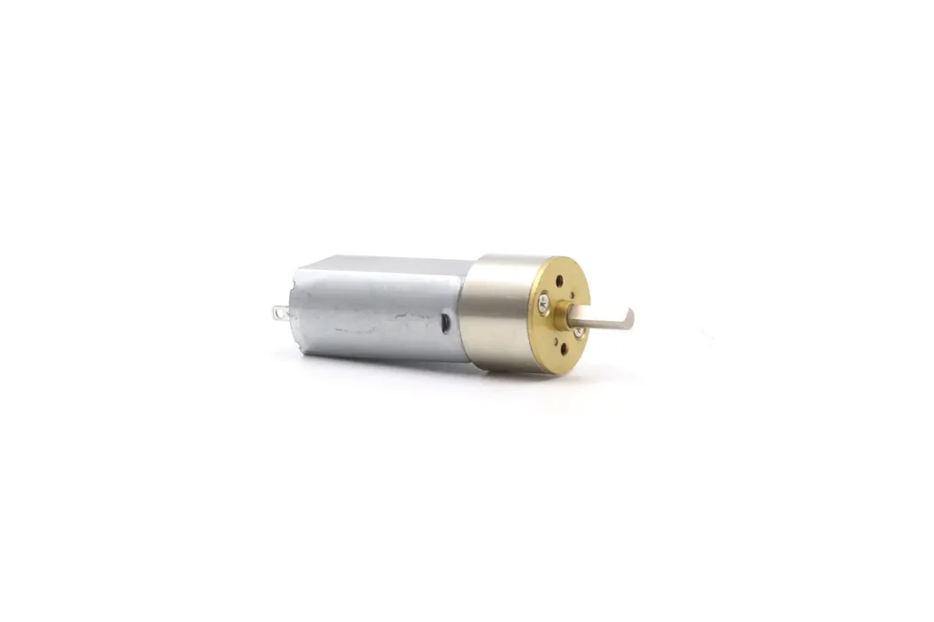
Working Principle::Current switching is achieved through carbon brushes and a commutator, driving the motor’s rotation.
- Pros:
- Low cost, simple control.
- Mature technology, easy to maintain.
- Cons:
- Limited lifespan due to carbon brush wear.
- Higher electrical noise.
- Typical Applications:
- Vending machines, actuators
- Home appliances (fans, blenders)
- Office equipment (printers, copiers)
Pros:
- High efficiency, low energy consumption.
- Long lifespan, minimal maintenance.
- Low electrical noise, suitable for precision equipment.
Cons:
- Higher cost.
- Complex control system.
Typical Applications:
- Medical devices (infusion pumps, surgical instruments)
- Smart locks, security systems
- Robotics and industrial automation
2.DC Brushless (BLDC) Spur Gear Motors
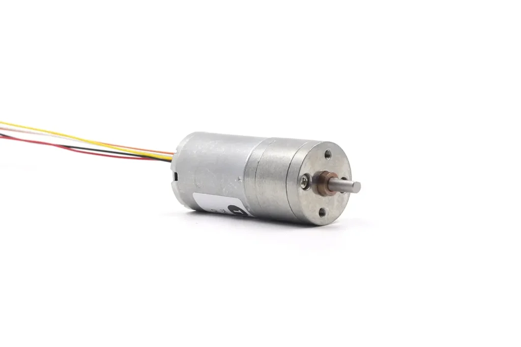
Working Principle: Current is controlled by an electronic commutator, eliminating the need for carbon brushes.
3.Stepper Spur Gear Motors

Working Principle: Driven by step pulses, the motor achieves precise angle control after gear reduction.
- Pros:
- High precision, capable of open-loop positioning.
- Simple control, suitable for low-speed, high-precision applications.
- Cons:
- Limited torque, lower efficiency.
- Prone to losing steps at high speeds.
- Typical Applications:
- Printers, scanners
- Camera lens focusing
- Small positioning systems, metering equipment
Pros:
- High efficiency, suitable for battery-powered devices.
- Fast response, suitable for dynamic control.
- Low noise, low vibration, smooth operation.
Cons:
- High cost.
- Limited load capacity, not suitable for heavy loads.
Typical Applications:
- High-end medical devices (micropumps, surgical robots)
- Precision instruments (optical equipment, laboratory automation)
- Consumer electronics (high-end cameras, smart wearables)
- Aeromodeling and drones
4.Coreless Spur Gear Motors
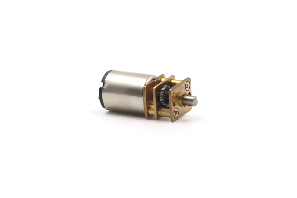
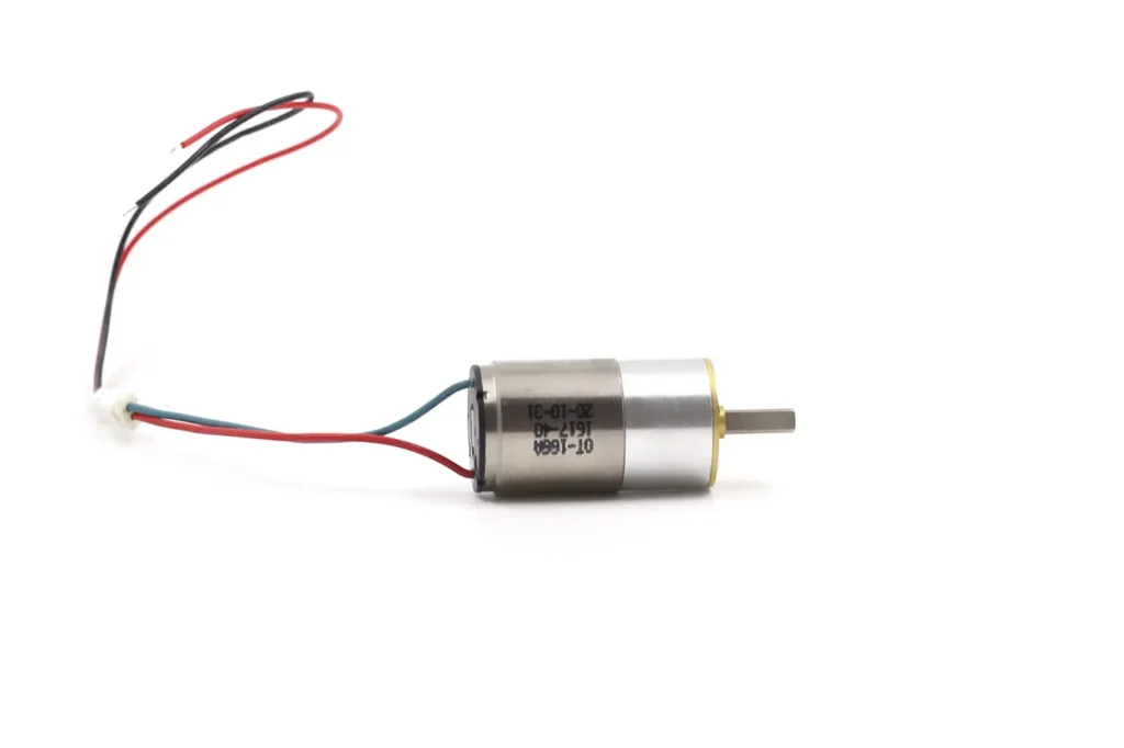
Working Principle: Uses a coreless rotor motor (hollow cup), resulting in extremely low inertia and fast response speed.
By Output Configuration
The internal arrangement of the gears determines the relationship between the motor axis and the output axis.
1.Inline Spur Gear Motor
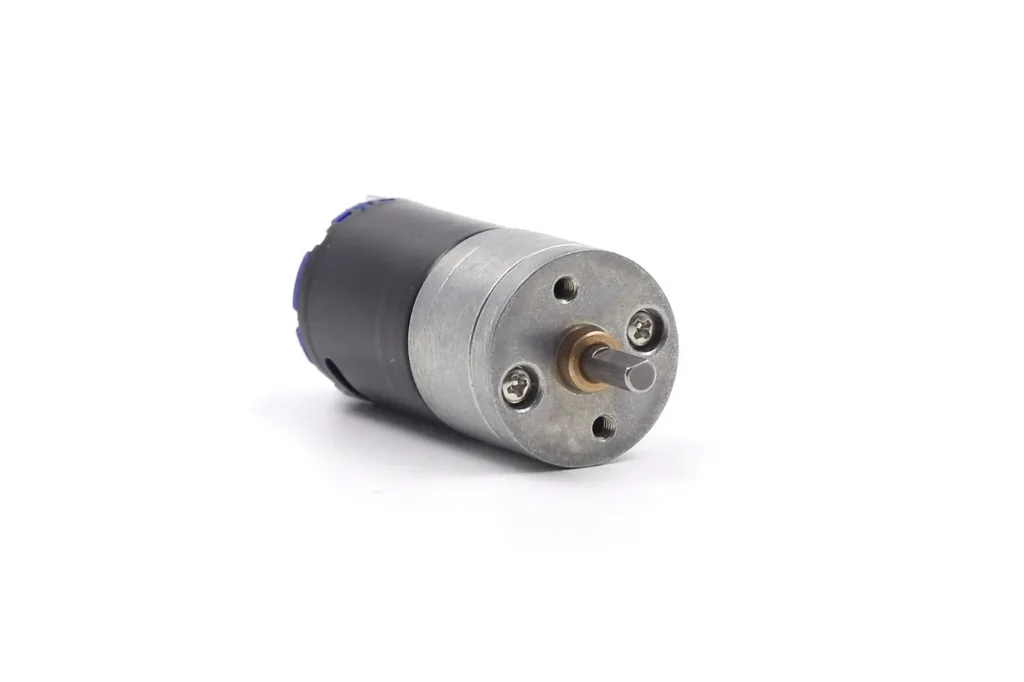
Motor shaft and output shaft are on the same axis (coaxial).
Advantages:
- Simple structure, easy to manufacture
- High efficiency, low friction loss
- Easy to integrate, compact volume
Limitations:
- Strict requirements for installation space, less flexible layout
- Not suitable for special structural needs
Applications:
- Small robots
- Clocks
- Gear pumps
- Compact instrument equipment
Advantages:
- Provides more flexible layout options
- Suitable for special installation spaces
Limitations:
- More complex design and assembly
- May occupy more space than the inline type
Applications:
- Custom-cased equipment
- Side-mounted drive systems
- Automation requiring offset transmission
2.Offset Spur Gear Motor
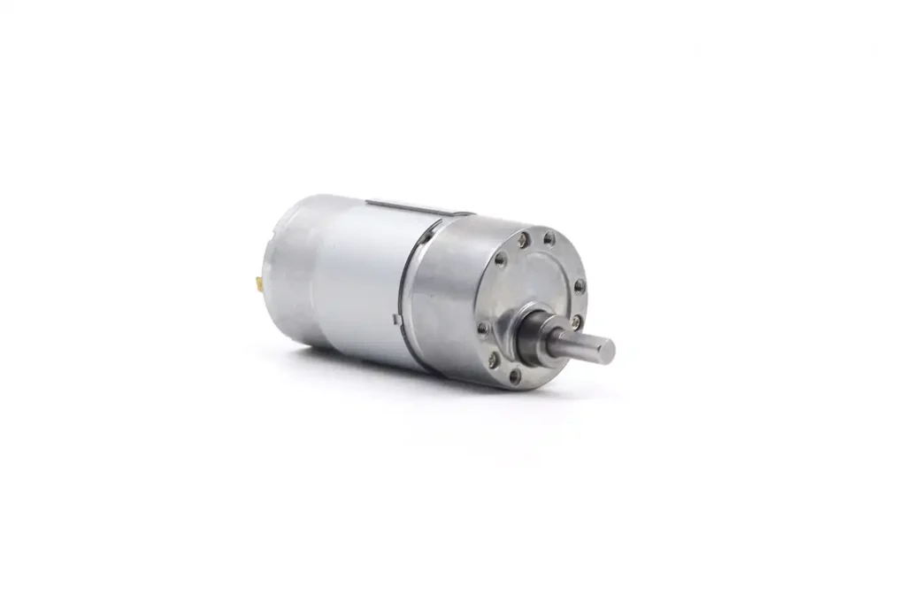
Gear system shifts the output shaft to one side of the motor shaft (parallel but not collinear).
3.Foldback Spur Gear Motor
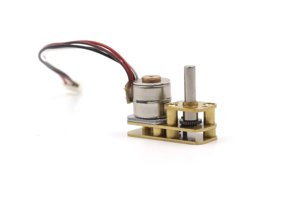
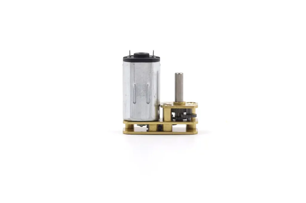
Gear set “folds back” above the motor body, shortening the overall length.
Advantages:
- Space-saving, suitable for length-constrained designs
- Maintains high efficiency and stable transmission of spur gears
- Lightweight, easy for compact integration
- Stable gear ratio, reliable transmission
Limitations:
- More complex internal structure, higher maintenance difficulty
- Slightly higher cost than inline and offset types
- Limited torque capacity compared to planetary or worm gears
- High assembly precision required; slight deviation can cause noise or wear
Applications:
- Micro-robot chassis (extremely compact spaces)
- Embedded systems (limited motor length)
- Portable instruments, handheld devices
- Micro-automation equipment (e.g., slides, micro-actuators)
- Dynamic art installations or applications requiring aesthetic structure
By External Structure (Form Factor)
The physical shape of the gearbox determines where the motor can be mounted within a machine.
Design: The gearbox diameter usually matches the motor diameter standard (e.g., 12mm, 16mm, 25mm, 37mm, 42mm).
Application: These are perfect for tubular spaces or applications where radial space is limited, but axial length is available. Examples include tubular actuators for blinds, power tools, and robotic joints.
1.Cylindrical Geared Motors (Coaxial)
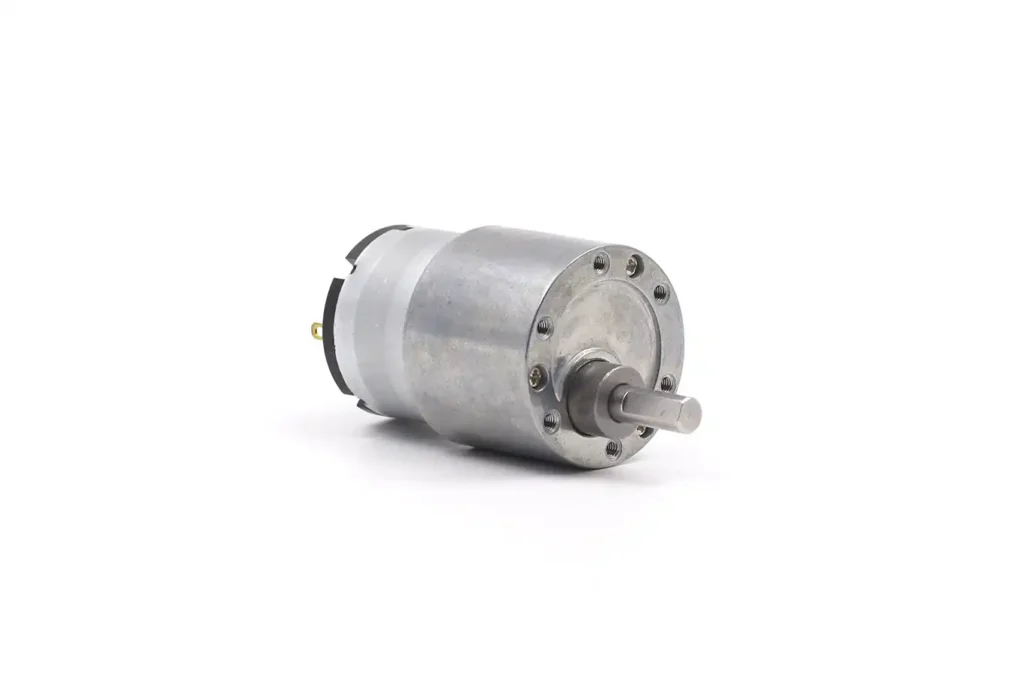
This is the classic configuration where the gearbox is a cylinder extending axially from the motor face.
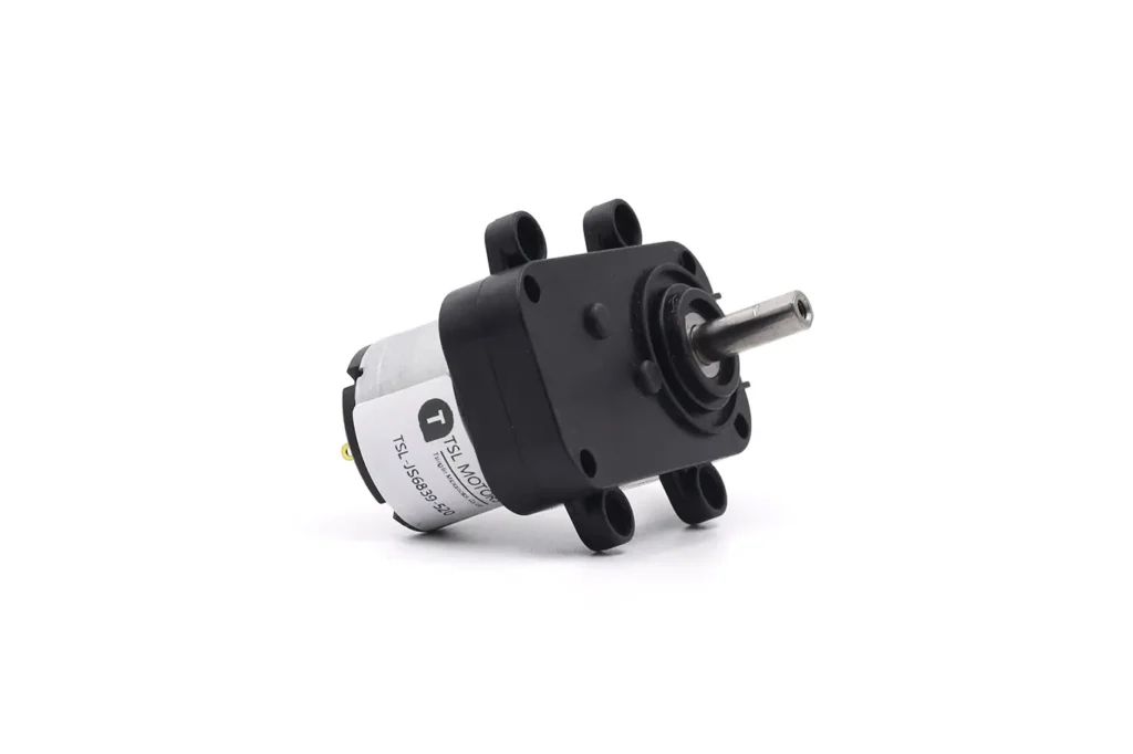
2.Flat/Square Geared Motors (Box Type)
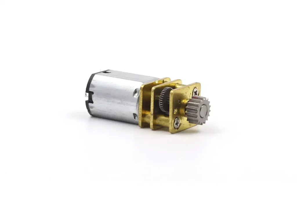
Also known as an “offset” gearbox, this is characterized by a gearbox that is wider and flatter than the motor.
Design: Gears are arranged in a rectangular housing, often resulting in the output shaft being offset from the motor shaft’s axis.
Vending Machine Dominance: This profile is ubiquitous in the vending machine industry. The flat shape allows motors to be tightly stacked side-by-side (e.g., a row of snack spirals), optimizing product density on the shelf.
Mounting: Square gearboxes typically have standardized mounting holes on the face or side, and the shafts are often “D-cut” or hexagonal for direct insertion into the mechanism without set screws, facilitating quick replacement by technicians.
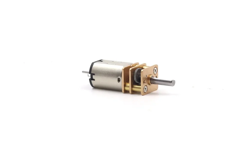
Design: They are extremely compact, typically featuring a 12mm x 10mm cross-section with an exposed metal gearbox casing.
Significance: Due to their surprising torque-to-volume ratio and availability, N20s have become the de-facto standard for micro-robotics, electronic locks, and 3D printing pens. Modern iterations often include an extended rear shaft to accommodate a magnetic encoder, allowing for sophisticated closed-loop control.
3.N20 Miniature Geared Motors
Spur Gear Motor: Advantages and Disadvantages
Spur gear motors are commonly selected because they combine relatively simple construction with flexible speed-reduction options. However, their actual performance depends on the complete gearbox design rather than the use of spur gears alone.
Advantages: Reasons for Selection
Relatively Simple Manufacturing
Straight-tooth gears can be produced by hobbing, shaping, sintering or molding. This gives designers several manufacturing options across different production volumes, gear sizes and material requirements. The resulting gearbox can often be produced and assembled more economically than a comparable precision planetary gearbox.
Potential for High Transmission Efficiency
A properly designed spur gear mesh can transmit power efficiently because it does not rely on the extensive sliding contact found in a worm drive. Nevertheless, spur-gear teeth experience both rolling and sliding during engagement, except near the pitch point.
Complete gearbox efficiency is lower than the efficiency of a single gear mesh and normally decreases as additional reduction stages, bearings and seals are added.
No Gear-Induced Axial Thrust
In an ideal straight spur-gear mesh, the tooth force does not generate the axial thrust associated with helical gears. This can simplify the bearing arrangement, although the shafts and bearings must still support radial gear forces and external output loads.
Flexible Gearbox Layout
Spur gear trains can be arranged as inline, offset, flat, square or foldback gearboxes. This gives designers flexibility when the motor and output shaft cannot share the same axis or when the available installation length is limited.
Usually Backdrivable
Many spur gearboxes can be driven backward from the output shaft, which may be useful for manual adjustment or emergency movement. Backdrivability still depends on total ratio, friction, motor characteristics, external load and whether a brake or locking mechanism is fitted.
Limitations: Engineering Considerations
Noise and Vibration
Straight teeth engage across their face width relatively quickly. At higher speed or load, transmission error and tooth-entry impact can increase vibration and audible gear noise. Material, tooth accuracy, contact ratio, alignment, housing stiffness and lubrication all influence the final noise level.
Limited Torque Density in Some Layouts
A conventional spur gearbox transfers load through one gear mesh at each reduction stage. Achieving substantially higher output torque may require wider gears, larger modules, stronger shafts or a larger housing. A planetary gearbox can often provide greater torque density when several planets share the load effectively.
Accumulated Backlash
Each gear mesh requires operating clearance. In a multistage gearbox, the effects of tooth clearance, shaft movement, bearing play and housing deformation can accumulate at the output. Backlash is therefore a design and manufacturing value, not a fixed characteristic of every spur gear motor.
Additional Stages for High Ratios
A large total reduction ratio usually requires several spur-gear stages. More stages can increase gearbox length, part count, friction, accumulated backlash and manufacturing variation. The highest available ratio is therefore not automatically the best choice.e.
Spur Gear vs Planetary Gear vs Helical Gear vs Worm Gear
The gearbox type influences the output layout, torque density, efficiency, noise, backlash and backdrivability. These characteristics must still be verified from the complete gearbox design because material, accuracy, ratio, number of stages, bearings, lubrication and operating load can change the result.
A spur or helical gear train uses gears whose meshing axes are normally parallel. This does not determine the final position of the output shaft. Depending on the gear arrangement and housing, the output may be coaxial with the motor, offset from it or arranged in a foldback layout.
| Design Factor | Spur Gear Motor | Planetary Gear Motor | Helical Gear Motor | Worm Gear Motor |
|---|---|---|---|---|
| Basic gear arrangement | Straight-tooth gears mesh on parallel axes | Planet gears rotate between a central sun gear and an internal ring gear | Angled teeth mesh progressively, normally on parallel axes | A screw-like worm meshes with a worm wheel |
| Final output position | Can be coaxial, offset or foldback, depending on the gear train | Normally coaxial in the conventional configuration | Can be coaxial, offset or foldback, depending on the gear train | Input and output axes are normally perpendicular and non-intersecting |
| Load transmission | Each stage transfers load through a gear pair; one or more teeth may share the load depending on contact ratio | Several planet branches can share the load when manufacturing and alignment are well controlled | Progressive tooth engagement can increase the effective contact ratio | Sliding contact is a major part of the transmission |
| Torque density | Depends on gear width, module, material, shaft support and housing size | Often high when the planets share load evenly | Depends on tooth geometry, gear width and bearing support | Limited by tooth strength, friction, lubrication and heat dissipation |
| Efficiency tendency | Generally high, but total efficiency decreases with additional stages and losses | Generally high, although multiple meshes and stages add losses | Generally high with suitable alignment and bearing support | Commonly lower because of substantial sliding friction |
| Noise tendency | Noise can increase with speed, load, transmission error and housing resonance | Depends on gear accuracy, planet alignment, stiffness and lubrication | Gradual engagement can reduce excitation compared with an equivalent spur mesh | Can operate smoothly at low speed, but surface condition and lubrication are important |
| Gear-induced axial force | An ideal straight-tooth mesh produces tangential and radial forces without a significant axial component | A conventional spur-tooth planetary stage produces little gear-induced axial force; external output loads still require suitable bearings | Angled teeth generate axial thrust and require appropriate bearing support | The worm and wheel produce axial and radial reactions that must be supported |
| Backdrivability | Often backdrivable, depending on total ratio, friction, motor characteristics and any brake | Often backdrivable, depending on ratio, preload and internal friction | Often backdrivable, depending on ratio and friction | May resist backdriving, but self-locking must be verified under actual conditions |
| Typical design reason | Relatively simple and economical reduction with flexible output positioning | Compact coaxial transmission and high torque density | Smoother engagement where axial loads can be supported | Right-angle transmission or a relatively large ratio in one stage |
When Should Each Gear Motor Be Considered?
Choose a spur gear motor when a relatively simple and economical straight-tooth gear train can meet the required torque, noise, installation space and output-shaft position.
Choose a planetary gear motor when coaxial output and higher torque density are important. The advantage depends on effective load sharing between the planet gears, not simply on the number of planets. See What Is a Planetary Gear Motor? for its structure, ratio and design limits.
Choose a helical gear motor when smoother tooth engagement is valuable and the shafts, bearings and housing can support the resulting axial thrust.
Choose a worm gear motor when the mechanism requires a right-angle output or a relatively large reduction in one stage. Do not assume that every worm drive is self-locking. Backdrivability depends on lead angle, friction, lubrication, wear and external load. See Worm Gearbox: Working Principle, Design & Solutions for the relevant design conditions.
The final decision should be based on the required operating point and mechanical layout rather than a general claim that one gearbox type is always more efficient, quieter or stronger.
Where Are Spur Gear Motors Used?
The theoretical advantages of the spur gear motor translate into specific roles across various industries. We examine four distinct scenarios where the spur gear motor is the dominant solution.
Where Are Spur Gear Motors Used?
Spur gear motors are used in equipment that requires reduced speed and increased torque without the coaxial layout of a planetary gearbox or the right-angle arrangement of a worm drive. The suitability of a spur gearbox depends on the required operating point, installation layout, noise limit, duty cycle and expected service life.
Vending and Dispensing Mechanisms
Vending machines and automatic dispensers commonly require a motor to rotate a spiral, gate, cam or delivery wheel through a controlled movement. A square or flat spur gearbox can fit behind the dispensing channel, while an offset output shaft may simplify connection to the driven mechanism.
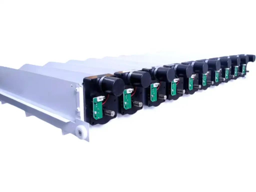
The motor must still be checked against product jams, startup torque and repeated stopping. Output-shaft shape, mounting position, direction of rotation and any position-detection switch should be confirmed from the actual dispensing mechanism.
Mobile Robots and N20 Drives
Compact spur gear motors are frequently used to drive wheels, rollers and small mechanisms in mobile robots. An N20 motor combined with a metal or plastic spur gearbox offers multiple ratios within a small package and can also be equipped with a rear-shaft encoder.
Selection should be based on wheel diameter, vehicle mass, target speed, slope, rolling resistance and acceleration—not on no-load RPM alone. Obstacle impacts or locked wheels can produce high current and gearbox shock loads, so repeated stall operation should be avoided.
For a detailed explanation of N20 configurations, ratios and feedback options, see the N20 Gear Motor Selection Guide.
Conveyors and Automation Equipment
Spur gear motors can drive small conveyors, rollers, indexing mechanisms and packaging equipment where an efficient, backdrivable transmission is useful. Their flexible gear arrangement also allows the output shaft to be positioned according to the available installation space.
For continuous or frequently repeated operation, verify the loaded output speed, continuous torque, motor current, winding temperature and gearbox temperature. Conveyor belt tension and external radial load must also remain within the output-shaft and bearing limits.
Medical and Laboratory Equipment
Spur gear motors may be used in pumps, sample-handling mechanisms, dosing systems and laboratory automation where compact dimensions and controlled motion are required. Plastic gears can reduce mass and gear-mesh noise, while metal gears may be selected where higher load capacity or temperature resistance is needed.
Material suitability cannot be determined from the words “POM,” “PEEK” or “medical grade” alone. Gear material, lubricant, housing, cleaning method and contamination risk must be evaluated against the application’s environmental and regulatory requirements. Noise, output accuracy and service life should be confirmed through testing in the complete device.
How to Size a Spur Gear Motor for an Application
How to Size a Spur Gear Motor for an Application
Spur gear motor sizing should begin with the load and required output motion, not with a preferred motor diameter or catalog ratio. The motor and gearbox must be checked separately because each has different electrical, thermal and mechanical limits.
1. Define the Required Output Motion
Determine the speed and torque required at the gearbox output shaft under actual load.
Record the following:
- Loaded output speed
- Continuous operating torque
- Starting and acceleration torque
- Short-duration peak torque
- Operating time and duty cycle
- Frequency of starting, stopping and reversing
- Load inertia and friction
- External radial and axial loads on the output shaft
Stall torque is the torque produced at zero speed and high current. It is an operating boundary, not a permissible continuous rating or a universal peak-torque specification.
2. Estimate the Required Gear Ratio
Estimate the ratio from the motor speed at the intended operating point:
Required ratio ≈ Motor operating speed ÷ Required output speed
Do not automatically use the motor’s no-load speed. Under load, motor speed decreases as current and torque increase.
After estimating the ratio, verify the number of reduction stages, expected efficiency, gearbox length, backlash and output torque. A higher ratio may require more stages and does not guarantee a more suitable operating point.
3. Verify the Motor and Drive System
Confirm that the motor can produce the required torque without exceeding its continuous current and temperature limits. The power supply, motor driver, connectors and wiring must also tolerate startup and transient current without excessive voltage drop.
Check the voltage directly at the motor terminals while the system is loaded. The power-supply label alone does not confirm the voltage that reaches the motor.
If PWM control is used, verify the driver’s current rating, switching method and thermal performance under the intended duty cycle.
4. Verify the Gearbox Mechanical Limits
The estimated output torque must remain within the gearbox’s specified continuous, intermittent and peak torque limits. These limits may be determined by the gear teeth, shafts, pins, bearings, bushings, output interface or housing—not only by the motor.
Also confirm:
- Gear and housing materials
- Output-shaft dimensions and shape
- Bearing capacity
- Backlash requirement
- Noise limit
- Lubrication and operating temperature
- Dust, moisture and contamination exposure
- Expected service life
A gearbox should not be assigned an IP rating unless the complete assembly has been designed and tested for that rating.
5. Validate the Selected Motor in the Actual Mechanism
Prototype testing should reproduce the most demanding operating conditions, including the lowest supply voltage, highest expected load, frequent starts, reversals and the maximum ambient temperature.
Measure loaded speed, current, motor temperature, gearbox temperature, noise and output behavior. A design margin should be based on load uncertainty, temperature, wear and production variation rather than a universal percentage of stall torque.
Maintenance, Noise Reduction, and Troubleshooting
Many miniature spur gearboxes are lubricated during assembly and designed to operate without routine disassembly. Maintenance requirements depend on whether the gearbox is sealed, serviceable or integrated permanently into the equipment.
Lubrication and Noise Control
Lubrication reduces friction and wear between the gear teeth, shafts, bushings and bearings. However, lubricant selection must consider gear material, load, speed, operating temperature, seal compatibility and environmental requirements.
A high-viscosity grease may reduce some tooth-impact noise, but excessive viscosity or grease quantity can increase drag, startup current and low-temperature resistance. Grease cannot correct inaccurate tooth profiles, gear eccentricity, shaft misalignment, excessive bearing clearance or a flexible housing.
Noise may also come from the motor, bearings, output mechanism or PWM drive rather than the gearbox itself. Before changing the lubricant, determine whether the sound follows motor speed, gear-mesh frequency, load or direction of rotation.
Timken’s lubrication guidance similarly recommends matching grease to load, speed, temperature, water exposure and contamination instead of treating one grease as suitable for every application.
Do not open or add grease to a sealed, lifetime-lubricated gearbox unless the gearbox design specifically permits servicing. Mixing incompatible lubricants can change consistency, reduce lubrication performance or damage plastic and sealing materials.
Common Failure Modes and Troubleshooting
| Symptom | Possible Causes | Recommended Checks |
|---|---|---|
| Abnormal whining or rattling | Gear wear, tooth damage, eccentric gears, misalignment, loose housing, bearing play or unsuitable lubrication | Compare noise under no-load and loaded conditions; inspect mounting, shaft runout and gear condition |
| Output speed is lower than expected | Supply-voltage drop, excessive load, incorrect ratio, high lubricant drag, bearing resistance or damaged gears | Measure voltage at the motor terminals, loaded current and output speed; test the motor after disconnecting the external load |
| Current or temperature increases | Overload, repeated starting, shaft misalignment, bearing damage, excessive grease or gear interference | Check load torque, duty cycle, output-shaft alignment, motor current and stabilized temperature |
| Motion stops or becomes intermittent | Broken or deformed tooth, foreign material, bent shaft, loose gear, housing deformation or driver interruption | Stop operation, rotate the mechanism carefully without power and inspect both the electrical drive and gear train |
| Backlash increases | Tooth wear, shaft or bushing wear, loose output gear, bearing clearance or housing deformation | Measure output movement during controlled direction reversal and compare it with the initial condition |
| Gear teeth fail | Shock load, repeated stall, excessive peak torque, insufficient tooth strength, poor load distribution or material defect | Review startup, jam and reversal loads; inspect the failed tooth and verify the gearbox peak-torque limit |
| Grease leaks or contamination enters | Excessive grease quantity, damaged seal, housing gap, elevated temperature or incompatible lubricant | Inspect the housing and seal, confirm the grease quantity and identify the contamination path |
One damaged plastic gear is not proof that plastic is unsuitable for the application. The failed component may simply be the first part exposed to overload, impact or misalignment. Failure analysis should consider the complete load path before changing the gear material.
A useful maintenance approach is to monitor changes in loaded current, temperature, noise and backlash over time. A gradual change in these values can reveal developing wear or alignment problems before the gearbox stops operating.
👉 If you cannot identify the fault or are unsure which motor replacement to choose, please contact us — we will provide you with the most satisfactory solution.
Conclusion
A spur gear motor uses straight-tooth gears on parallel axes to reduce motor speed and increase available output torque. The final output shaft can be coaxial, offset or foldback depending on the gear arrangement; an offset shaft is not an inherent requirement of spur gearing.
Spur gear motors can provide a relatively simple and economical transmission, but their performance must be evaluated at the actual operating point. Ratio, number of stages, gearbox efficiency, continuous and peak torque limits, backlash, noise, shaft loading, lubrication and temperature should all be verified before the design is finalized.
Frequently Asked Questions
Is the output shaft of a spur gear motor always offset?
No. Only the axes of each meshing spur-gear pair must be parallel. By arranging several gear stages differently, the final output shaft can be coaxial with the motor, offset from it or placed in a foldback layout.
Can a spur gear motor hold a load when power is off?
Not reliably by default. Many spur gearboxes are backdrivable, so an external load may rotate the output shaft when power is removed. Applications that must hold position may require a brake, mechanical lock or another verified holding mechanism.
Does a higher gear ratio always provide more usable torque?
A higher ratio increases theoretical output torque, but usable torque is limited by gearbox efficiency, motor temperature, gear strength, shafts, bearings and the gearbox’s rated torque. Adding stages can also increase losses and backlash.
Why does a spur gear motor become noisy?
Possible sources include tooth-entry impact, transmission error, gear eccentricity, excessive backlash, worn bearings, poor alignment, housing resonance and unsuitable lubrication. The motor, PWM drive and external mechanism can also contribute to the measured sound.
Should I choose plastic or metal gears?
Choose according to the load, speed, temperature, noise target, service life and operating environment. Plastic gears can reduce mass and meshing noise, while metal gears can provide greater strength and temperature resistance. A mixed-material gear train may also be appropriate when different stages have different requirements.
TSL Motor Spur Gear Motor Solutions
TSL Motor supplies spur gear motors combined with brushed DC, brushless DC, coreless and stepper motors. Depending on the application, the gearbox can be configured with different ratios, gear materials, output-shaft positions, shaft shapes, bearings or bushings, encoders, windings, cables and connectors.
For an initial engineering review, please provide:
- Required voltage
- Loaded output speed
- Continuous and peak torque
- Operating time and duty cycle
- Available installation dimensions
- Output-shaft position, dimensions and external loads
- Noise and backlash requirements
- Operating temperature and environment
- Encoder or control requirements
View our available spur gear motor configurations or contact TSL Motor to discuss a standard or customized solution.
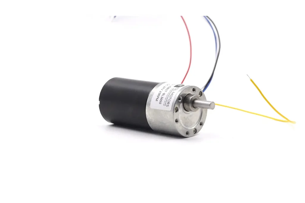
Spur Gear Motor
TSL Motors provides compact and reliable spur gear motors designed for cost-efficient performance. Our motors meet a wide range of application needs with various reduction ratios, voltages, sizes, and precision gear options, including steel or brass gears.