Published: DECEMBER 2, 2025
Updated:SEPTEMBER 13, 2026
A 12V rating only identifies the motor’s intended supply voltage. It does not tell an engineer how fast the motor will run under load, how much continuous torque it can deliver, how much current it needs during startup, or how long it can operate before reaching its thermal limit. Two motors marked 12V can therefore have very different winding resistance, speed, current and torque characteristics.
Motor selection should begin at the load, not with the voltage label. The required loaded speed, continuous torque, acceleration or peak torque, duty cycle, available current and operating temperature must first be defined. The motor, gearbox, driver and power supply can then be evaluated as one system.
This guide explains how to compare brushed, coreless, brushless and geared 12V motors using their actual operating parameters. It also uses a TSL 12V N20 gear motor data table to show how gearbox ratio changes output speed and torque without changing the motor’s nominal supply voltage.
Key Takeaways
- A 12V rating defines voltage, not actual motor performance.
- Start selection with loaded speed, continuous torque and duty cycle.
- Use rated torque for continuous operation; stall torque is only a limit.
- Verify startup current and voltage drop instead of relying on fixed estimates. A
- gearbox increases usable torque but adds losses, backlash and mechanical limits.
- Confirm the final choice with a sample and loaded temperature test.
What Does “12V DC Motor” Actually Tell You?
A 12V DC motor is designed to operate from a nominal 12V supply, but the voltage label alone does not define its speed, torque or current. Those values depend on the winding, motor size, commutation structure and mechanical load.
In practice, 12V is popular because compatible batteries, adapters, drivers and automotive power systems are widely available. It is convenient for prototypes and compact equipment, but it is not automatically safer, stronger or more efficient than a 6V or 24V motor.
I treat 12V as a system constraint rather than a performance specification. After confirming the available supply, the next step is to compare the required operating point with the appropriate DC motor construction.
Which Type of 12V DC Motor Fits the Application?
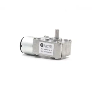
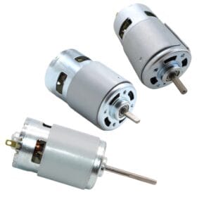
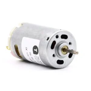
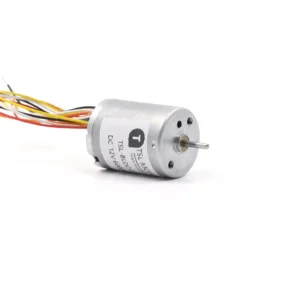
Brushed, brushless, coreless and geared motors are often listed as parallel choices, but they describe different aspects of motor design. Brushed and brushless refer to the commutation method; coreless refers to the rotor or winding construction; a gear motor combines a motor with a transmission.
Understanding this distinction prevents an early selection mistake: choosing a motor by its category name without checking how the complete drive system behaves under load.
| Motor configuration | Main advantage | Engineering limitation | Suitable starting point |
|---|---|---|---|
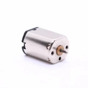
| Brushed DC motor | Simple two-wire operation and low controller cost | Brush wear, electrical noise and limited service life | Cost-sensitive or intermittent-duty equipment |
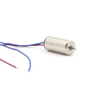
| Coreless DC motor | Low rotor inertia and fast acceleration | Lower thermal capacity and sensitivity to prolonged overload | Fast-response, compact or precision motion |
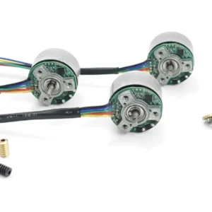
| Brushless DC motor | Long service life and efficient electronic commutation | Requires a compatible driver and correct Hall or sensorless control | Continuous-duty and high-cycle applications |
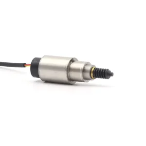
| DC gear motor | Converts motor speed into usable low-speed output torque | Adds efficiency loss, backlash and gearbox torque limits | Loads operating below the motor’s practical speed range |
Brushed, Coreless or Brushless?
A brushed iron-core motor is often sufficient when cost and simple control are more important than operating life. A coreless motor is more suitable when low inertia and rapid acceleration matter, but its lower thermal mass makes current control important.

A brushless motor becomes more attractive when the application has long operating hours, frequent cycles or difficult maintenance access. However, the driver must match the winding, Hall configuration, voltage and peak current requirements.
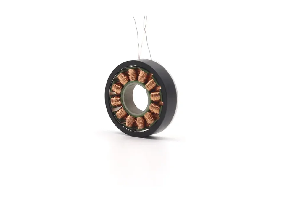
Coreless and brushless are not opposites. A coreless motor may use either brushed or brushless commutation, so both construction and control method should be confirmed in the specification.
When Is a Gearbox Necessary?
A gearbox is normally required when the load speed is much lower than the efficient operating speed of the motor. It reduces output speed and increases available output torque, but the final output is still limited by gearbox efficiency, rated torque, backlash and bearing capacity.
The more reliable sequence is to select a motor that can provide the required power and thermal performance, and then determine the gearbox type and ratio. A large ratio cannot compensate for an undersized motor or an unsuitable duty cycle.
12V DC Motor:Key Parameters
A motor datasheet should be read as a set of connected operating parameters. Voltage, speed, torque and current cannot be evaluated separately, and no-load speed should never be treated as the expected working speed.
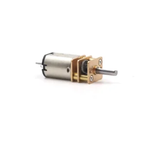
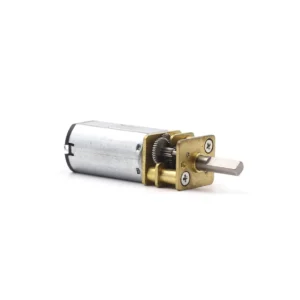
The following TSL-GM12-N20-KVA data shows how different gearbox ratios change the output characteristics of the same 12V gear motor platform.
TSL-GM12-N20-KVA,12V DC, Parameters
| Ratio | No Load | Rated Load | Stall | ||||
| i : 1 | Current | Speed | Current | Speed | Torque | Current | Torque |
| 10:1 | ≤55mA | 2150rpm | ≤0.2A | 1450rpm | 50g.cm | ≤0.5A | 0.13kg.cm |
| 20:1 | ≤55mA | 1075rpm | ≤0.2A | 720rpm | 100g.cm | ≤0.5A | 0.26kg.cm |
| 30:1 | ≤55mA | 717rpm | ≤0.2A | 480rpm | 150g.cm | ≤0.5A | 0.39kg.cm |
| 50:1 | ≤55mA | 430rpm | ≤0.2A | 290rpm | 250g.cm | ≤0.5A | 0.7kg.cm |
| 100:1 | ≤55mA | 215rpm | ≤0.2A | 145rpm | 500g.cm | ≤0.5A | 1.3kg.cm |
| 150:1 | ≤55mA | 143rpm | ≤0.2A | 95rpm | 750g.cm | ≤0.5A | 2.0kg.cm |
| 210:1 | ≤55mA | 102rpm | ≤0.2A | 70rpm | 1000g.cm | ≤0.5A | 2.7kg.cm |
| 298:1 | ≤55mA | 72rpm | ≤0.2A | 48rpm | 1500g.cm | ≤0.5A | 3.0kg.cm |
| 380:1 | ≤55mA | 57rpm | ≤0.2A | 38rpm | 1900g.cm | ≤0.5A | 3.0kg.cm |
| 1000:1 | ≤55mA | 21rpm | ≤0.2A | 14rpm | 3000g.cm | ≤0.5A | 3.5kg.cm |
What Does This Table Show?
At 10:1, the rated output is 1,450 rpm and 50 g·cm. At 100:1, the rated speed falls to 145 rpm while rated torque rises to 500 g·cm. This is the expected speed–torque conversion produced by the gearbox.
However, output torque does not continue increasing perfectly in proportion to the ratio. Gear-mesh losses increase with additional stages, while the gears, shafts, bearings and housing impose mechanical limits. This is why the 1,000:1 version is rated at 3,000 g·cm rather than ten times the torque of the 100:1 version.
The table also uses different torque units:
1 kg·cm = 1,000 g·cm
1 kg·cm ≈ 0.0981 N·m
Rated torque and stall torque must therefore be converted to the same unit before comparison.
A useful first estimate is:
Output speed ≈ Motor speed ÷ Gear ratio

Output torque ≈ Motor torque × Gear ratio × Gearbox efficiency
These formulas are useful for early selection, but the published gearbox torque limit still takes priority. For a deeper explanation of speed, current, torque and efficiency curves, see How to Read a DC Motor Performance Curve.
Which Specifications Define the Real Operating Point?
The correct motor is not the one with the highest individual specification. Speed, torque, current and temperature must be checked at the same operating point.
Loaded Speed and Continuous Torque
Motor speed falls as load torque increases. No-load speed is useful for comparing windings, but the rated or loaded speed is more relevant to the application.
Motor torque is approximately related to current:
Torque ≈ Torque Constant × Current
T ≈ Kt × I
Continuous torque is limited mainly by winding temperature and heat dissipation. Peak torque may be available during acceleration or a short load increase, while stall torque represents a zero-speed limit and should not be used as a continuous rating.
Startup Current and Driver Capacity
At startup, motor speed and back EMF are initially close to zero, so current can rise quickly. The actual peak depends on winding resistance, motor inductance, wiring resistance, power-supply impedance and driver current limiting.
For this reason, a fixed rule such as “startup current is always two to five times rated current” is only an estimate. A current-regulated driver can deliberately limit the peak. Texas Instruments’ DRV8874 motor-driver documentation provides an example of integrated current sensing, current regulation and protection functions.
The driver should be checked for:
- Operating voltage range;
- Continuous and peak output current;
- Current-limiting method;
- Overcurrent and overtemperature protection;
- PWM frequency and control interface.
Power, Efficiency and Temperature
Electrical input and mechanical output are different quantities:
Electrical input power: Pin = V × I

Mechanical output power: Pout = T × ω

Efficiency: η = Pout ÷ Pin
The difference becomes heat in the winding, brushes, bearings, driver and gearbox. A motor may satisfy the required torque for several seconds but still be unsuitable for continuous operation if its temperature continues rising.
In practice, the safer limit is the operating point that keeps the winding, housing, bearings and gearbox within their permitted temperatures throughout the required duty cycle.
How to Select a 12V DC Motor Step by Step
Define the Load-Side Motion
Start with the mechanism rather than the motor catalogue. Record:
- Required output speed;
- Continuous load torque;
- Startup or acceleration torque;
- Direction and reversal frequency;
- Continuous or intermittent duty;
- Available installation space.
For a rotating arm or pulley:
Load torque = Force × RadiusFriction, acceleration and external disturbances should be added separately rather than hidden inside an arbitrary safety factor.
Separate Continuous and Peak Requirements
One torque value is rarely enough. Continuous torque determines temperature rise, while peak torque covers startup, acceleration, impact or short load changes.
The motor should remain within its continuous thermal capability during normal operation and provide the required peak torque without exceeding the motor, driver or gearbox limits.
Match Loaded Speed and Gear Ratio
Select the motor from its loaded speed, not its no-load speed. If the required output speed is much lower, estimate the gearbox ratio from the motor speed at the intended operating point.
Then verify:
- Gearbox efficiency;
- Continuous and peak output-torque limits;
- Backlash;
- Output-shaft radial and axial loads;
- Required lifetime.
For a detailed comparison of gearbox structures, see the DC Gear Motor Selection Guide.
Check the Complete Electrical Path
The power supply, driver, connectors and wiring must support the motor together. Check the voltage at the motor terminals during startup and maximum load, not only at the power-supply output.
The driver must support the required continuous current, controlled peak current, PWM method and rotation direction without excessive voltage drop or overheating.
Validate the Real Load Cycle
The final decision should be based on a representative sample. Test startup, loaded speed, current, reversal, housing temperature and noise under the actual operating cycle.
A short no-load test cannot confirm continuous-duty performance. The most useful result is whether the motor reaches a stable temperature while completing the required movement reliably.
How Do 12V Motor Requirements Change by Application?
The same 12V motor can behave very differently in a pump, lock or robot. The voltage remains unchanged, but the load cycle and dominant selection risk are different.
| Application | Main operating requirement | Common selection risk |
|---|---|---|
| Door locks and latches | Short movement, reliable startup and defined end position | Selecting from running torque while ignoring initial friction or jamming |
| Pumps and blowers | Stable loaded speed and continuous thermal performance | Selecting from no-load RPM without testing the actual fluid or airflow load |
| Mobile robots | Continuous wheel torque, acceleration torque and bidirectional control | Insufficient battery or driver current during simultaneous motor startup |
| Lifters and linear actuators | Screw force, travel speed, holding method and limit protection | Using stall current as the normal stopping method |
| Medical and laboratory equipment | Predictable motion, low noise and repeatable service life | Evaluating only motor noise while ignoring gearbox, mounting and structure-borne vibration |
For locks and actuators, the highest torque often occurs during startup or near the end of travel. Pumps and blowers are usually more sensitive to loaded speed and continuous temperature. Mobile robots require both steady driving torque and short acceleration torque.
The motor should therefore be selected from the application’s complete operating cycle, not from a generic list of industries.
How Should a 12V DC Motor Be Powered and Controlled?
A 12V motor should not be matched to a power supply by voltage alone. The supply and driver must also support continuous current, controlled startup current and the required direction or speed-control method.
| Motor system | Minimum control requirement |
|---|---|
| Brushed motor, one direction | 12V switching circuit with current and transient protection |
| Brushed motor, forward and reverse | H-bridge driver |
| Brushed motor with speed control | PWM-capable H-bridge |
| BLDC motor | Compatible electronic commutation driver |
| Closed-loop speed or position control | Motor driver, encoder feedback and controller |
Check Voltage at the Motor Terminals
Under load, the voltage reaching the motor is approximately:
Motor voltage = Supply voltage − Wiring drop − Connector drop − Driver dropVoltage loss increases with current. A system may measure 12V without load but fall well below 12V during startup, causing slow acceleration, controller reset or failed operation.
Size Current from the Load Cycle
The supply must support normal operating current without overheating and provide enough transient current for startup and acceleration. However, it does not always need to deliver the motor’s full theoretical stall current if the driver intentionally limits current and the motor can still start the load.
The most common mistake is choosing a supply from rated current alone while ignoring startup, simultaneous motor operation and cable losses.
Use Protection Appropriate to the Failure Mode
A practical drive system may require:
- Current limiting;
- Stall timeout;
- Overtemperature protection;
- Reverse-polarity protection;
- Fuse or electronic circuit protection;
- Limit switches for end-of-travel mechanisms.
For actuators and locks, holding the motor continuously at stall is generally a poor control strategy. A limit switch, current threshold, position feedback or mechanical holding method should stop or reduce the current after the movement is completed.
When Should a 24V Motor Be Considered Instead?
A 12V system is convenient, but it should not be treated as the correct voltage for every power level. For the same electrical input power:
Power = Voltage × CurrentIncreasing the system voltage can reduce the current required to transfer the same power. This may reduce cable, connector and driver losses, particularly in equipment with longer wiring or higher continuous power.
A 12V motor remains a practical choice when:
- The machine already uses a regulated 12V supply;
- Required mechanical power is relatively low;
- Battery, automotive or accessory compatibility is important;
- Short wiring keeps voltage drop manageable.
A 24V system may be more suitable when:
- Continuous current at 12V becomes too high;
- Wiring distance or connector heating is a concern;
- The equipment already has a 24V control bus;
- Higher continuous mechanical power is required.
A 24V motor is not automatically more efficient than a 12V motor. Efficiency still depends on winding design, operating point, driver and cooling. A 12V winding should also not be connected directly to 24V unless the motor and control method have been specifically evaluated for it.
For a more detailed comparison, see 12V vs 24V High-Torque DC Motor Selection
Conclusion
Selecting a 12V DC motor begins with the load-side operating point, not the voltage label. Loaded speed, continuous torque, peak torque and duty cycle determine the motor requirement, while the power supply and driver determine whether that performance can actually be delivered.
When a gearbox is used, its ratio, efficiency, backlash and mechanical torque rating must be included in the calculation. Higher reduction does not automatically produce a better drive system, especially when additional stages increase loss or the gearbox reaches its load limit.
The final 12V DC motor selection should be verified with a representative sample under the real startup, load and temperature cycle. A motor that operates correctly for a short no-load test may still be unsuitable for continuous production use.
12V DC Motor FAQ
Q1:Can a 12V DC motor be connected directly to a 12V battery?
A brushed motor can rotate when connected directly, but this provides no speed control, current limiting or reversal protection. A suitable switch or H-bridge driver is normally required. A BLDC motor must use an electronic commutation driver.
Q2:hy does a 12V motor fail to start even though the supply measures 12V?
The supply may show 12V without load but drop during startup. Common causes include insufficient peak current, long or thin wires, connector resistance, driver voltage drop and excessive mechanical load. Measure the voltage directly at the motor terminals while starting.
Q3:How much current does a 12V DC motor need?
There is no standard current for all 12V motors. Check no-load, rated and stall current for the selected winding. The power supply must support continuous operating current and the permitted startup or acceleration current.
Q4:Can PWM be used to run a 12V motor from a 24V supply?
A 50% duty cycle does not automatically make 24V safe for every 12V motor. Current ripple, switching frequency, startup conditions, driver regulation and insulation limits must be considered. Use this approach only when the motor and controller have been evaluated together.
Q5:Can a 12V DC motor run continuously?
Yes, if the operating torque, current, cooling and ambient temperature remain within the motor’s continuous rating. A motor capable of producing the required torque briefly may still overheat during continuous operation.
-
 Custom Micro Motors13 products
 - DC Gear Motor173 products
- 6mm Planetary Gear Motor4 products
- 6mm Planetary Metal Gear Motor3 products
- Brushless Gear Motor42 products
- Micro Gear Motor96 products
- Coreless Gear Motor40 products
- N20 Gear Motor26 products
- Plastic Gearbox Motor9 products
- Standard Gear Motor15 products
- Stepper Gear Motor17 products
-
- Planetary Gear Motor59 products
- Spur Gear Motor63 products
- Worm Gear Motor39 products
-
- DC Motor84 products
- Brushed DC Motor17 products
- Brushless DC Motor37 products
- Inrunner Rotor BLDC Motor8 products
- Outrunner Rotor BLDC Motor26 products
-
- Coreless DC Motor17 products
- Micro DC Motor16 products
-
- Dexterous Hand Drive Module28 products
- Micro Linear Actuators13 products
- Stepper Motor32 products
- Micro Stepper Motor13 products
- NEMA Stepper Motor9 products
- Stepper Motor Linear Actuator11 products
-
- Vibration Motors76 products
- Brushless Vibration Motor8 products
- Coin Vibration Motor24 products
- Coreless Vibration Motor3 products
- Encapsulated Vibration Motor6 products
- Linear Resonant Actuator17 products
- Powerful Vibrating Motor17 products
- SMD Vibration Motor4 products
- Sonic Vibration Motor2 products
-