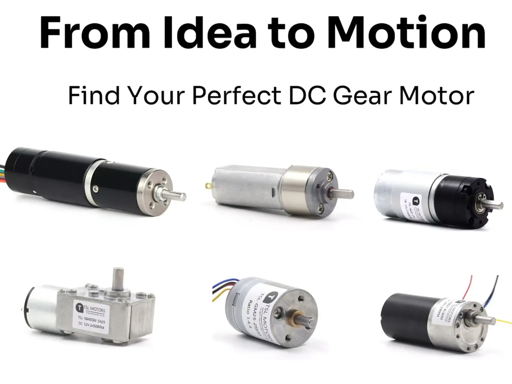
Published: NOVEMBER 10, 2025
Updated: August 28, 2026
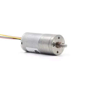
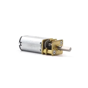
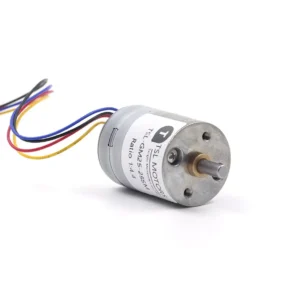
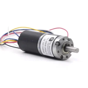
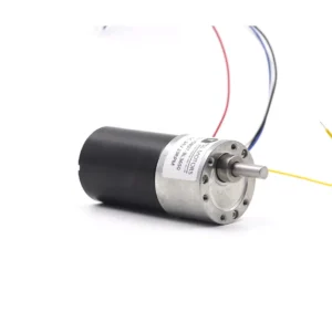
From automotive windows and smart locks to laboratory automation and robotic joints, DC gear motors provide controlled motion when a standalone motor would rotate too quickly or deliver insufficient output torque. Their compact combination of electrical drive and mechanical reduction makes them useful in systems that require lower speed, higher torque and predictable movement.
A DC gear motor combines a direct-current motor with a gearbox. The motor produces high-speed rotation, while the gearbox reduces the output speed and multiplies the available torque. However, the gearbox does not create power: friction in the gears, bearings and seals means that actual output depends on the reduction ratio, gearbox efficiency, motor operating point and applied load.
This guide explains how DC gear motors work, how motor and gearbox types affect performance, and how to interpret voltage, speed, torque, current and efficiency data. It also highlights practical selection mistakes that basic catalog comparisons often miss, including reliance on no-load speed, misuse of stall torque, gearbox torque limits, startup current and duty cycle.
For available sizes, motor technologies and gearbox configurations, explore our DC gear motor product range.
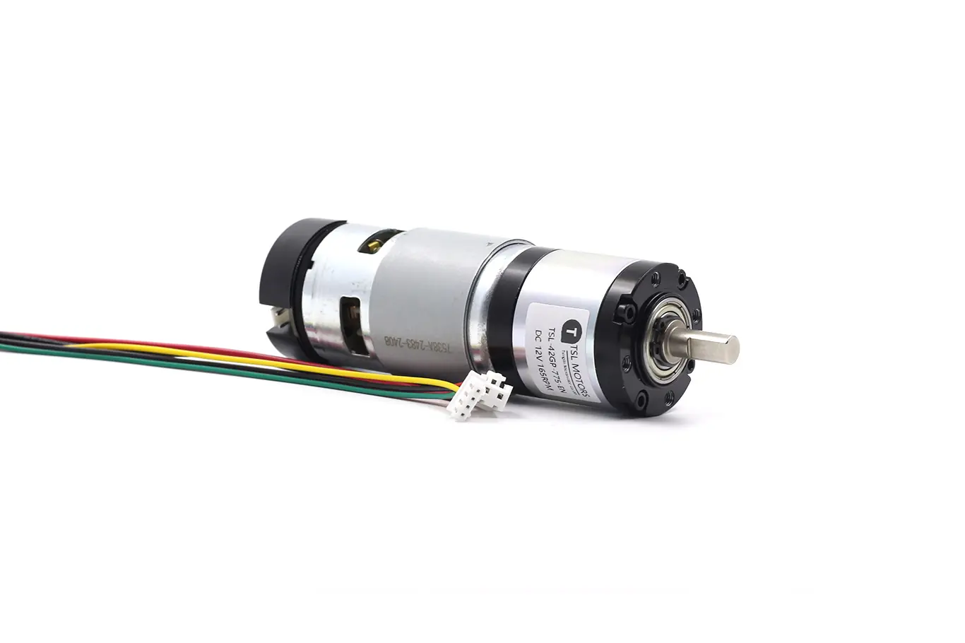
Key Takeaways
- A DC gear motor combines a motor and gearbox to produce a lower output speed and higher usable torque, but gearbox losses mean that output power is lower than the motor’s mechanical input power.
- Selection should begin with the required output speed, continuous torque, peak torque and duty cycle—not with motor diameter, no-load RPM or stall torque alone.
- Motor construction and gearbox structure are separate decisions. Brushed or brushless commutation, iron-core or coreless construction, and spur, planetary or worm gearing affect different aspects of performance.
- Gear ratio can be used to estimate output speed and torque, but the result must include gearbox efficiency and remain below the gearbox’s permissible continuous and peak torque limits.
- Rated speed, torque and current describe a specified operating point. Stall torque and stall current are short-term limits and must not be treated as continuous ratings.
- The power supply and motor driver must tolerate startup, acceleration and transient current without excessive voltage drop. Temperature, airflow and duty cycle also affect the torque available in continuous operation.
- Final selection should be verified under the actual load through startup, reversal, current, temperature, noise and output-shaft load testing before volume production.
Core Principle: Trade Speed for Torque
A standalone DC motor often operates efficiently at a speed much higher than the mechanism requires. Connecting the load directly to the motor may therefore provide excessive speed but insufficient torque, especially during startup, acceleration or changes in load.
A reduction gearbox allows the motor to operate at a more suitable speed while delivering lower speed and higher torque at the output shaft.
Why is reduction needed?
Many small DC motors rotate at several thousand revolutions per minute, while applications such as smart locks, robotic joints, pumps and positioning mechanisms require much lower output speeds. The gearbox matches the motor’s operating range to the speed and torque required by the mechanism.
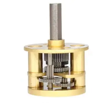
The existing internal-gear image can remain here.
What the gearbox does?
The gearbox transfers mechanical power through one or more gear stages. As the output speed decreases, the available output torque increases according to the reduction ratio.
However, a gearbox does not create mechanical power. Friction between gear teeth, bearings, seals and lubricant converts part of the input power into heat. Output mechanical power is therefore lower than the mechanical power entering the gearbox.
Gear reduction ratio
The reduction ratio describes the relationship between motor speed and output-shaft speed:
Reduction ratio (i) = Motor speed ÷ Output speed
For example, with a 10:1 ratio, the motor turns approximately ten revolutions for each revolution of the output shaft.
The initial output values can be estimated as:
Output speed ≈ Motor speed ÷ Reduction ratio
Output torque ≈ Motor torque × Reduction ratio × Gearbox efficiency
For load-side torque, output-speed and reduction-ratio calculations, see How to Calculate DC Gear Motor Torque and Speed.
These equations are useful for preliminary sizing, but they do not confirm that the selected gearbox can safely transmit the calculated torque. The estimated result must also remain within the gearbox manufacturer’s permissible continuous and peak output-torque limits. The same calculation method is demonstrated in Pittman’s motor and gearbox selection guide.
Real-world efficiency
Gearbox efficiency is not one fixed value that applies to every operating condition. It varies with gearbox type, number of stages, ratio, load, speed, lubrication, temperature, gear material and manufacturing quality.
Adding reduction stages usually increases the available ratio but also introduces additional friction. Use the efficiency stated for the actual gearbox and ratio whenever it is available. If only maximum efficiency is provided, treat it as an estimate rather than a guaranteed value across the complete load and temperature range.
The existing performance-curve image can remain below this explanation.
Choosing the reduction ratio
Begin with the required output speed and estimate the ratio from the motor speed at the intended operating point—not automatically from its no-load speed. Then calculate the motor torque needed to produce the required output torque after gearbox losses.
Before confirming the ratio, check:
- Motor current and temperature at continuous load
- Startup and acceleration torque
- Gearbox continuous and peak torque limits
- Gearbox efficiency for the selected ratio
- Duty cycle and frequency of starting or reversing
- Backlash, noise and backdrivability requirements
A ratio that is too low may leave the motor overloaded or unable to start the mechanism. A ratio that is unnecessarily high may reduce output speed, require additional gear stages and increase losses, backlash or cost.
Types of DC Gear Motor
A geared drive can be classified by motor technology and gearbox structure. These are separate decisions: commutation affects control and service life, rotor construction affects inertia and dynamic response, while the gearbox determines reduction ratio, output layout and mechanical load capacity.
By DC Motor Type
Brushed DC Gear Motor
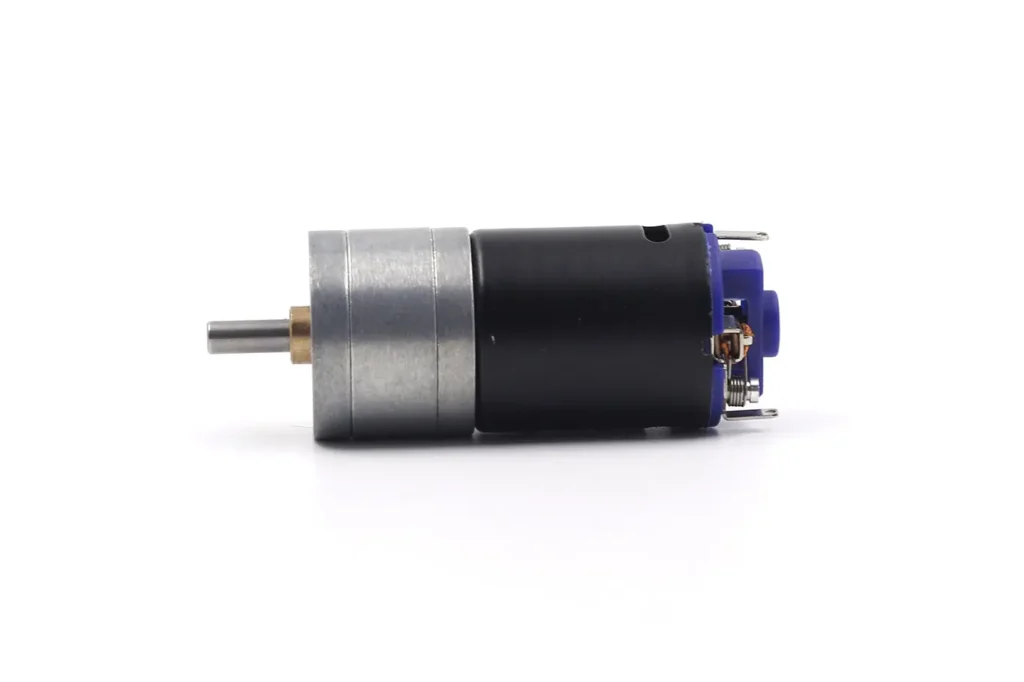
A brushed gear motor uses brushes and a commutator to switch current through the rotating armature. It can run from a suitable DC supply and is straightforward to control using voltage or PWM, but brush wear, commutator condition, current, speed and duty cycle limit service life.
See our explanation of brushed DC motor construction and commutation.
Brushless DC (BLDC) Gear Motor
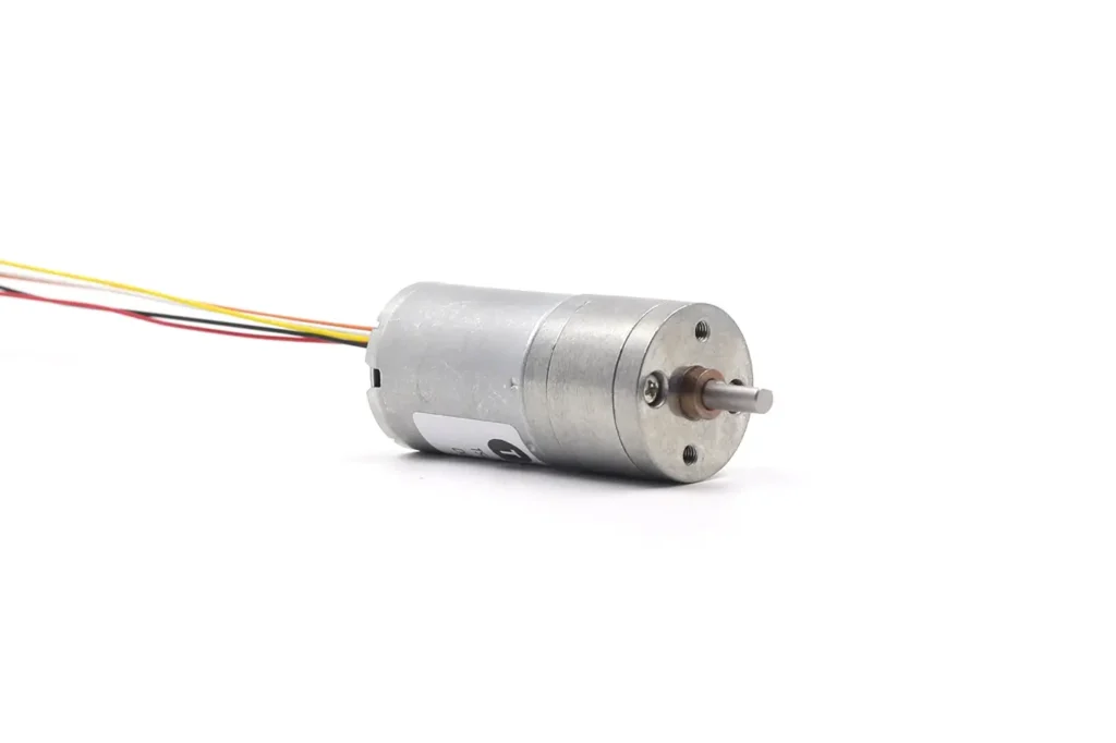
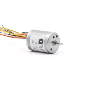
A brushless gear motor uses electronic commutation instead of brushes. Permanent magnets are normally located on the rotor, while the controller switches current through the stator windings according to rotor position. It removes brush wear but requires a compatible controller, and its final performance depends on the motor, gearbox and drive electronics as one system.
Our brushed and brushless motor comparison explains when each technology is appropriate.
Coreless DC Gear Motor
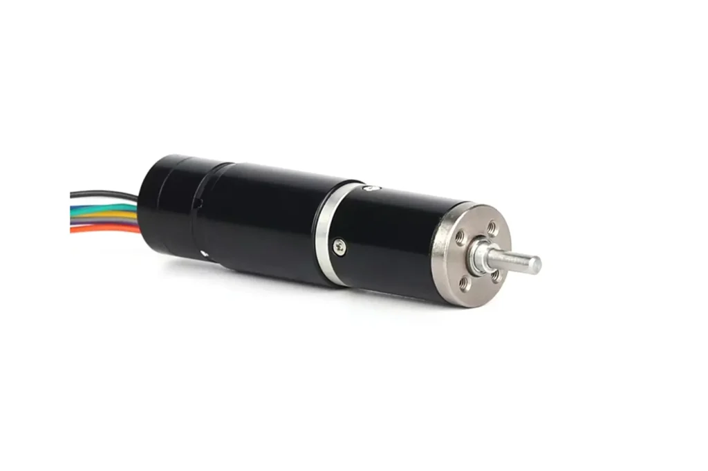
Coreless describes the winding and magnetic construction, not the commutation method. In a conventional brushed coreless motor, the rotor winding forms a lightweight self-supporting cylinder without a laminated iron core. The resulting low inertia supports fast acceleration and smooth motion, but continuous torque remains limited by winding temperature and heat dissipation.
Available brushed and brushless designs can be found in our coreless gear motor range.
Stepper Gear Motor

A stepper gear motor uses a pulse-driven stepper motor with a reduction gearbox. It is useful for low-speed incremental motion and holding applications, but open-loop systems can miss steps when acceleration or load torque exceeds the available torque. Holding torque normally requires winding current, while the gearbox adds reduction, output torque and mechanical backlash.
See the geared stepper motor guide for further details.
By Gearbox Structure
The gearbox determines the output-shaft arrangement, reduction range, torque capacity, efficiency, backlash and backdrivability. These characteristics depend on the complete design, including the number of stages, gear material, bearings, lubrication and manufacturing accuracy.
Spur gear gearbox (parallel-shaft)
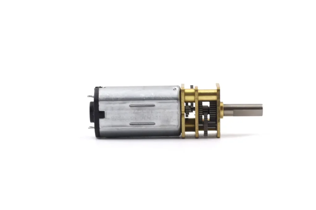
A spur gearbox uses straight-cut gears on parallel shafts. Its relatively simple construction supports efficient transmission, economical production and a wide range of motor combinations. Higher ratios normally require additional stages, increasing length, friction and accumulated backlash.
Explore available spur gear motor configurations.
Planetary gearbox (coaxial)
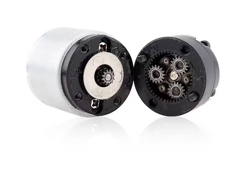
A planetary gearbox uses a central sun gear, planet gears, a ring gear and a planet carrier. Its coaxial layout and load sharing between multiple planets provide high torque density in a compact diameter. Efficiency, backlash and noise depend on the number of stages, gear accuracy, bearing support and assembly quality.
See our planetary gear motor range.
Worm gear gearbox (right-angle output)
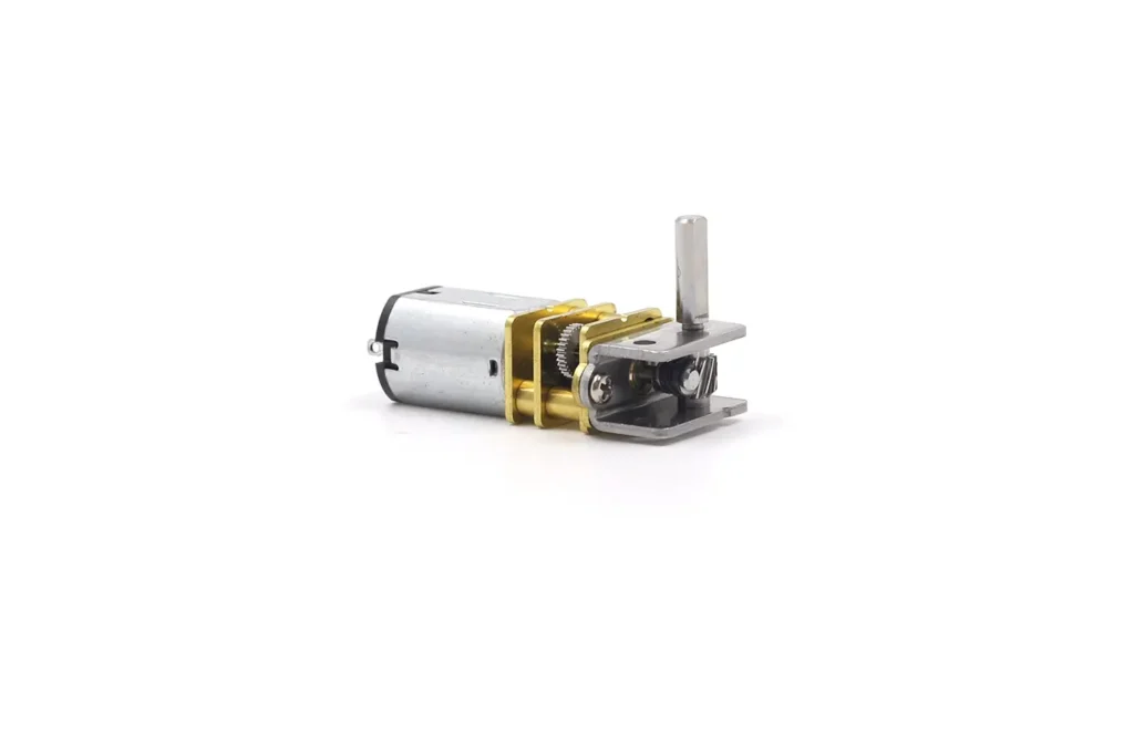
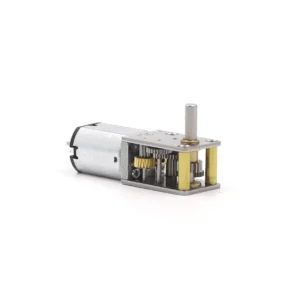
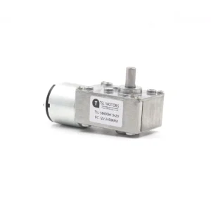
A worm gearbox uses a screw-like worm meshing with a worm wheel, normally producing a 90-degree output. It can provide a large reduction in a compact right-angle layout, but sliding contact generates more friction and heat than rolling gear contact.
A worm gearbox should not automatically be described as self-locking. Backdrivability depends on lead angle, ratio, friction, lubrication, wear and external load, so holding performance must be tested in the actual mechanism.
See DC Worm Gear Motor: Principles, Self-Locking & Selection for a detailed explanation.
Planetary gearbox’s coaxial layout supports compact and neat line layouts. So, the gearbox type should be chosen early in design—it’s about the architecture, not just a component.
To help comparison, here is a table of the main traits of the three common gearbox types:
By Gearbox Structure
The gearbox determines the output-shaft arrangement, reduction range, torque capacity, efficiency, backlash and backdrivability. These characteristics depend on the complete design, including the number of stages, gear material, bearings, lubrication and manufacturing accuracy.
Spur Gearbox (Parallel-Shaft)
A spur gearbox uses straight-cut gears on parallel shafts. Its relatively simple construction supports efficient transmission, economical production and a wide range of motor combinations. Higher ratios normally require additional stages, increasing length, friction and accumulated backlash. Explore available spur gear motor configurations.
Planetary Gearbox (Coaxial)
A planetary gearbox uses a central sun gear, planet gears, a ring gear and a planet carrier. Its coaxial layout and load sharing between multiple planets provide high torque density in a compact diameter. Efficiency, backlash and noise depend on the number of stages, gear accuracy, bearing support and assembly quality. See our planetary gear motor range.
Worm Gearbox (Right-Angle Output)
A worm gearbox uses a screw-like worm meshing with a worm wheel, normally producing a 90-degree output. It can provide a large reduction in a compact right-angle layout, but sliding contact generates more friction and heat than rolling gear contact.
A worm gearbox should not automatically be described as self-locking. Backdrivability depends on lead angle, ratio, friction, lubrication, wear and external load, so holding performance must be tested in the actual mechanism.
See DC Worm Gear Motor: Principles, Self-Locking & Selection for a detailed explanation.
The gearbox should be selected early because its output layout affects the complete mechanical architecture, not only speed and torque.
| Feature | Spur Gearbox | Planetary Gearbox | Worm Gearbox |
|---|---|---|---|
| Typical output layout | Parallel or offset | Coaxial | Right-angle |
| Torque density | Moderate | High | Application-dependent |
| Efficiency | Generally high | Generally high; decreases with added stages | Generally lower due to sliding contact |
| Backlash | Depends on stages and gear accuracy | Depends on design and assembly | Depends on tooth geometry and adjustment |
| Backdrivability | Usually backdrivable | Usually backdrivable | May resist backdriving; verify by testing |
| Relative complexity | Low | High | Medium |
| Common reason to choose | Simple, economical transmission | Compact coaxial high-torque output | Right-angle layout or large reduction |
Key Parameters & Specifications
A DC gear motor datasheet describes several operating points rather than a set of independent maximum values. Voltage, speed, torque and current must therefore be read together under the stated test conditions.
The table below shows how the same gear motor series can provide different operating points with different voltages and windings.
Key performance parameters explained
| Operating | Motor | No Load | Rated Load | Stall | ||||
| Voltage | Model | Speed | Current | Torque | Speed | Current | Torque | Current |
| 3V | A26 | 53rpm | ≤0.035A | 0.6kg.cm | 30rpm | ≤0.18A | 1.2kg.cm | ≤0.35A |
| 3V | A45 | 80rpm | ≤0.045A | 0.6kg.cm | 52rpm | ≤0.27A | 1.5kg.cm | ≤0.65A |
| 3V | A15 | 100rpm | ≤0.05A | 0.6kg.cm | 60rpm | ≤0.33A | 1.5kg.cm | ≤0.75A |
| 6V | A05 | 51rpm | ≤0.03A | 0.3kg.cm | 20rpm | ≤0.08A | 0.6kg.cm | ≤0.2A |
| 6V | A35 | 72rpm | ≤0.04A | 0.6kg.cm | 35rpm | ≤0.15A | 1.1kg.cm | ≤0.3A |
| 6V | A26 | 110rpm | ≤0.05A | 0.7kg.cm | 63rpm | ≤0.25A | 1.5kg.cm | ≤0.6A |
| 12V | A05 | 100rpm | ≤0.04A | 0.6kg.cm | 55rpm | ≤0.1A | 1.2kg.cm | ≤0.3A |
| 12V | A35 | 142rpm | ≤0.05A | 0.7kg.cm | 90rpm | ≤0.2A | 1.5kg.cm | ≤0.6A |
Source: TSL Motor test data. Values apply to the specified motor, winding and gearbox configuration.
Rated Voltage (V)
Rated voltage is the nominal terminal voltage used to specify the motor’s performance. Operating below it generally reduces speed and available torque, while excessive voltage can increase speed, current, brush wear and winding temperature. The acceptable voltage range must be confirmed for the selected winding and duty cycle.
Speed (RPM):
No-load speed is measured at the specified voltage with no external load on the output shaft. It is a measured reference value, not the speed the mechanism will maintain under load.
Rated speed is measured at the stated rated torque and voltage. Use loaded speed—not no-load speed—when checking whether the motor can meet the application’s cycle time.
Torque (Nm, kg-cm, oz-in):
Rated torque represents the manufacturer’s specified operating point. Treat it as continuous torque only when the datasheet defines the associated duty cycle and thermal conditions.
Stall torque is measured when the output shaft is prevented from rotating. It is a zero-speed limit, not a normal operating value. See Rated Torque vs Stall Torque for the differences between rated, continuous, peak and stall torque.
When comparing specifications in different units, use the torque unit converter.
Current (A):
No-load, rated and stall current correspond to different mechanical loads. Current normally rises as load torque increases. The power supply and driver must support startup and transient current without excessive voltage drop, while current limiting may still be required to protect the motor and gearbox.
Output Power (W)
Mechanical output power is calculated as:
Pout = T × ω
where T is output torque and ω is output angular speed. Useful output power is close to zero at no external load and is zero at stall because the shaft is not rotating.
Efficiency (%)
Gearmotor efficiency is the ratio of mechanical output power to electrical input power. It includes losses in the motor and gearbox and varies with speed, torque, voltage, temperature and reduction ratio. Compare efficiency at the required operating point rather than relying only on a published maximum value.
Understanding performance curves
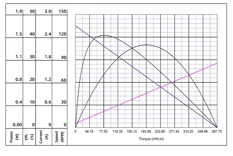
Datasheets often provide performance curves showing how speed, current, power, and efficiency vary with torque.
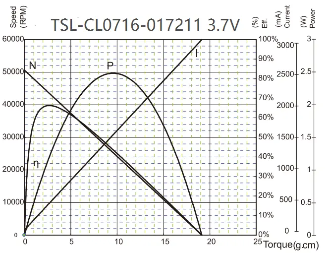
In the figure, the letters N, I, P, and η correspond to the speed-torque curve, current-torque curve, power curve, and efficiency curve respectively.
Speed-Torque curve(N): A line sloping downward. It shows speed falls as torque rises.
Current-Torque curve(I): A line sloping upward. It shows current consumption rises as torque load increases.
Power curve(P): A parabola. Peak around ~50% of stall torque. Represents maximum mechanical power.
Efficiency curve(η): Also a parabola. Its peak often lies at ~10-30% of stall torque. That highest point is the motor’s optimum operating point and sets its rated performance.
These curves reveal an important fact: the motor’s maximum power point is not the best or safest for continuous duty.
At ~50% of stall torque (peak power point) current is high. Heating drives as P_heat = I²R. So at that point, the heating is far higher than at the high-efficiency point (~10-30% stall torque). Excess heat causes insulation aging, magnet demagnetisation, and early failure.
Therefore, performance curves define safe working zones:

- Continuous duty region: Around the highest efficiency point, typically 0–30% of stall torque. The motor can run continuously here without overheating.
- Intermittent duty region: Between highest efficiency and maximum power point, typically 30–60% of stall torque. Motor can run here for short periods but needs cooling time — not for continuous duty.
- Danger zone: Above ~60% of stall torque. Operation here should be strongly avoided as motor may burn out quickly.
Also, datasheet parameters aren’t independent. They are tightly linked by internal physical laws. For example, voltage ∝ no-load speed; current ∝ torque. Knowing these links means motor selection is a system-level task. You can’t pick based on one parameter only.
You must consider load characteristics, power supply capability, driver specs, mechanical design to reach the optimal choice.
How to Choose the Right DC Gear Motor
Turning theory into practice requires a systematic selection method. Motor selection is matching application demands with motor specs, while balancing cost, size and other constraints.
Step One: Determine mechanical requirements (torque & speed)
This is the most important step—it directly decides if the motor can “do the job.”
Calculate required torque: Estimate the torque needed to drive the load. Consider load mass, friction, motion radius, incline etc. For example, for a pulley lifting weight: Torque = Force × Radius.
Determine required speed: Calculate the output speed (RPM) your application needs. For example, if a robot must reach a certain travel speed you compute tube/wheel speed from diameter.
Add safety margin: Add ~20–30% margin on top of the calculated torque. That compensates for friction, efficiency losses and load changes. It ensures the motor has enough head-room for real conditions.
A common mistake is picking the motor based on starting or acceleration peak torque only. That often leads to oversizing—higher cost and lower efficiency in normal use.
The right choice is based on continuous operating torque or RMS torque so the motor won’t overheat during long operation, while ensuring the peak or stall torque can cover startup surges.
Step Two: Determine electrical & control requirements
- Voltage: Choose a motor whose rated voltage matches your power supply. Common: 12 V for battery mobile devices; 24 V for industrial systems.
- Control complexity: Clarify your control needs. If you only need simple start/stop or rough speed control, a brushed motor with simple voltage control may suffice. If you need precise position or speed closed-loop control, consider brushless or encoder-equipped motors.
Step Three: Evaluate physical & environmental constraints
- Size & weight: Measure the space you allocated for the motor. Larger power often means bigger size, but selecting a high power-density solution (like planetary gearbox) gives greater torque in limited space.
- Operating environment: Check temperature, humidity, dust or liquid exposure. For harsh environments you may need motors with certain protection ratings (IP rating) for durability.
- Noise level: For home, office or medical use where noise matters, prioritise low-noise solutions—like brushless motors, planetary or worm gearboxes.
Step Four: Consider duty cycle & lifespan
- Duty cycle (duty ratio): Determine if the motor runs continuously or intermittently. A motor rated for intermittent use might overheat if forced to run continuously.
- Expected lifespan: Match the motor’s expected operational lifespan (which differs greatly between brushed vs brushless motors) with your product’s design life. Avoid the motor becoming the weak link in the system.
Too complicated? No worries! Just tell us your requirements, and we’ll handle the rest. We offer one-stop service to make selection easy and worry-free.
DC Gear Motor Applications
DC gear motors are highly versatile and essential across industries. Using real application cases helps us understand how theory meets practice.
Robotics & Industrial Automation
Robot arms: Their joint motions need very high torque and precise position control to pick heavy items or perform delicate tasks. Planetary-gear DC gear motors are ideal here due to high torque density and low backlash.
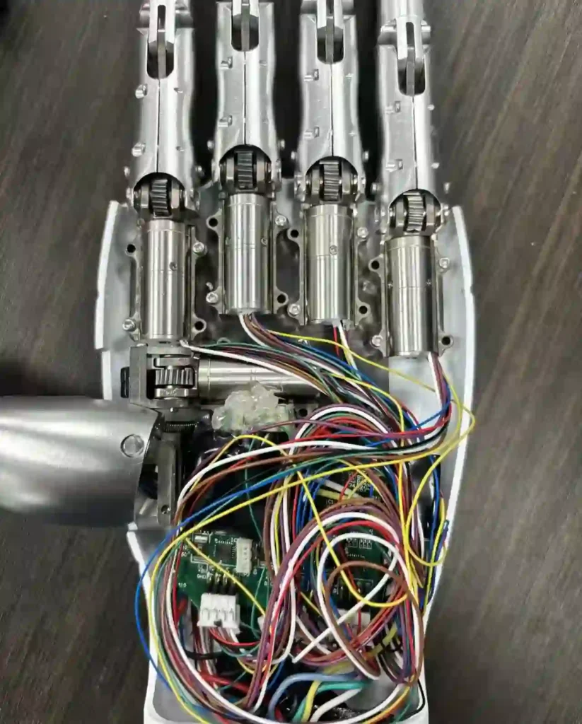
Mobile robots (AGVs): In automated warehouses/factories, autonomous vehicles need strong drive power to move heavy loads smoothly. High-torque DC gear motors provide that power.
Conveyor belts & packaging machines: On assembly lines, DC gear motors drive conveyors at steady, controllable speed and power machinery like labelers, fillers, packers—ensuring process sync and stability.
Automotive systems
Power windows, seats, sunroofs: Compact DC gear motors (often worm-gear type) provide smooth, strong actuation for windows, seat adjustments, roof openings; and their self-locking ability helps hold position when power is off.
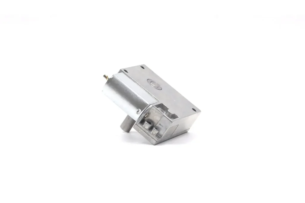
Wipers: Wiper motors must deliver continuous stable torque to overcome blade-glass friction and ensure clear windscreen cleaning in varied conditions.
Electronic Power Steering (EPS): Brushless DC gear motors (BLDC) are increasingly adopted because of high efficiency and reliability. They assist steering and improve driving feel and fuel economy.
Medical & Laboratory Equipment
Infusion pumps & injection pumps: These need extremely precise, slow, stable fluid delivery. DC gear motors give the low-speed, constant-speed control necessary for accurate dosing and safety.
Surgical tools: Micro, high-torque DC gear motors (often hollow-cup type) power drills, saws. Their compact size and ergonomic design give surgeons precise control.
Patient care & mobility devices: Electric wheelchairs, adjustable beds, patient lifts rely on high-torque, low-noise DC gear motors to ensure patient safety and comfort.
Smart Home & Consumer Electronics
Motorised curtains & blinds: Quiet, smooth DC gear motors are key to automatic opening/closing of curtains/blinds. They’re often integrated with smart home systems for remote or voice control.
Smart locks: Small DC gear motors provide enough torque to drive bolts for automatic locking/unlocking of doors.

Robot vacuums: DC gear motors drive the wheels for navigation and movement, and the brush heads for cleaning. They demand high torque, high efficiency (for battery life) and low noise.
High-end appliances: In coffee grinders, vending machines and such, DC gear motors achieve precise, reliable mechanical motion.
Different industries’ needs deeply affect the motor technology and type selected. Medical equipment puts reliability, low noise, precision first ⇒ tends to adopt higher-cost brushless or hollow-cup motors with planetary gearboxes.
The automotive industry needs high reliability and durability but is extremely cost‐sensitive ⇒ mature, cost‐effective brushed motors and worm gear reducers are widely used.
Consumer electronics and smart home fields balance cost, performance, noise ⇒ depending on market positioning they may use low-cost brushed solutions for budget models, or high-end brushless solutions for flagship products.
This shows that the “best” motor solution fully depends on the specific application scenario and its commercial background.
Conclusion: The Future of Motion Control
DC gear motors, as the core component converting electrical energy into precise, powerful mechanical motion, have proven their value across industries.
With compact size, efficient energy conversion and flexible control, they are the indispensable foundation of modern automation.
Looking ahead, many trends point the way: smarter, more integrated, higher-efficiency gear motors.
In short, DC gear motors are not only the backbone of today’s precision motion control—they are the enabling technology for the future of automation, intelligent mobility and the IoT era. With ongoing innovation, they will continue playing a crucial role in driving societal progress.
FAQ
Q1. What is a DC gear motor?
A DC gear motor combines a DC motor with a gearbox to convert high-speed, low-torque rotation into low-speed, high-torque output—ideal for controlled, powerful motion.
Q2. Why use a gear motor instead of a DC motor?
Because the gearbox increases torque and reduces speed, allowing small motors to handle heavier loads and operate with greater precision and stability.
Q3. What are the main types of DC gear motors?
The main types include brushed, brushless, hollow-cup, and stepper gear motors. Each type balances cost, efficiency, precision, and lifespan differently.
Q4. How do I choose the right gear reduction ratio?
Match it to your required speed and torque. A higher ratio gives more torque but slower speed. The right ratio ensures the motor meets your load without overheating or inefficiency.
Q5. What are the key parameters to check on a motor datasheet?
Focus on rated voltage, speed, torque, current, power, and efficiency. These define the motor’s safe operating range and performance.
TSL-Motor: Custom Motor Solutions
Established in 2009, TSL Motor has evolved into a leading innovator in precision drive systems and specialized motor manufacturing. Our 15,000㎡ advanced production facility in Shenzhen houses a skilled workforce of 200+ professionals, delivering an annual output of 2 million units to global markets.
Continuous R&D investment in energy-efficient motor technologies
Lean manufacturing processes ensuring cost-competitive pricing
Agile production capacity scaling for batch customization
Global compliance certifications (CE, RoHS, REACH)
With dual focus on operational excellence and client success, Twin Motor empowers businesses worldwide to achieve technological differentiation. Our engineering team welcomes complex challenges across automotive, robotics, and smart infrastructure applications.
Contact our solutions center to discuss your project requirements or request our technical portfolio.
Tsinglin Motor’s Relevant DC Motor Series
-
 Custom Micro Motors13 products
 - DC Gear Motor173 products
- 6mm Planetary Gear Motor4 products
- 6mm Planetary Metal Gear Motor3 products
- Brushless Gear Motor42 products
- Micro Gear Motor96 products
- Coreless Gear Motor40 products
- N20 Gear Motor26 products
- Plastic Gearbox Motor9 products
- Standard Gear Motor15 products
- Stepper Gear Motor17 products
-
- Planetary Gear Motor59 products
- Spur Gear Motor63 products
- Worm Gear Motor39 products
-
- DC Motor84 products
- Brushed DC Motor17 products
- Brushless DC Motor37 products
- Inrunner Rotor BLDC Motor8 products
- Outrunner Rotor BLDC Motor26 products
-
- Coreless DC Motor17 products
- Micro DC Motor16 products
-
- Dexterous Hand Drive Module28 products
- Micro Linear Actuators13 products
- Stepper Motor32 products
- Micro Stepper Motor13 products
- NEMA Stepper Motor9 products
- Stepper Motor Linear Actuator11 products
-
- Vibration Motors76 products
- Brushless Vibration Motor8 products
- Coin Vibration Motor24 products
- Coreless Vibration Motor3 products
- Encapsulated Vibration Motor6 products
- Linear Resonant Actuator17 products
- Powerful Vibrating Motor17 products
- SMD Vibration Motor4 products
- Sonic Vibration Motor2 products
-