Published: NOVEMBER 30, 2025
Updated:SEPTEMBER 10, 2026
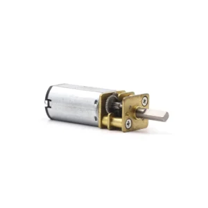
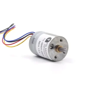
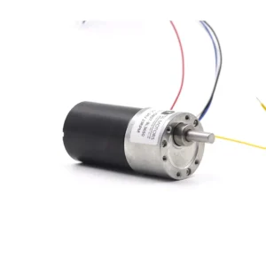
A high-torque DC motor is not a separate motor technology. It is a DC motor system designed to deliver the torque required by a load at a defined speed, duty cycle and temperature. The final result may use a brushed or brushless motor, with or without a gearbox.
Voltage alone does not determine torque. Motor torque is primarily related to torque constant and current, while the available speed depends on applied voltage, back EMF and load. A gearbox can multiply output torque, but it also reduces speed, introduces efficiency losses and imposes its own continuous and intermittent torque limits.
A reliable selection process therefore begins with the required load torque, loaded speed, acceleration, duty cycle and mechanical envelope. Only after these values are defined should the engineer choose between 12V and 24V, brushed and brushless commutation, and spur, planetary or worm gearing.
This guide explains that process and identifies the limits that must be checked before a motor is approved for continuous operation.cons of BLDC.
Key Takeaways
- Begin with the required output torque, loaded speed, acceleration, duty cycle and operating temperature—not with motor voltage or gearbox type.
- Motor torque is approximately proportional to torque constant and current. Voltage mainly affects the speed that can be reached against back EMF and electrical losses.
- For the same system power, a 24V supply generally carries less current than a 12V supply, reducing losses in cables, connectors and controllers. It does not automatically make the motor more efficient or produce more torque.
- Brushed and brushless motors can both provide high starting torque when properly sized. The practical differences are commutation, controller requirements, service life, noise, cost and thermal performance.
- A gearbox increases output torque while reducing speed, but usable continuous torque is limited by efficiency, motor temperature and the gearbox’s mechanical rating.
- Final approval should be based on testing at the actual operating point, including terminal voltage, RMS current, winding or housing temperature, startup current, transient load and gearbox temperature.
Define the Required Operating Point Before Choosing a Motor
“High torque” is not a standardized motor category. The torque required for a valve, robot joint, lifting mechanism or drive wheel can differ substantially. Selecting a motor simply because it is described as “high torque” does not confirm that it can operate at the required speed and duty cycle without overheating.
Motor selection should therefore begin with the load-side operating point.
Calculate the Output Load Torque
When a force acts at a known radius:
Load torque = Force × Radius
Tload = F × r
For a vertical lifting mechanism:
Tload = Mass × Gravitational acceleration × Radius
The result represents the static torque at the output. Depending on the mechanism, the calculation may also need to include friction, seal resistance, spring preload, gravity direction and external disturbance.
When specifications use different units, such as N·m, mN·m, kgf·cm or oz·in, use the TSL Motor Torque Unit Converter before comparing values.
Separate Continuous, Acceleration and Peak Torque
Continuous torque is the torque required during sustained operation. It must remain within the thermal limits of both the motor and gearbox.
Acceleration torque is required to change the speed of the motor, transmission and load:
Acceleration torque = Total reflected inertia × Angular acceleration
Tacc = J × alpha
An initial peak-torque estimate can be expressed as:
Tpeak = Static load torque + Friction torque + Acceleration torque
Additional allowance may be required for impact, uncertain friction, load variation or temporary obstruction. There is no universal safety factor suitable for every application. The required margin depends on the load profile, reversal frequency, operating temperature, expected life and consequences of a stall.
Define Loaded Speed and Duty Cycle
The required speed should always be defined under load. A no-load speed value does not show whether the motor can maintain the target speed while producing the required torque.
For a preliminary gearbox calculation:
Motor speed ≈ Required output speed × Gear ratio
Required motor torque ≈ Required output torque ÷ (Gear ratio × Gearbox efficiency)
The first equation estimates motor speed before accounting for gearbox speed loss. The second estimates the motor-side torque required to produce the target output torque.
The fundamental DC motor relationships are:
Motor torque ≈ Torque constant × Current
Back EMF ≈ Back-EMF constant × Motor speed
MIT OpenCourseWare derives these relationships and explains why current is used to control torque while voltage and back EMF influence motor speed in its Electric Motors lecture notes.
For a changing load cycle, RMS torque can provide an initial estimate of thermal demand:
TRMS = sqrt[(T1² × t1 + T2² × t2 + …) ÷ (t1 + t2 + …)]
RMS torque is not a complete selection result. It does not independently account for poor cooling at low speed, repeated direction changes, shock loading, gearbox peak-torque limits or long acceleration periods.
Before comparing motors, record:
- Continuous and peak output torque;
- Loaded output speed;
- Acceleration and deceleration time;
- On-time, off-time and complete cycle duration;
- Starts and reversals per hour;
- Ambient temperature and available cooling;
- Radial and axial shaft loads;
- Expected operating life.
These requirements establish the operating point used to compare voltage, winding, motor type and gearbox options. Final approval should be based on testing the complete drive system under representative load and temperature conditions.
12V vs. 24V High-Torque DC Motors
Choosing between 12V and 24V is primarily a system-level decision. Voltage influences supply current, cable size, controller requirements and the speed range available from a particular winding. It does not independently determine motor torque.
Why Does a 24V System Draw Less Supply Current?
Electrical input power can be expressed as:
Electrical input power = Voltage × Supply current
Pin = V × I
For an electrical input of 120 W:
- A 12V system draws approximately 10 A;
- A 24V system draws approximately 5 A.
Real current will vary with controller efficiency, motor efficiency and operating point, but the relationship illustrates why higher-voltage systems are often used when power must be transmitted through cables and connectors.
Cable loss can be estimated as:
Cable loss = Current² × Cable resistance
Ploss = I² × R
If voltage is doubled and supply current is halved while cable resistance remains unchanged, the calculated cable loss falls to approximately one quarter. Lower supply current can also reduce connector heating, voltage drop and the required conductor cross-section.
This does not mean that the motor’s internal copper loss automatically falls to one quarter. A 24V winding normally uses a different number of turns, wire diameter, resistance and motor constant from a 12V winding. Motor temperature must therefore be evaluated from the actual winding data and operating current.
Does 24V Produce More Torque?
Not by itself. Motor torque is approximately:
Motor torque = Torque constant × Winding current
T = Kt × I
A properly designed 12V motor and 24V motor can produce similar torque within the same mechanical envelope. Their winding resistance, speed constant and required current will be different.
Applying 24V directly to a winding designed only for 12V can cause excessive current at startup, excessive no-load speed, brush arcing, controller overload or winding overheating. PWM duty-cycle reduction does not remove the need to check peak current, current ripple and maximum permitted motor speed.
Voltage and winding selection must therefore be treated together.
When Is 12V the Better Choice?
A 12V platform is often appropriate when:
- The machine already uses a regulated 12V supply;
- The motor must operate directly from a 12V battery or vehicle electrical system;
- Cable runs are short and the required power is moderate;
- Suitable 12V drivers, relays and protection devices are already available;
- Compatibility with existing equipment is more important than reducing supply current.
A 12V motor is not limited to low-torque applications. It can produce substantial torque when the winding, driver, wiring and thermal design support the required current.
When Is 24V the Better Choice?
A 24V platform is often appropriate when:
- The machine already uses a 24V industrial power bus;
- Higher power must be transmitted through limited cable space;
- Long cable runs make voltage drop important;
- Connector or controller current is a design constraint;
- The application requires repeated acceleration or long operating periods;
- Several actuators share the same industrial power supply.
The main advantage is lower supply-side current for the same electrical power. Continuous torque still depends on the motor winding, allowable current, cooling and gearbox rating.
Practical 12V vs. 24V Comparison
| Design Factor | 12V System | 24V System |
|---|---|---|
| Supply current at the same input power | Higher | Lower |
| Cable and connector requirements | Usually heavier at higher power | Easier to manage at higher power |
| Compatibility | Common in vehicles and portable equipment | Common in automation and industrial equipment |
| Motor torque | Depends on Kt and winding current | Depends on Kt and winding current |
| Motor temperature | Depends on winding loss and cooling | Depends on winding loss and cooling |
| Controller requirement | Must support 12V and peak current | Must support 24V, transients and peak current |
| Best selection basis | Existing power architecture and operating point | Existing power architecture and operating point |
Engineering Selection Rule
Choose the system voltage from the available power source, total electrical power, allowable supply current, cable length and controller limits. Then select a motor winding whose loaded speed and continuous torque fall within the permitted thermal operating range.
Measure voltage at the motor or controller terminals during startup and full load. A nominal 24V supply that falls substantially under load may perform worse than a stable 12V supply designed for the required current.
The U.S. Department of Energy’s Motor Systems resources similarly treats the motor, drive, power supply and driven load as one system rather than evaluating motor efficiency in isolation.
For available voltage platforms, winding options and motor constructions, see the TSL Motor DC motor range.
BDC vs. BLDC: Which is Better for High Torque Projects?
Brushed DC and brushless DC motors can both produce high starting and continuous torque when their winding, magnetic circuit, driver and cooling system are correctly sized. Neither technology is automatically the higher-torque option.
For both motor types, electromagnetic torque can be approximated as:
Motor torque = Torque constant × Motor current
T = Kt × I
The practical difference is how current is commutated, controlled and thermally managed.
High Torque Brushed DC Motor

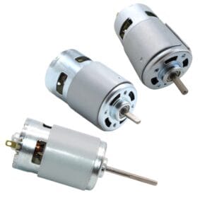
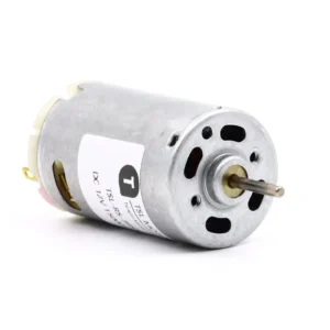
A brushed DC motor uses brushes and a commutator to switch current through the rotating armature windings. It can operate from a DC supply with relatively simple electronics, although bidirectional motion, PWM speed control and current limiting normally require an H-bridge driver.
A brushed motor can provide high starting torque if the power supply, winding and driver can safely provide the required startup current. Its advantages include:
- Simple speed and direction control;
- Lower controller complexity;
- Lower initial system cost in many applications;
- Practical operation for intermittent or moderate-duty mechanisms;
- Easy integration when precise electronic commutation is unnecessary.
Its main limitation is the mechanical commutation system. Brush and commutator wear depends on current, speed, temperature, PWM current ripple, vibration and reversal frequency. Frequent starts, stops and reversals can therefore shorten service life even when the average operating time is relatively low.
Brush arcing can also create electrical noise. Suppression components, grounding, cable routing and controller design may be required when the motor operates near sensitive sensors or communication circuits.
High Torque Brushless DC Motor
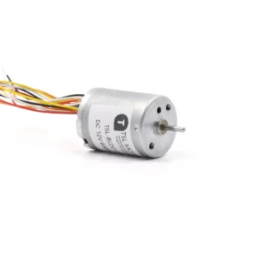
A BLDC motor replaces brushes and the mechanical commutator with an electronic controller. The driver switches current through the stator windings according to rotor position.

Because there is no brush contact, BLDC motors are generally better suited to applications requiring long service life, frequent cycling, high rotational speed or reduced maintenance. In many designs, the stator windings also provide a more direct path for transferring heat to the housing.
However, a BLDC motor cannot operate correctly without a compatible driver. Peak and continuous torque depend on phase current, commutation method, current sensing, controller limits and motor temperature.
Low-speed starting also requires attention:
- Hall sensors provide rotor-position information for controlled startup;
- Encoders support more precise position and low-speed control;
- Sensorless control based on back EMF may be less reliable at zero or very low speed;
- Field-oriented control can improve torque smoothness but increases control and tuning requirements.
BLDC operation also produces switching-related electromagnetic interference, so removing brushes does not automatically make the complete system electrically silent.
Brushed DC vs. BLDC Comparison
| Design Factor | Brushed DC Motor | BLDC Motor |
|---|---|---|
| Torque capability | Determined by Kt, current and thermal limits | Determined by Kt, phase current, controller and thermal limits |
| Starting torque | High when startup current is available | High when the driver provides controlled phase current |
| Commutation | Mechanical brushes and commutator | Electronic controller |
| Basic control | Relatively simple | Requires a compatible BLDC driver |
| Low-speed startup | Direct and predictable with sufficient current | Depends on Hall, encoder or sensorless strategy |
| Service life | Often limited by brush and commutator wear | No brush wear; bearings and electronics remain life-limiting components |
| Electrical noise | Brush arcing and PWM can generate EMI | PWM switching can generate EMI |
| Frequent reversing | Increases brush and commutator stress | Usually better suited when control and thermal design are correct |
| Initial cost | Often lower | Motor and controller cost are usually higher |
| Maintenance | Brush inspection or replacement may be required | Usually lower mechanical maintenance |
Practical Selection Rule
Choose a brushed DC motor when the application prioritizes simple control, lower initial cost, intermittent duty and straightforward replacement.
Choose a BLDC motor when the application prioritizes long operating life, frequent cycling, high speed, closed-loop control or reduced maintenance.
Do not choose between them using starting torque alone. Compare both candidates at the required loaded speed and continuous torque, then verify startup current, RMS current, temperature rise, driver capacity and expected operating life.
For a more detailed comparison of commutation, control, efficiency and service life, see Brushless DC vs. Brushed Motor: Making the Right Choice.
Which Gearbox Structure is Best for High Torque DC Motors?
A gearbox should not be selected from gear ratio or theoretical torque multiplication alone. The correct choice also depends on the required output speed, continuous and peak torque, available installation space, duty cycle, backlash, efficiency, backdrivability and output-shaft load.
The basic relationships are:
Output speed ≈ Motor speed ÷ Gear ratio
Calculated output torque ≈ Motor torque × Gear ratio × Gearbox efficiency
However, calculated output torque is not automatically usable output torque. The gearbox has its own continuous and intermittent torque limits:
Allowable continuous output torque = the lower of calculated output torque and gearbox rated continuous torque
Peak torque must also remain within the gearbox’s intermittent rating and permitted duration. Increasing the ratio cannot compensate for an undersized gearbox, weak output bearings or an overheating motor.
Spur Gearbox
A spur gearbox uses external gears mounted on parallel shafts. Depending on the gear arrangement, the input and output shafts may be coaxial or offset.
Spur gearboxes are often efficient, mechanically straightforward and cost-effective. Their actual torque capacity depends on gear module, tooth width, material, heat treatment, shaft support and bearing design—not simply on the fact that spur gears are used.
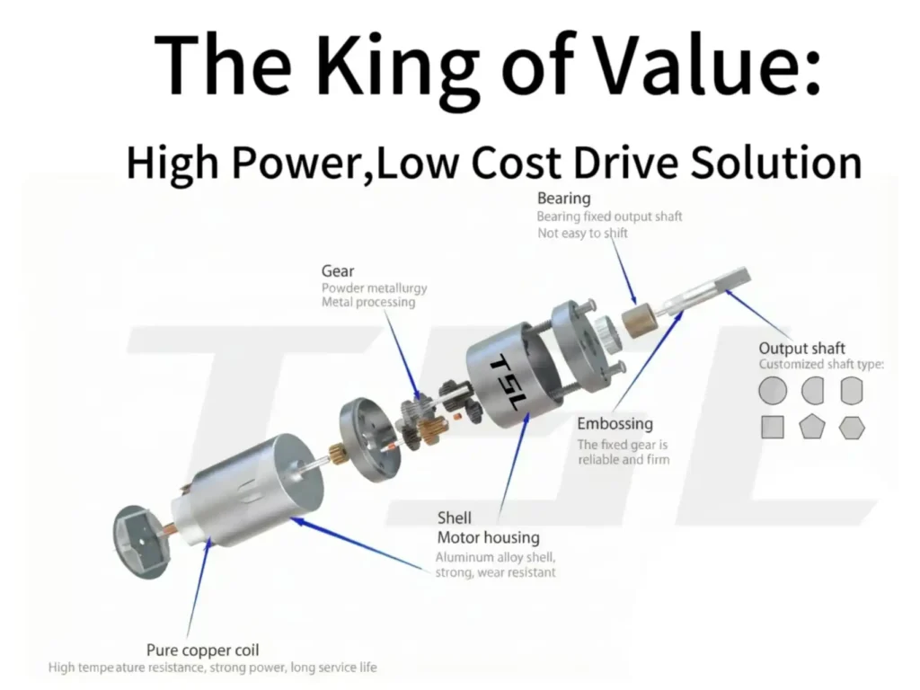
They are a practical starting point when the application requires moderate reduction ratios, good efficiency and controlled cost. Adding more stages provides a higher ratio but also increases gearbox length, accumulated backlash and mechanical losses.
For a more detailed explanation of layouts and design limits, see Spur Gear Motor: Structure, Pros & Cons, and Selection.
Planetary Gearbox
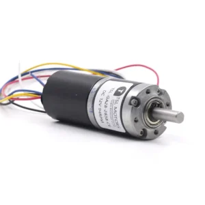
A planetary gearbox arranges planet gears around a central sun gear inside a ring gear. Its coaxial layout and multiple gear contacts can provide high torque capacity within a compact diameter.
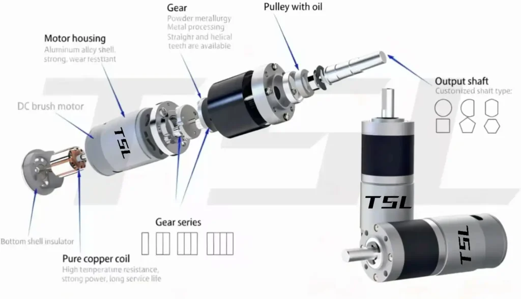
The load is distributed among several planet gears, but the sharing is not perfectly equal in a real gearbox. Manufacturing tolerances, carrier stiffness, gear alignment and bearing support affect how the load is divided.
A planetary gearbox is therefore well suited to applications requiring compact size, coaxial input and output, or high torque density. It is not automatically low-backlash or more efficient than every spur gearbox. Backlash, efficiency and life must be checked for the actual number of stages and operating load.
See Planetary Gear Motors: Design, Advantages, Types, and Selection for a deeper explanation of planetary construction and operating limits.
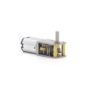
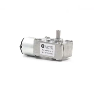
Worm Gearbox
A worm gearbox normally provides a right-angle transmission and can achieve a relatively high reduction ratio in a compact arrangement. It may also provide resistance to backdriving, which can be useful in adjustment mechanisms, valves and lifting systems.
Its efficiency and temperature rise depend strongly on the lead angle, ratio, materials, lubrication, speed and load. Because sliding contact occurs between the worm and worm wheel, heat generation can become an important continuous-duty limit.
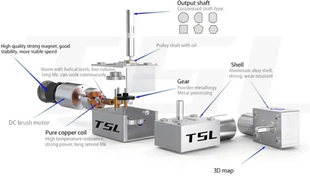
A worm gearbox must not be assumed to be self-locking. Some designs can be backdriven, particularly under vibration, wear or changing lubrication conditions. A safety-critical load should use a properly rated brake or locking device rather than relying only on the worm drive.
For the conditions that influence backdriving, see DC Worm Gear Motor: Principles, Self-Locking & Selection.
Gearbox Comparison
| Gearbox | Typical layout | Main advantage | Important limitation | Suitable starting point |
|---|---|---|---|---|
| Spur | Parallel shafts; coaxial or offset designs are possible | Simple, efficient and cost-effective | Higher ratios require additional stages | Moderate ratios and cost-sensitive mechanisms |
| Planetary | Coaxial input and output | Compact torque density and multiple gear contacts | More complex; performance depends on load sharing and tolerances | Compact actuators, robotics and high-torque-density systems |
| Worm | Usually right-angle | High ratio in a compact layout and possible backdriving resistance | Sliding loss, heat and limited efficiency | Right-angle drives, adjustment mechanisms and low-speed outputs |
Practical Selection Rule
Choose a spur gearbox when efficiency, simplicity and cost are the priorities. Begin with a planetary gearbox when the installation requires a compact coaxial drive and higher torque density. Consider a worm gearbox when a right-angle layout, a high single-stage ratio or resistance to backdriving is important.
For every structure, verify:
- Rated continuous and intermittent output torque;
- Efficiency at the actual speed and load;
- Permitted duty cycle and gearbox temperature;
- Backlash and positioning requirements;
- Radial and axial output-shaft loads;
- Backdriving or holding requirements;
- Expected operating life and lubrication conditions.
The best gearbox is not the one with the highest theoretical torque multiplication. It is the structure that can deliver the required output torque and speed continuously without exceeding its thermal, mechanical or positioning limits.
How TSL Motor Develops a High-Torque DC Motor Solution
A high-torque motor solution cannot be defined by voltage, motor diameter or stall torque alone. TSL Motor begins with the required output operating point and then matches the motor winding, commutation method, gearbox and feedback system.
Information Required for Selection
Before comparing motor models, define the following conditions:
- Required continuous output torque and speed;
- Peak torque, duration and repetition frequency;
- Available voltage and maximum supply current;
- Operating time, duty cycle and reversal frequency;
- Maximum motor and gearbox dimensions;
- Ambient temperature and permitted surface temperature;
- Radial and axial loads on the output shaft;
- Required service life, noise and positioning accuracy;
- Controller, Hall sensor or encoder interface.
These conditions help distinguish a continuous thermal requirement from a short acceleration or startup event. A motor that can briefly produce the requested torque may still overheat if that value is required continuously.
Motor and Gearbox Matching
TSL Motor can evaluate brushed, brushless and coreless motor structures according to the control requirements, available space and expected service life. The winding can then be matched to the selected supply voltage and target loaded speed.
If a gearbox is required, its ratio is selected from the motor speed and target output speed. The calculated output torque is subsequently checked against gearbox efficiency, continuous torque rating, intermittent torque limit, bearing load and expected life.
The process can be summarized as follows:
| Application input | Main design decision |
|---|---|
| Continuous torque and loaded speed | Motor size, winding and gear ratio |
| Peak torque and acceleration time | Current limit and intermittent gearbox capacity |
| 12V or 24V power system | Winding resistance, speed constant and driver rating |
| Continuous or intermittent duty | Motor temperature rise and gearbox thermal limit |
| Frequent starting or reversing | Driver control, current limiting and mechanical wear |
| Positioning requirement | Encoder location, resolution, backlash and control method |
| Radial or axial shaft load | Output bearing and shaft structure |
Available Customization
Depending on the project, the configurable items may include:
- Rated voltage and winding parameters;
- Brushed, brushless or coreless motor construction;
- Spur, planetary or worm gearbox;
- Gear ratio and target output speed;
- Output shaft length, diameter and profile;
- Hall sensors or magnetic and optical encoders;
- Lead wires, connectors and cable length;
- Bearings, lubrication and gearbox materials;
- Driver and communication options.
Not every parameter can be optimized independently. For example, increasing the gear ratio reduces output speed and may add stages, losses and backlash. Increasing current can raise torque, but it also increases winding temperature and driver requirements. Final specifications therefore need to be evaluated as a complete operating system.
Engineers can first compare the available DC gear motor range and then submit the actual operating conditions through the customized motor solutions page. Model recommendations should be confirmed with performance data or sample testing at the required load rather than selected from no-load speed or stall torque alone.
High-Torque DC Motor Selection Summary
A high-torque DC motor should be selected from the required operating point, not from voltage, motor type or stall torque alone. Use the following sequence:
- Define the required continuous torque, peak torque, loaded speed and duty cycle.
- Select 12V or 24V according to the available power system, current limit, wiring and controller—not because one voltage inherently produces more torque.
- Choose brushed or brushless construction according to control complexity, service life, operating cycles, electrical noise and cost.
- Select the gearbox from the required ratio, output torque, layout, efficiency, backlash and backdriving requirements.
- Verify the complete system through loaded current, terminal voltage, motor temperature, gearbox temperature and sample testing.
The final operating point must remain within both the motor’s thermal limits and the gearbox’s mechanical ratings. A motor that produces sufficient startup torque may still be unsuitable for continuous operation, while a gearbox with a high ratio may still be limited by efficiency, temperature, backlash or output-shaft load.
The correct solution is therefore the motor, winding, driver and gearbox combination that delivers the required motion reliably under the actual load and operating cycle.
FAQ
Q1: Why are high torque dc motors critical?
A: They can drive heavy loads, increase system efficiency and stability, and allow for a more compact system design.
Q2: Which is better: 12V or 24V?
A: 24V is generally better. It has lower current, less heat, more stable torque, and longer life, suitable for industrial continuous operation.
Q3: How do I choose between DC (Brushed) and BLDC (Brushless)?
A: DC is suited for: strong starting impact force and low cost.
BLDC is suited for: long life, high efficiency, and quiet operation.
Q4:Which gearbox structure is best for high torque?
A: The Planetary Gearbox. it provides the highest torque density in a limited space.
TSL MOTOR Products
-
 Custom Micro Motors13 products
 - DC Gear Motor173 products
- 6mm Planetary Gear Motor4 products
- 6mm Planetary Metal Gear Motor3 products
- Brushless Gear Motor42 products
- Micro Gear Motor96 products
- Coreless Gear Motor40 products
- N20 Gear Motor26 products
- Plastic Gearbox Motor9 products
- Standard Gear Motor15 products
- Stepper Gear Motor17 products
-
- Planetary Gear Motor59 products
- Spur Gear Motor63 products
- Worm Gear Motor39 products
-
- DC Motor84 products
- Brushed DC Motor17 products
- Brushless DC Motor37 products
- Inrunner Rotor BLDC Motor8 products
- Outrunner Rotor BLDC Motor26 products
-
- Coreless DC Motor17 products
- Micro DC Motor16 products
-
- Dexterous Hand Drive Module28 products
- Micro Linear Actuators13 products
- Stepper Motor32 products
- Micro Stepper Motor13 products
- NEMA Stepper Motor9 products
- Stepper Motor Linear Actuator11 products
-
- Vibration Motors76 products
- Brushless Vibration Motor8 products
- Coin Vibration Motor24 products
- Coreless Vibration Motor3 products
- Encapsulated Vibration Motor6 products
- Linear Resonant Actuator17 products
- Powerful Vibrating Motor17 products
- SMD Vibration Motor4 products
- Sonic Vibration Motor2 products
-