Published: NOVEMBER 15, 2025
Updated: August 31, 2026
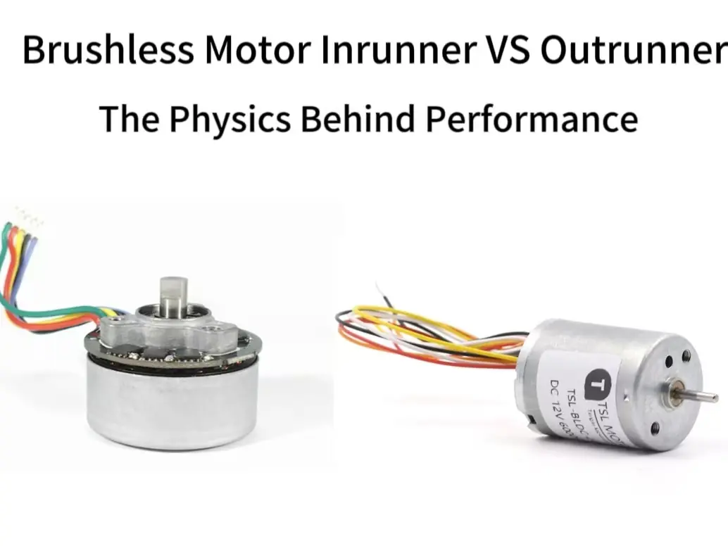
If speed is the priority, start with an inrunner. If you need more torque from a compact diameter and want to drive the load directly, an outrunner is usually the better starting point.
That is the short answer—but it is not the whole answer.
Inrunner BLDC motors place the rotor inside the stator. Their lighter, smaller-radius rotor responds quickly, is easier to manage at high speed and leaves the outer housing stationary for mounting and heat transfer.
Outrunner BLDC motors rotate an external rotor bell around the stator. The larger working radius gives designers more leverage for producing torque, which is why outrunners are widely used in propellers, gimbals and other direct-drive systems.
In real projects, however, the motor with the higher advertised torque or speed is not automatically the better choice. Load inertia, continuous operating temperature, mounting space, cooling, rotor balance and transmission design often decide the result.
This guide explains where each motor topology performs best and provides practical selection rules based on torque, speed, inertia, thermal management and mechanical integration.
Wichtigste Erkenntnisse
- Choose an inrunner first when high speed, fast acceleration, a stationary outer housing or straightforward conductive cooling is the priority.
- Choose an outrunner first when direct drive, compact axial length and higher torque from a relatively large rotor radius are more important.
- A larger rotor radius can improve torque-producing leverage, but total torque still depends on motor length, magnetic loading, winding design, current and temperature limits.
- Motor Kv describes speed per volt under defined conditions. It does not, by itself, tell you how much continuous torque the motor can deliver.
- Inrunners usually have lower rotor inertia and respond faster to speed changes. Outrunners carry more rotating mass farther from the shaft, which can improve smoothness but requires greater attention to balance.
- Continuous torque is ultimately limited by temperature. Compare the complete thermal path—from the windings to the housing, mounting structure and surrounding air—not just the rotor arrangement.
- There is no universal winner. Select the topology from the required operating point, load inertia, duty cycle, cooling method, mounting space and environmental conditions.
How Do Inrunner and Outrunner Motors Differ?
Both designs use electronic commutation to create a rotating magnetic field, but the rotor is positioned differently.
Inrunner Motor
In an inrunner, the rotor turns inside the stator while the outer housing remains stationary. Concentrating the rotating mass closer to the shaft usually gives the motor lower rotor inertia, supporting rapid acceleration and high-speed operation. The stationary housing also provides a practical mounting and heat-transfer surface.
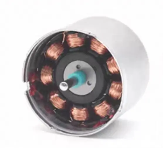
For a more detailed discussion of its construction, limitations and design considerations, see our guide to inrunner motor advantages, disadvantages and engineering considerations.
Outrunner Motor
In an outrunner, an external rotor bell rotates around the stator. Its larger air-gap radius provides a longer moment arm for producing torque, making the topology useful for compact direct-drive systems.
Because more rotating mass is positioned farther from the shaft, an outrunner generally has higher rotor inertia. Rotor stiffness, magnet retention and dynamic balance become more important as operating speed increases.
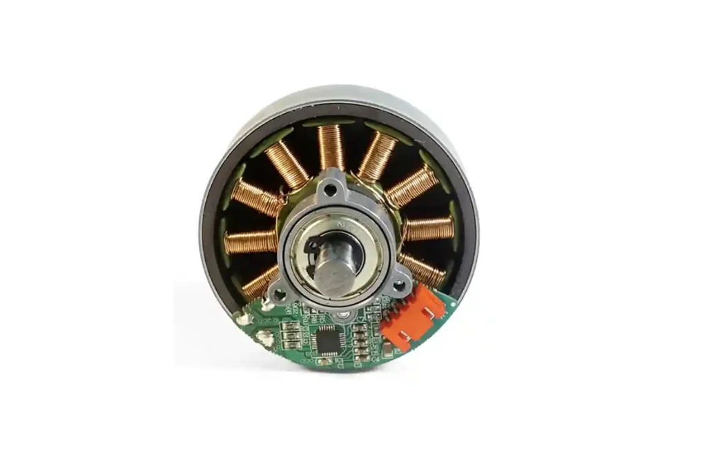
For more detail on thermal management, balance, mounting and common failure risks, read outrunner motor advantages, disadvantages and key engineering challenges.
Why Rotor Position Matters
Rotor position affects torque-producing radius, rotor inertia, cooling, mounting and high-speed mechanical behavior. These differences provide a useful first selection filter, but the final decision must still be based on the required operating point, winding, current limit, thermal design and driven load.
Inrunner vs Outrunner Torque, Speed, and Kv
Torque and speed are the most common reasons for comparing inrunner and outrunner motors, but neither value is determined by rotor position alone.
Which Motor Produces More Torque?
The basic relationship is straightforward:
Torque = Tangential Force × Radius
T = Ft × r

If two motors produce the same tangential electromagnetic force, the motor with the larger effective air-gap radius produces more torque. In an outrunner, the air gap is positioned closer to the motor’s outer diameter, giving the electromagnetic force a longer moment arm. This is the main reason outrunners generally have an advantage in direct-drive torque.
The radius can provide an additional benefit. If electromagnetic shear stress and active length are similar, increasing the air-gap radius also increases the active cylindrical surface area. Torque can therefore increase approximately with the square of the air-gap radius:
T ≈ 2π × σ × L × r²
Where σ is the average tangential electromagnetic shear stress, L is the active motor length and r is the air-gap radius.
This does not mean that outer diameter alone determines the final torque of a finished motor. Magnetic loading, winding design, current, active length, air-gap quality and temperature limits still affect the available electromagnetic force.
From the electrical side, motor torque can also be expressed as:
T = Kt × I
This equation shows how winding design and current convert the geometric torque advantage into actual motor output. In practice, an outrunner gains leverage from its larger radius, but the winding and thermal design determine how much of that advantage can be used continuously.
Which Motor Is Better for High Speed?
An inrunner is usually the better starting point when high rotational speed is the priority. Its smaller rotor diameter results in lower surface speed at the same rpm and makes rotor strength, magnet retention and dynamic balance easier to manage. Its stationary outer housing also provides a convenient mounting and heat-transfer surface.
An outrunner can still operate at high speed, but the larger rotating diameter places greater mechanical demands on the rotor bell, magnets, bearings and balance quality. A small amount of imbalance becomes more significant as rotational speed increases.
High-speed operation also increases iron loss, bearing loss and other speed-dependent losses. The safe speed limit must therefore come from verified manufacturer data and testing, not from Kv or motor topology alone.
What Does Motor Kv Actually Tell You?
Motor Kv describes the approximate ideal no-load speed produced per volt:
Ideal no-load speed ≈ Kv × Applied Voltage
For example, a 1,000 Kv motor supplied with 24 V has an idealized no-load speed of approximately 24,000 rpm.
The measured speed will normally be lower because some of the applied voltage is lost through winding resistance and the controller. Bearing friction, iron loss, air resistance and the external load reduce the speed further.
Kv is not a direct measure of motor quality or total torque capability. Under consistent units and measurement conventions, a lower Kv corresponds to a higher torque constant. However, continuous torque still depends on the permitted winding current and temperature rise.
When comparing two datasheets, confirm that Kv is measured using the same phase, line-voltage and commutation conventions. Otherwise, the published values may not be directly comparable.
Practical Selection Rule
Start with the required loaded speed and continuous torque—not Kv alone.
Choose an inrunner as the first option when the application requires high speed, rapid acceleration or frequent speed changes. Choose an outrunner as the first option when the load benefits from direct-drive torque at a lower speed and can accept greater rotor inertia.
Then verify the motor’s winding, continuous current, temperature rise, controller capability, mounting method and mechanical speed limit at the actual operating point. For a broader explanation of these parameters, see our guide to how a brushless DC motor works and what determines its performance.
Rotor Inertia, Acceleration, and Outrunner Balance
Torque tells us how strongly a motor can turn the load. Rotor inertia tells us how quickly the motor itself can change speed. This distinction is important in applications that start, stop or reverse frequently.
How Does Rotor Inertia Affect Response?
Rotational inertia depends strongly on how far the rotating mass is located from the shaft. A simplified relationship is:
J ∝ m × r²
Where:
- J is the moment of inertia;
- m is the rotating mass;
- r is the distance of that mass from the rotational axis.
An inrunner concentrates its rotor mass closer to the shaft, so it generally has lower rotor inertia. Less torque is required to accelerate or decelerate the rotor, which is useful in high-speed positioning systems, pumps, spindles and applications with frequent speed changes.
An outrunner places the rotor bell and magnets farther from the shaft. This normally increases rotor inertia. The motor may resist sudden speed changes more strongly, but it can also maintain smoother rotation when the load does not require rapid acceleration or reversal.
The actual acceleration is determined by the available accelerating torque and the total inertia:
α = Tacc ÷ Jtotal
The total inertia must include the motor rotor, coupling, pulley, propeller, gearbox components and driven load. In many systems, load inertia matters more than the difference between the two motor topologies.
Why Does Outrunner Balance Matter More at High Speed?
Any offset between the rotor’s center of mass and its axis of rotation creates an unbalance force. That force increases rapidly with rotational speed:
Funbalance = m × e × ω²
Where:
- m is the unbalanced mass;
- e is its distance from the rotational axis;
- ω is rotational speed.
Because the force increases with the square of speed, an outrunner that feels acceptable at low rpm may produce noticeable vibration, noise and bearing load at its actual operating speed.
The larger rotating diameter also makes manufacturing errors more influential. Uneven magnet mass, adhesive distribution, rotor-bell runout, shaft misalignment and attached components can all change the final balance condition.
How Should an Outrunner Motor Be Balanced?
A production-quality outrunner should be balanced as a complete rotating assembly rather than by checking the rotor bell alone.
A practical balancing process is:
- Inspect the assembly first. Check shaft runout, bearing condition, rotor-bell deformation, magnet position and adhesive distribution. Balancing should not be used to hide a damaged or incorrectly assembled rotor.
- Measure vibration amplitude and phase. Use suitable balancing equipment to identify the amount and angular position of the residual unbalance.
- Apply a controlled correction. Add correction mass at the indicated position or remove a small, controlled amount of material from an approved correction area.
- Retest across the operating range. Confirm that residual vibration remains within the specified limit and that no critical vibration appears near the intended working speed.
Static balancing may be sufficient for a short, disc-like rotor, while a longer rotor assembly may require two-plane dynamic balancing. The required correction planes and permitted residual unbalance should be defined from the motor’s geometry, operating speed and application requirements.
ISO 21940-11 specifies balancing procedures, residual-unbalance tolerances and the number of correction planes for rotors with rigid behavior.
Randomly attaching tape or adhesive and running the motor at maximum speed is not a controlled balancing method. High-speed verification should use a guard, secure fixture and appropriate vibration measurement equipment.
Practical Selection Rule
Choose an inrunner when the system must accelerate, decelerate or reverse quickly and rotor inertia needs to remain low.
Choose an outrunner when direct-drive torque and smooth steady rotation are more valuable than the fastest possible transient response. If the outrunner will operate at high speed, include rotor balance, magnet retention and bearing load in the design review rather than treating them as final inspection items.
Thermal Management and Environmental Protection
Continuous torque is ultimately a thermal question. A motor may produce high peak torque for a short time, but it can only maintain that torque if the generated heat leaves the windings fast enough.
Where Does the Heat Come From?
At low and moderate speeds, winding copper loss is usually one of the main heat sources:
Copper Loss = Irms² × R
As speed increases, iron loss, bearing friction, windage and controller-related current ripple can become more important. A simplified thermal relationship is:
Temperature Rise ≈ Total Power Loss × Thermal Resistance
This means that two motors producing similar torque can reach very different winding temperatures if their cooling paths, mounting conditions or ambient temperatures are different.
How Does an Inrunner Remove Heat?
In an inrunner, the stator is connected to a stationary outer housing. This usually provides a short and practical conduction path from the windings and stator laminations to the housing, mounting flange or machine frame.
For this reason, an inrunner is often easier to integrate with a metal chassis, heat sink, water jacket or other conductive cooling structure. The stationary housing also simplifies the use of seals.
However, an inrunner is not automatically waterproof or suitable for a sealed environment. Its IP rating depends on the complete motor construction, including the shaft seal, bearings, cable outlet, connectors and housing joints.
How Does an Outrunner Remove Heat?
An outrunner also has stationary windings, so heat can be conducted through the stator carrier, mounting base or central support. It does not rely on air convection alone.
The rotating bell can create airflow around the motor and improve external convection in open installations. This is useful in drones, fans and other applications with sufficient surrounding air movement.
The challenge appears when the motor is enclosed. Restricting airflow can reduce cooling, while the enclosure must still maintain safe clearance around the rotating bell. A sealed outrunner system is possible, but the enclosure, bearing arrangement and thermal path must be designed together.
Compare Ratings Under the Same Conditions
Do not compare continuous torque figures without checking the test conditions. At minimum, confirm:
- ambient temperature;
- mounting surface and heat-sink condition;
- airflow or cooling method;
- duty cycle and test duration;
- permitted winding or housing temperature;
- controller current and commutation method.
A motor tested on a large aluminum fixture with forced airflow may show a higher continuous torque than the same motor operating inside a compact sealed enclosure.
The current edition of IEC 60034-1 covers motor ratings, operating conditions and temperature-rise considerations for rotating electrical machines. Application-specific testing is still necessary for a small BLDC motor installed inside the final product.
Practical Selection Rule
Choose an inrunner first when the motor must transfer heat into a stationary machine frame, operate inside a compact enclosure or support a straightforward sealed-housing design.
Choose an outrunner first when the installation is open, surrounding airflow is available and direct-drive torque is more important than using the outer motor surface as a stationary heat sink.
In either case, approve the motor from winding temperature at the required continuous operating point—not from housing temperature after a short no-load test.
Inrunner vs Outrunner: Quick & Detailed Performance Comparison
The table below summarizes the typical engineering tendencies of each topology. It should be used as a first selection filter rather than as a substitute for comparing actual motor curves, temperature limits and mechanical specifications.
| Comparison | Inrunner Motor | Outrunner Motor |
|---|---|---|
| Rotor position | Rotor rotates inside the stator | Rotor bell rotates around the stator |
| Effective air-gap radius | Smaller | Larger |
| Direct-drive torque tendency | Lower for a similar package | Higher due to the larger torque-producing radius |
| High-speed capability | Usually easier to achieve | Possible, but rotor strength and balance require more attention |
| Rotor inertia | Generally lower | Generally higher |
| Acceleration and reversal | Better suited to rapid speed changes | More torque is required to change rotor speed quickly |
| Steady rotation | Responds quickly to control input | Higher inertia can help smooth short load disturbances |
| Heat-transfer path | Usually easier to conduct heat into a stationary housing or machine frame | Heat can conduct through the stator carrier and mounting base |
| Air cooling | Depends on housing and external airflow | Rotating bell can improve airflow in an open installation |
| Enclosed installation | Usually easier to package and seal | Possible, but rotor clearance and cooling must be considered |
| Dynamic balancing | Important at high speed | Especially important because of the larger rotating diameter |
| Axial and radial package | Usually longer and narrower | Usually shorter and wider |
| Direct-drive use | Less common when substantial low-speed torque is required | Well suited when the required torque can be delivered without a gearbox |
| Gearbox integration | Common for converting high motor speed into lower output speed and higher torque | Possible, but often unnecessary in direct-drive applications |
| Typical starting point | High-speed pumps, spindles, tools and fast-response mechanisms | Propellers, gimbals, direct-drive wheels and low-speed rotary loads |
The table shows why neither topology wins every comparison. An inrunner is usually easier to integrate into a high-speed, fast-response or enclosed system. An outrunner is usually the stronger starting point when direct-drive torque and compact axial length matter more.
The final choice should be verified at the required loaded speed, continuous torque, duty cycle and winding temperature.
When Should You Choose an Inrunner or Outrunner?
The motor should be selected from the load, transmission and operating environment. The application name alone is not enough: two products in the same industry may require different motor topologies because their speed, torque and packaging requirements are different.
Propellers, Fans, and Ducted-Fan Systems
Outrunners are widely used to drive open propellers because their larger torque-producing radius can provide useful direct-drive torque without a gearbox. Their short axial package also fits many drone and external-fan layouts.
A high-speed ducted fan is different. When the impeller requires very high rpm within a narrow cylindrical housing, an inrunner may be the better starting point. The final choice must consider the impeller diameter, required shaft speed, airflow, rotor balance and available cooling.
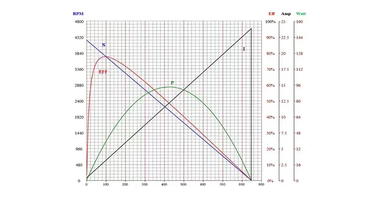
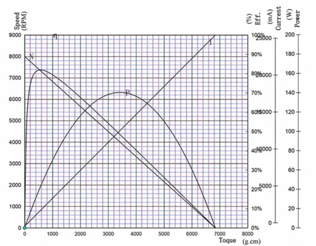
For a lower-speed, higher-torque outer-rotor example, see the TSL-BLDC-5520 outrunner motor and its performance curve.
Pumps, Spindles, and Power Tools
Inrunners are commonly selected for pumps, spindles and tools that require high shaft speed, fast response and a stationary outer housing. The housing can be located accurately in the equipment and connected to a metal structure for heat transfer.
The motor still has to be matched to the load curve. Centrifugal pumps and fans typically require rapidly increasing power as speed rises, while cutting tools may experience short, high-torque load changes.
Die TSL-BLDC-3163A inrunner motor is one example designed for a compact high-speed power-tool application.
Gimbals and Robot Joints
An outrunner is often a good choice when the motor drives a gimbal axis or rotary joint directly. Its larger radius supports torque at relatively low speed, and the hollow central area can help with bearings, shafts or cable routing.
An inrunner combined with a gearbox may be more suitable when the available motor diameter is limited or when the joint requires a larger reduction ratio. In this case, gearbox backlash, efficiency and reflected load inertia become part of the comparison.
Electric Mobility and Wheel Drives
An outrunner can provide a compact direct-drive or low-reduction solution for wheels and traction systems. However, its larger rotor inertia and rotating mass must be considered when the motor is installed in a moving wheel assembly.
An inrunner with a reduction stage can keep the motor diameter smaller and move the motor closer to the vehicle structure. The better solution depends on wheel speed, required grade torque, transmission efficiency, available space and acceptable system mass.
Enclosed Industrial and Medical Equipment
An inrunner is usually easier to integrate when the motor must sit inside a narrow enclosure, connect thermally to a machine frame or support a stationary sealed housing.
An outrunner can also be enclosed, but the designer must provide clearance around the rotating bell and a defined heat-transfer path from the stationary windings. Noise, vibration, cleaning requirements and allowable surface temperature should be verified in the complete device.
Fazit
If the choice has to be reduced to one rule, choose an inrunner when high speed, rapid response and a stationary outer housing are the priorities. Choose an outrunner when direct-drive torque, a short axial package and a larger torque-producing radius matter more.
That rule is only the starting point. The final comparison should be made at the actual operating point: loaded speed, continuous torque, peak-torque duration, current, temperature rise, duty cycle and load inertia. No-load rpm, Kv and stall torque are not enough to approve a motor for continuous operation.
If neither topology can meet the required speed and torque directly, an inrunner with a gearbox may be more practical than increasing motor diameter. Conversely, removing an unnecessary gearbox and using an outrunner directly may reduce parts and transmission loss. The better architecture is the one that meets the load requirement with acceptable temperature, size, efficiency and service life.
Need Help Comparing an Inrunner and Outrunner?
To compare the two motor topologies for a real application, provide the operating requirements rather than only the preferred motor diameter or Kv.
The most useful information includes:
- required loaded speed;
- continuous torque;
- peak torque and permitted peak duration;
- supply voltage and controller current limit;
- duty cycle and expected operating time;
- ambient temperature, enclosure and cooling method;
- available diameter, length, shaft and mounting space;
- load inertia and frequency of starting, stopping or reversing;
- Hall sensors, encoder or other feedback requirements.
TSL Motor can compare available inrunner and outrunner models or evaluate a custom winding and mechanical configuration. Send us your operating requirements for an engineering review.
FAQ
Q1:Can I Replace an Outrunner With an Inrunner That Has the Same Kv and Power Rating?
Not without checking the complete operating point. Two motors with the same Kv and advertised power may have different torque constants, continuous-current limits, rotor inertia, cooling requirements and maximum mechanical speeds. Also compare the loaded speed, continuous torque, phase resistance, controller compatibility, shaft dimensions and mounting arrangement. Matching Kv alone does not make two motors interchangeable.
Q2:Does a Lower Kv Motor Always Produce More Torque?
A lower Kv generally corresponds to a higher torque constant when the values use the same units and measurement convention. This means more torque per amp, not automatically more maximum or continuous torque. Actual torque capacity still depends on permitted current, winding resistance, magnetic saturation and the motor’s ability to remove heat.
Q3:Why Can Two Motors With Similar Kt Values Have Different Rated Torque?
Kt only states how much electromagnetic torque is produced per amp. Rated torque also depends on how much continuous current the winding can carry without exceeding its temperature limit. Motors with similar Kt values can therefore have different rated torque because of differences in winding resistance, copper volume, active length, cooling, ambient temperature and the manufacturer’s rating method.
Q4:How Do I Balance an Outrunner Motor?
Inspect shaft runout, bearings, magnet position, rotor-bell deformation and adhesive distribution before attempting a balance correction. Measure vibration amplitude and phase with suitable balancing equipment, then add or remove a controlled amount of mass at the indicated position. Balance the complete rotating assembly and retest it across the intended speed range. Randomly adding tape until the vibration feels lower is not a reliable production method.
Bürstenloser Gleichstrommotor
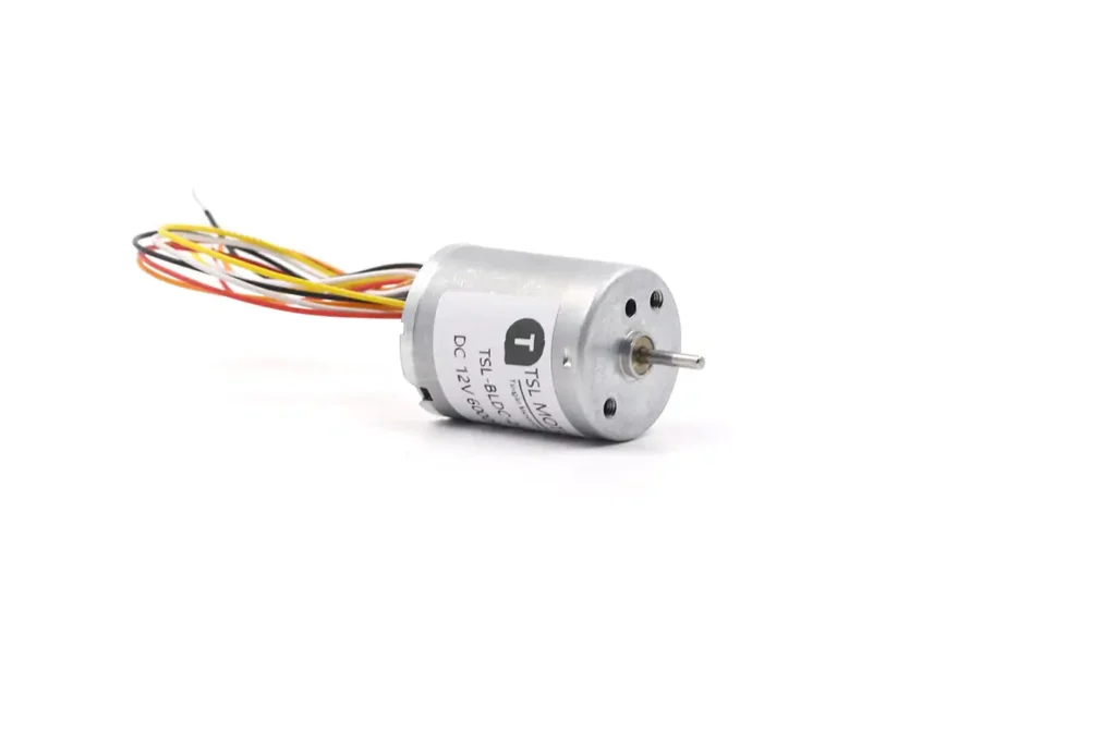
Brushless DC motors provide a solution to meet the demands for higher energy efficiency, longer lifespan, and quieter operation. As a leading manufacturer of BLDC motors,TSL Motors has developed the smallest BLDC motor, measuring just 6mm in diameter and 2mm in thickness, designed as a flat vibration motor.