Published: September 25, 2025
Updated: August 25, 2026
Brushless DC (BLDC) motors represent a transformative technology in modern electromechanical systems. Their core innovation lies in replacing traditional mechanical commutators with complex electronic control systems, thereby fundamentally overcoming many of the limitations inherent in their brushed predecessors.
This shift in design has not only improved motor performance metrics but has also given rise to new application fields, from high-precision aerospace to everyday consumer electronics. TSL-Motor is a leading DC motor manufacturer in China, offering high-quality brushless DC motors for many advanced applications.
Wichtigste Erkenntnisse
- A brushless DC motor replaces mechanical brushes and a commutator with electronic commutation.
- The controller energizes the stator phases according to the rotor position, causing the permanent-magnet rotor to produce continuous rotation.
- Rotor position can be determined using Hall sensors, sensorless back-EMF detection or higher-resolution feedback such as an encoder, depending on the control requirements.
- Inrunner, outrunner, slotted and slotless designs provide different tradeoffs in speed, torque density, inertia, package size, noise and heat dissipation.
- Motor selection should be based on the required speed and continuous torque under load, as well as voltage, current, duty cycle, temperature rise, feedback and driver compatibility.
BLDC Motor Definition and Main Components
Definition: An Electronically Commutated Synchronous Motor
Commutated System
A brushless DC motor is a permanent-magnet synchronous motor in which electronic switching replaces the brushes and mechanical commutator. The rotor carries permanent magnets, while the stationary stator contains the phase windings. During operation, the rotor follows the magnetic field produced by the sequentially energized stator phases, so the rotor speed remains synchronized with the electrical commutation frequency.
Although the motor system is supplied from a DC power source, the controller uses an inverter stage to switch current through the motor phases. Therefore, the phase windings do not simply receive continuous, fixed DC current. In engineering terminology, BLDC motors are often associated with trapezoidal back-EMF and six-step commutation, while permanent-magnet synchronous motors, or PMSMs, are often associated with sinusoidal back-EMF and sinusoidal or field-oriented control. In practice, these terms sometimes overlap because the same motor may be operated using different control methods.
Main Components of a BLDC Motor System
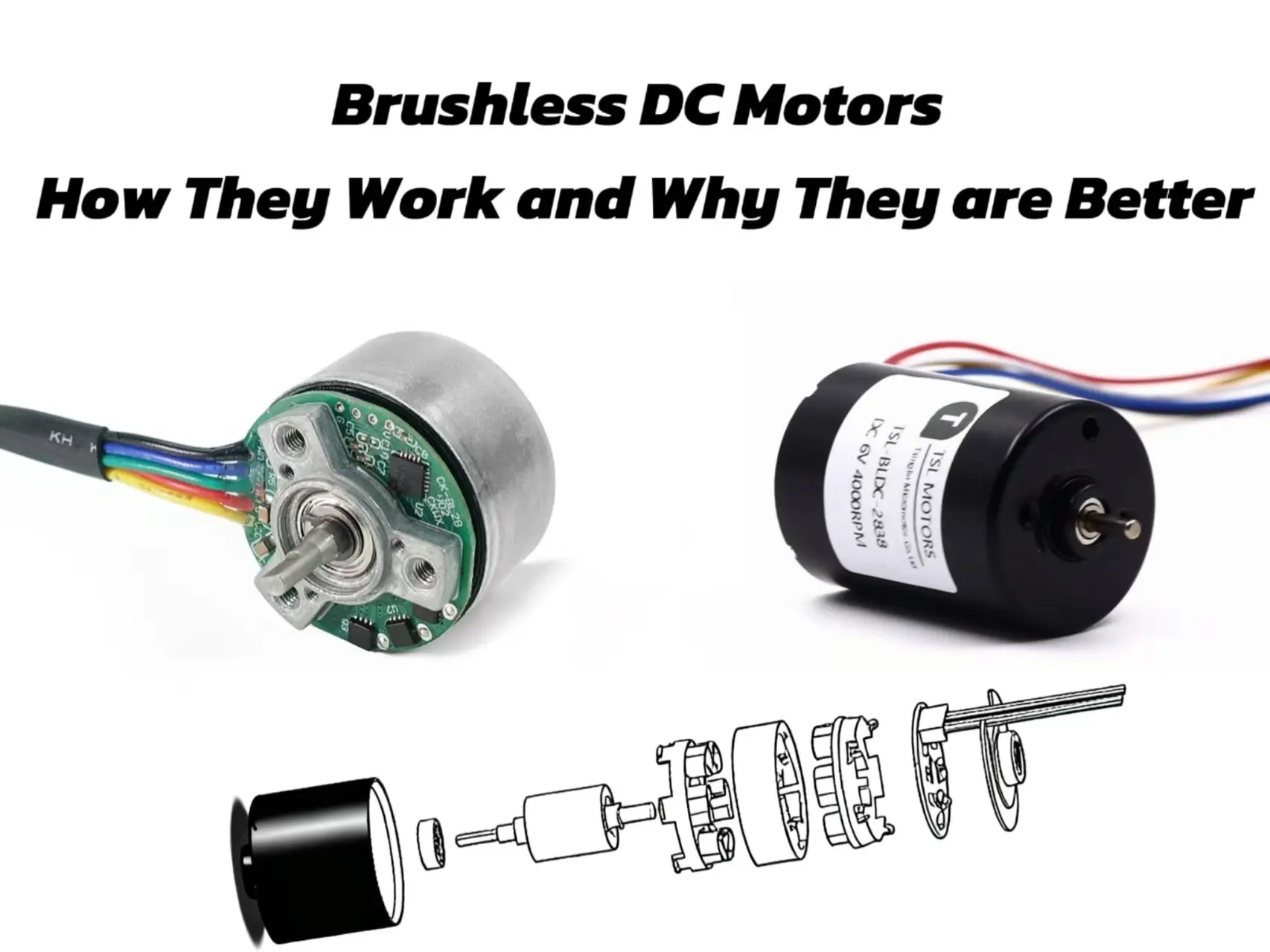
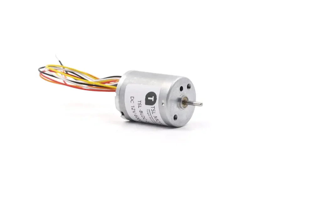
A complete BLDC motor system consists of the motor itself and the electronics required to commutate and control it. The motor contains two main electromagnetic components—the stator and rotor—while the driver or controller supplies the correctly timed phase currents. Depending on the control method, rotor-position information may come from Hall sensors, an encoder or sensorless estimation.
Stator
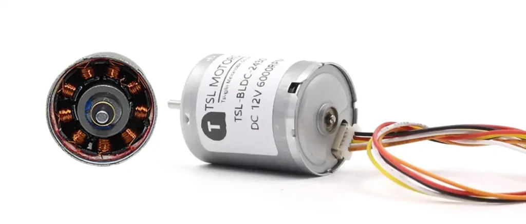
The stator is the stationary part of the motor and carries the copper windings. In a conventional slotted BLDC motor, the stator core is assembled from thin electrical-steel laminations that reduce eddy-current losses. The windings are normally arranged as three phases and may use a star (Y) or delta (Δ) connection, depending on the required voltage, current, speed and torque characteristics.
The winding design—including the number of turns, wire diameter, phase resistance and connection method—directly affects the motor’s speed constant, torque constant, current requirement and copper loss. Rated voltage alone is therefore not enough to evaluate a motor. Continuous output is also limited by winding temperature and the motor’s ability to transfer heat to its housing and surrounding structure.
Slotless BLDC motors use a different stator construction that reduces cogging torque and can provide smoother operation, but they also have different inductance, thermal and manufacturing characteristics.
Rotor
The rotor is the rotating part of the motor, where permanent magnets are mounted. To achieve high torque and high power density, the rotor typically uses high magnetic flux density rare-earth permanent magnet materials like Neodymium-Iron-Boron (NdFeB) and Samarium-Cobalt (SmCo).
The number of magnetic pole pairs on the rotor can range from 2 to 8 or more, depending on the application requirements, with poles arranged in an alternating North/South (N/S) sequence.
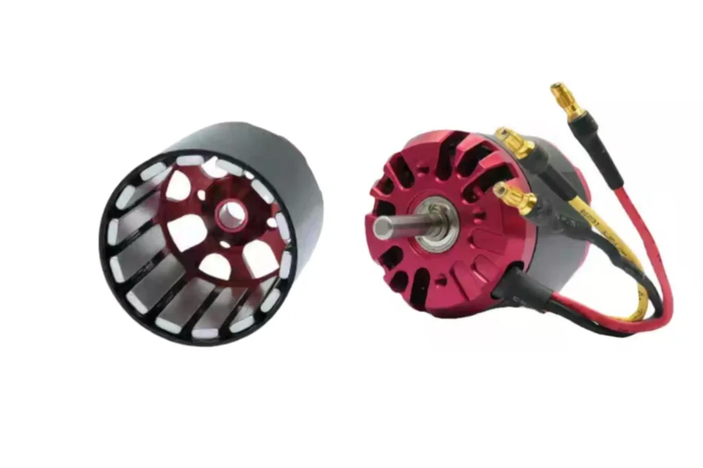
Rotor designs vary, with magnets being either Surface Permanent Magnet (SPM) or Interior Permanent Magnet (IPM). The IPM structure embeds the magnets inside the rotor, providing better mechanical integrity to withstand higher speeds.
Electronic Controller (ESC)
The electronic controller is the “brain” of the BLDC motor system, completely replacing the function of the mechanical commutator. This solid-state circuit typically consists of a microcontroller (MCU), gate drivers, and power switches (such as MOSFETs or IGBTs).
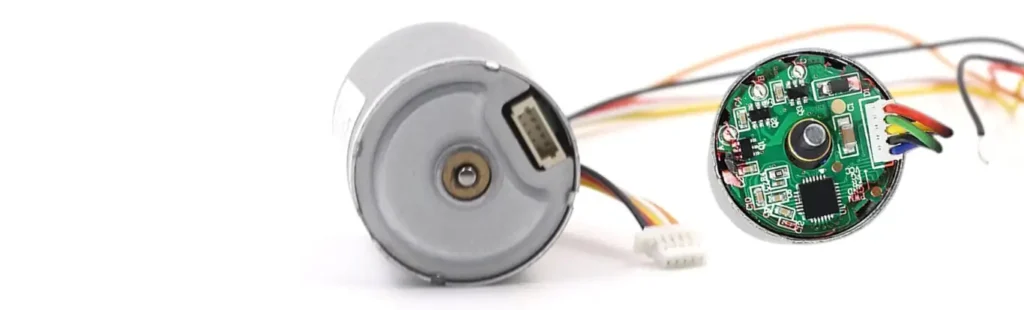
The controller’s main task is to monitor the rotor’s position in real time and, based on this information, switch the current in the stator windings with precise timing and sequence. Without the electronic controller, the BLDC motor cannot operate, making it an indispensable part of the system.
How Does a Brushless DC Motor Work?
The basic working principle of a BLDC motor follows the Lorentz force law. Its operation can be broken down as follows:
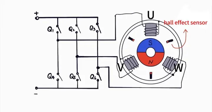
1️⃣The electronic controller applies a DC voltage to one of the three stator windings (e.g., U-phase and V-phase), generating an electromagnetic field in a specific direction within the stator.
2️⃣This stator magnetic field interacts with the permanent magnetic field of the rotor. According to the principle that like poles repel and opposite poles attract, a torque is exerted on the rotor’s permanent magnets.
3️⃣This torque drives the rotor to rotate, attempting to align its magnetic field direction with the stator’s magnetic field.
4️⃣Just before the rotor reaches the alignment position, the controller switches the voltage applied to the stator windings, changing the direction of the stator’s magnetic field (e.g., switching to the V-phase and W-phase).
5️⃣The new stator magnetic field again interacts with the rotor magnets, creating a new torque that forces the rotor to continue “chasing” this continuously changing magnetic field.
6️⃣By continuously switching the current in the stator windings at a very high frequency and in a precise sequence, the controller creates a smoothly rotating magnetic field in the stator, which drives the rotor to achieve continuous, stable rotation.
What Does “Brushless” Mean?
“Brushless” means that the motor does not use carbon brushes and a mechanical commutator to transfer current to rotating windings. In a brushed DC motor, the brushes maintain sliding electrical contact with the commutator. This contact gradually wears, produces brush dust and may create commutation sparks and electrical noise.
In a typical BLDC motor, the windings remain stationary and the rotor carries permanent magnets. The electronic driver switches current through the stator phases, so electrical power does not need to pass through brushes into a rotating winding. Eliminating the brush–commutator interface reduces this source of friction, wear and maintenance, although bearings, insulation, magnets and other components still limit motor service life.
Stationary windings can also provide a more direct thermal path to the motor housing, particularly in an inrunner design. However, heat dissipation still depends on the motor structure, housing, mounting surface, airflow, duty cycle and ambient temperature. An outrunner or a fully enclosed motor may have different thermal behavior, so brushless construction alone does not guarantee low temperature rise or high continuous output.
Electronic Commutation and Rotor Position Feedback
From Mechanical to Electronic: A Paradigm Shift
Electronic commutation has two related tasks: determining the rotor’s electrical position and applying the appropriate current to the stator phases. The controller must keep the stator magnetic field correctly oriented relative to the permanent-magnet rotor so that the motor continues to produce torque in the required direction.
Texas Instruments provides a useful technical overview of the differences between trapezoidal, sinusoidal and field-oriented BLDC commutation methods.
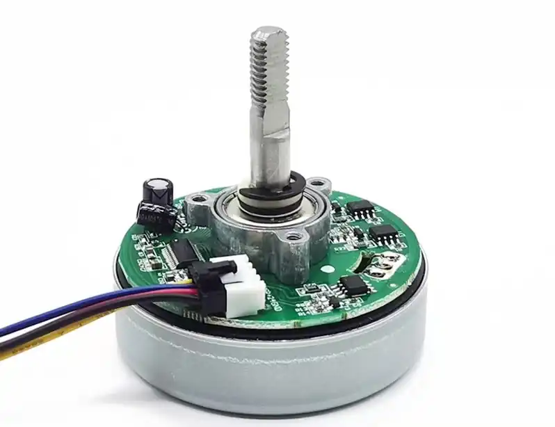
Commutation timing and current regulation are not the same function. Commutation determines which phases should conduct and in what direction, while PWM and current control regulate how much voltage or current is applied. Together, these functions allow the system to control motor speed, torque, direction, acceleration and braking. Position holding is also possible in a properly designed servo system, but it requires suitable position feedback, closed-loop control and continuous current.
How Does the Controller Determine Rotor Position?
The controller needs sufficient information about the rotor’s electrical position to commutate the motor correctly.
Rotor position can be obtained using Hall sensors, estimated without physical sensors, or measured using a higher-resolution encoder.
Hall-Sensor Commutation:
This is the most direct and reliable method, achieved by installing physical position sensors inside the motor. The most commonly used sensors are Hall effect sensors.
A typical three-phase BLDC motor will have three Hall sensors embedded, spaced 120 electrical degrees apart. As the rotor rotates, its permanent magnet poles (N or S) pass sequentially over these three sensors. Each sensor outputs a high or low signal based on the detected magnetic field polarity.
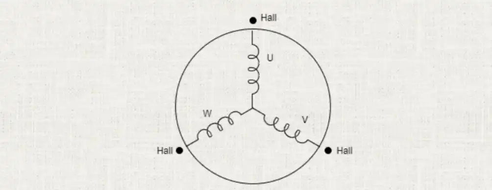
The combination of these three sensor signals (with six valid states in total) provides the controller with a real-time digital “map” of the rotor’s position, which the controller uses to decide which two windings to energize next.
The great advantage of the sensored approach is that it provides precise position feedback, ensuring smooth and reliable torque output, especially during motor startup, low-speed operation, and when the load changes dramatically.
Sensorless Commutation
Sensorless technology aims to reduce costs and simplify the motor structure by inferring the rotor position by monitoring the motor’s electrical characteristics, without physical sensors. Its core principle is the detection of Back-Electromotive Force (Back-EMF).
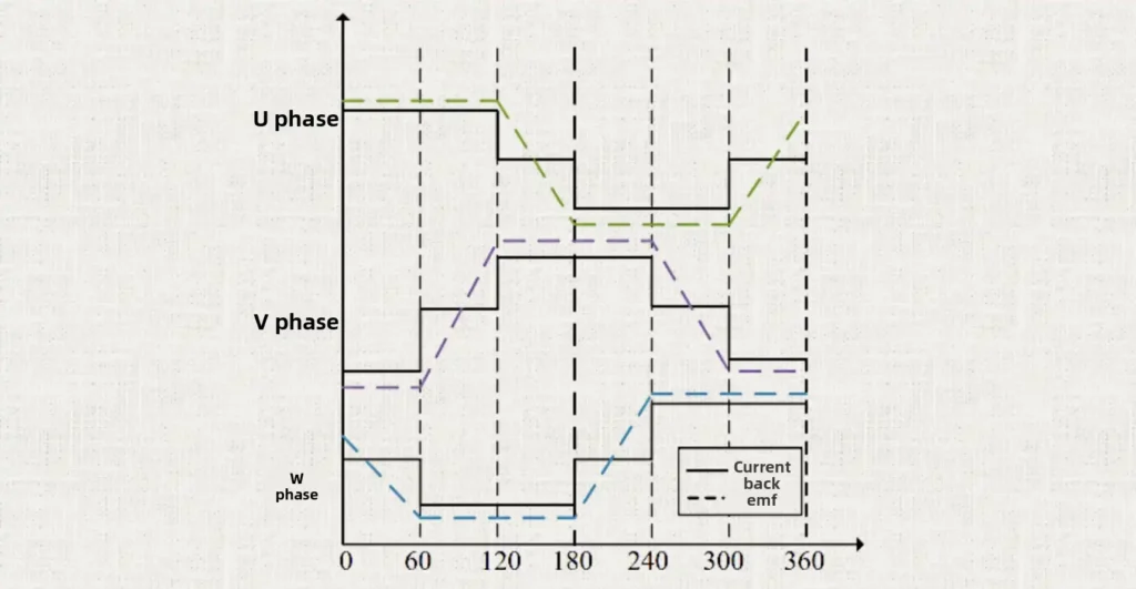
As the motor rotor rotates, its permanent magnetic field cuts through the stator windings. According to the law of electromagnetic induction, a voltage is induced in the winding that is not currently energized, which is the Back-EMF. The magnitude of the Back-EMF is proportional to the motor speed, and its zero-crossing point has a precise relationship with the position of the rotor’s magnetic poles.
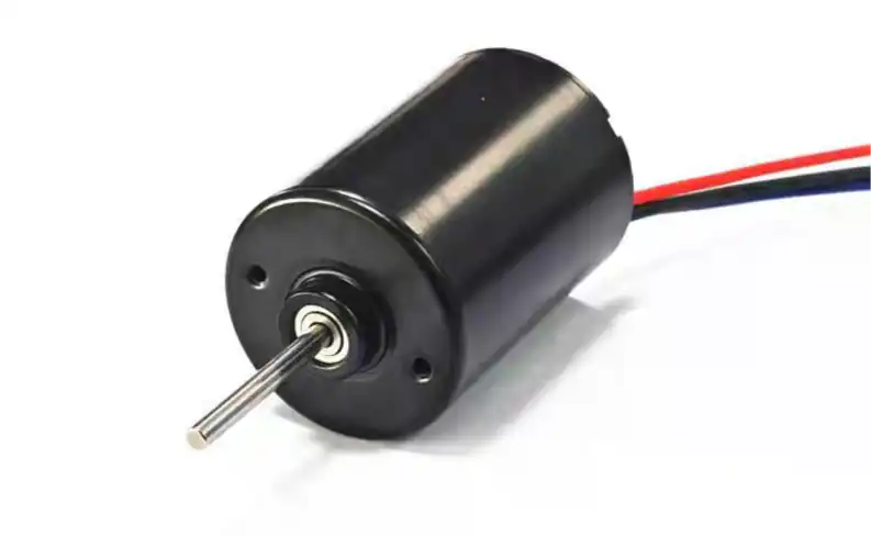
By monitoring the Back-EMF signal on this “floating” winding, the controller can infer the rotor’s position and determine the optimal commutation timing. Sensorless control is very effective and low-cost at medium to high speeds, but its challenge lies in the startup and very low-speed stages, as the Back-EMF signal is very weak and difficult to detect accurately when the speed is too low.
Encoder Feedback
An encoder provides higher-resolution speed and position information than standard digital Hall sensors. Incremental encoders commonly output quadrature A and B signals, with an optional index signal, while absolute magnetic or optical encoders can report the rotor angle directly through an analog or digital interface.
Encoder feedback is useful when the application requires precise speed regulation, low-speed smoothness, repeatable positioning or closed-loop position control. Depending on the system architecture, Hall sensors may still be used for initial commutation while the encoder supports the speed and position loops, or the controller may use the encoder angle directly for commutation.
The tradeoffs are additional cost, wiring, installation space, alignment requirements and controller complexity. Encoder resolution should therefore be selected according to the required output accuracy, motor pole count, maximum speed and control-loop bandwidth rather than simply choosing the highest available resolution.
Digital Hall Sensors
| Item | Details |
|---|---|
| Information provided | Rotor electrical sector |
| Startup and low-speed operation | Reliable from standstill |
| Main advantages | Simple, robust and suitable for six-step commutation |
| Main limitations | Coarse position resolution |
| Typical applications | Pumps, fans, gear motors and general automation |
Sensorless Back-EMF
| Item | Details |
|---|---|
| Information provided | Estimated commutation timing |
| Startup and low-speed operation | Limited at standstill and very low speed |
| Main advantages | Fewer components and wires |
| Main limitations | Requires a startup strategy and is unsuitable for precise positioning |
| Typical applications | Fans, blowers, high-speed spindles and cost-sensitive drives |
Encoder
| Item | Details |
|---|---|
| Information provided | High-resolution or absolute rotor position |
| Startup and low-speed operation | Strong low-speed and positioning performance |
| Main advantages | Precise speed and position control |
| Main limitations | Higher cost, more wiring and additional alignment requirements |
| Typical applications | Robotics, servo systems, medical devices and precision automation |
Brushless DC Motor Drive: Six-Step Commutation
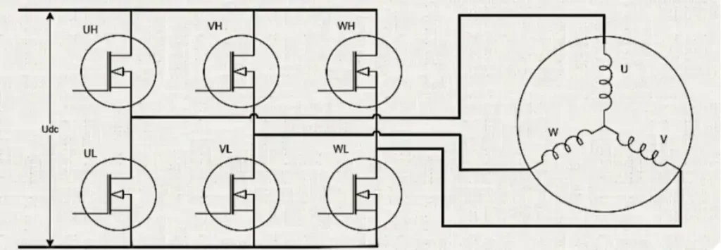
A three-phase BLDC motor is normally powered through an inverter rather than directly from the DC supply. One widely used control method is six-step commutation, also called trapezoidal or block commutation. It is relatively simple to implement and is commonly used when cost, reliable rotation and straightforward speed control are more important than extremely low torque ripple.
One electrical revolution is divided into six commutation states of 60 electrical degrees each. In each state, one phase is connected toward the positive DC bus, another phase is connected toward the negative bus, and the third phase is left floating. The controller advances to the next state according to the rotor-position information provided by Hall sensors or a sensorless estimation method.
The following is one example of a forward-rotation commutation sequence:
- U+ and V− conduct; W is floating.
- U+ and W− conduct; V is floating.
- V+ and W− conduct; U is floating.
- V+ and U− conduct; W is floating.
- W+ and U− conduct; V is floating.
- W+ and V− conduct; U is floating.
After the sixth state, the sequence repeats. Reversing the order reverses the motor direction. The exact phase order and its relationship to the Hall signals depend on the motor’s phase wiring, magnet arrangement and sensor installation, so the controller must use the correct commutation table for the specific motor.
These six states complete one electrical revolution, not necessarily one mechanical shaft revolution. A motor with multiple pole pairs completes several electrical revolutions during one mechanical revolution. Because the phase current changes at each commutation boundary, six-step control may produce torque ripple, vibration and audible noise, particularly at low speed.
BLDC Motor Speed and Torque Control
Speed Control
PWM, or pulse-width modulation, is commonly used to regulate the voltage applied through the inverter switches. Increasing the PWM duty cycle generally increases the effective phase voltage available to the motor, but motor speed is not determined by duty cycle alone. The resulting speed also depends on the supply voltage, winding characteristics, load torque, current limit, back-EMF and system losses.
In open-loop control, the controller applies a PWM command without correcting the result using measured speed. The actual speed may therefore decrease as the load increases. In closed-loop speed control, Hall transitions, encoder signals or sensorless estimates are used to calculate the motor speed. The controller then adjusts the PWM or current command to reduce the difference between the target speed and measured speed.
PWM frequency must also be selected carefully. A higher switching frequency can move switching noise above the audible range and reduce current ripple, but it also increases switching losses and controller heating. The appropriate frequency depends on the motor inductance, driver, switching devices, acoustic requirements and operating speed.
Torque Control
When the motor is correctly commutated and operating below magnetic saturation, output torque is approximately proportional to the torque-producing current. This relationship is commonly expressed as:
Torque ≈ Torque constant × Current
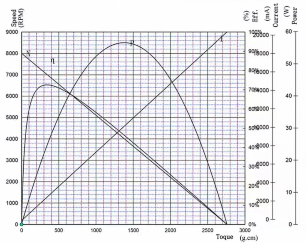
The controller can estimate or measure motor current using shunt resistors, Hall-effect current sensors or other current-sensing methods. A closed current loop then adjusts the inverter output to follow the commanded current and limit excessive current during startup, acceleration, load changes or a stalled condition.
Current control does not remove the motor’s thermal limits. Continuous torque is restricted by winding copper loss, iron loss, bearing loss, heat dissipation and the maximum permitted winding temperature. Peak torque may be available for startup or short acceleration periods, but it must be defined together with an allowable duration and duty cycle.
For motor selection, engineers should compare the required load torque with the motor’s rated or maximum continuous torque at the intended operating speed. Stall torque should not be used as the normal continuous operating point because the motor is not rotating, back-EMF is absent and current and winding temperature can rise rapidly.
Advanced BLDC Commutation Methods
Six-step commutation is relatively simple and cost-effective, but changing the conducting phase pair at each commutation boundary can produce torque ripple. The resulting vibration and audible noise depend on the motor’s back-EMF waveform, winding inductance, commutation timing, current regulation, mechanical load and structural resonance.
Sinusoidal commutation and field-oriented control regulate the phase currents more continuously than conventional six-step control. When the motor, feedback method and controller are properly matched, these methods can improve low-speed smoothness, acoustic performance and torque control. However, they require more processing capability, more detailed rotor-angle information and more careful system tuning.
Sinusoidal Commutation
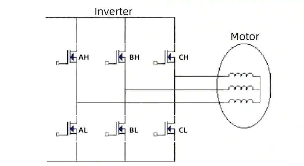
Sinusoidal commutation commands smoothly varying phase currents according to the rotor’s electrical angle. In a three-phase system, the current references are approximately sinusoidal and separated by 120 electrical degrees. Instead of abruptly changing between six discrete conducting states, the controller gradually changes the contribution of each phase as the rotor turns.
When the commanded current waveform is appropriately matched to the motor’s back-EMF, sinusoidal commutation can reduce torque ripple, vibration and audible noise compared with basic six-step control. The improvement is especially useful in applications requiring quiet operation or smoother low-speed rotation.
Sinusoidal commutation requires more detailed rotor-angle information than basic six-step control. An encoder, resolver, magnetic angle sensor or suitable sensorless estimator may be used. Standard digital Hall sensors can also be interpolated in some systems, but their coarse position information may limit low-speed smoothness and dynamic performance.
Field-Oriented Control (FOC)
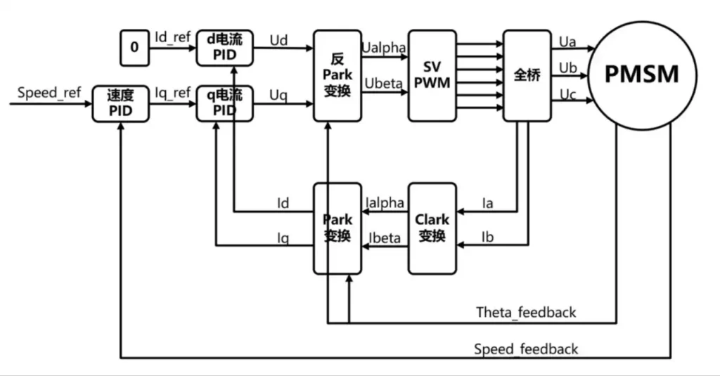
Field-oriented control, or FOC, is a vector-control method that regulates the motor current relative to the rotor magnetic field. The controller measures or estimates the phase currents and rotor electrical angle, then uses mathematical coordinate transformations to represent the current as two components: the d-axis component associated with magnetic flux and the q-axis component primarily associated with torque.
For many surface permanent-magnet motors, the d-axis current is normally controlled near zero while the q-axis current is adjusted to produce the required torque. Other motor structures and operating conditions may use different current commands, including field weakening when operation above the base speed is required.
Because FOC regulates the current vector continuously, it can provide smooth torque, strong low-speed performance and fast dynamic response. It is often selected for robotics, servo drives, medical devices and precision automation where torque quality and controllability are more important than minimum controller cost.
FOC requires accurate rotor-angle information or a suitable position estimator, phase-current measurement, sufficient processor performance and properly tuned control loops. Motor parameters, current-sensor accuracy, inverter dead time and software tuning all affect the final result. FOC can improve efficiency within a properly designed operating range, but it does not automatically guarantee the highest efficiency at every speed and load point.
Which BLDC Control Method Should You Choose?
The appropriate control method depends on the application rather than on which method is considered the most advanced.
- Six-step commutation is suitable when simple control, reliable rotation and lower controller cost are the main priorities. It is commonly used in fans, pumps, blowers and general-purpose gear motors.
- Sinusoidal commutation is useful when quieter operation and smoother rotation are required but the full dynamic capability of FOC is unnecessary.
- Field-oriented control is generally preferred when the application requires precise torque regulation, smooth low-speed operation, rapid response or servo-level control.
The motor and controller must also be matched. Back-EMF waveform, winding inductance, pole count, rotor-position feedback, supply voltage, current range and maximum operating speed all influence which method will provide the best system performance.
What Is The Difference Between Brushed And Brushless Motor
To visually summarize these differences, the table below provides a comprehensive comparison:
| Feature | Bürstenbehafteter Gleichstrommotor | Brushless DC Motor (BLDC) |
| Commutation | Mechanical (brushes & commutator) | Electronic (external controller & sensors/algorithms) |
| Core Structure | Wound rotor (armature), permanent magnet stator | Permanent magnet rotor, wound stator |
| Effizienz | Medium (60% - 80%) | High (85% - 90%) |
| Lifespan | Limited (by brush wear, 2,000-5,000 hours) | Very long (by bearings, >10,000 hours) |
| Maintenance | Requires periodic brush replacement | Generally maintenance-free |
| Speed Limit | Limited by mechanical commutation, lower speed | Only limited by mechanical strength, can achieve very high speeds |
| Torque Characteristics | Good startup torque | High torque-to-weight ratio, flat torque over wide speed range |
| Audible Noise | Higher (mechanical friction & electrical sparks) | Very low (only bearing noise) |
| EMI | Significant (commutation sparks) | Very low (no sparks) |
| Heat Dissipation | Poor (heat source is in the internal rotor) | Excellent (heat source is in the external stator) |
| Control Complexity | Simple (direct DC voltage application) | Complex (requires an electronic controller) |
| Initial Cost | Low | High |
| TCO | Higher (due to maintenance and energy consumption) | Lower (due to long life, no maintenance, and high efficiency) |
BLDC Motor Configuration Analysis: Inrunner vs. Outrunner
In an inrunner BLDC motor, the permanent-magnet rotor rotates inside the stator while the outer housing remains stationary. This structure often provides lower rotor inertia and a more direct path for transferring winding heat to the housing. In an outrunner motor, the rotor forms an external rotating bell around the stator. Its larger effective rotor radius and short axial profile can be advantageous in direct-drive applications requiring higher torque at lower speed.
These are general design tendencies rather than fixed performance rules. Actual torque, speed, inertia and temperature rise also depend on motor diameter, axial length, winding, pole count, magnet design, current and cooling conditions. For a detailed engineering comparison, see our guide to Inrunner vs. Outrunner Motors: Torque and Selection Rules.
Why Is A Brushless Motor Better
A brushless motor is often the better choice when an application requires long operating life, continuous duty, efficient use of limited power, or accurate speed and torque control. Removing the brushes eliminates brush wear, brush dust and commutation sparks, while electronic control allows the motor response to be adapted to the application.
However, brushless does not automatically mean better in every system. A BLDC motor requires a compatible driver and may involve higher initial cost, additional wiring, switching EMI and more complex control. A brushed DC motor can still be the practical choice for simple, cost-sensitive or intermittent-duty equipment. The decision should be based on performance at the actual operating point, thermal limits, duty cycle and total system cost.
Fazit
A brushless DC motor combines a permanent-magnet rotor, stationary stator windings and electronic commutation. Its performance depends not only on the motor structure but also on the feedback method, driver, control algorithm, load and thermal conditions. Hall-based six-step control, sensorless commutation, sinusoidal control and FOC each serve different cost and performance requirements.
Before selecting a BLDC motor, verify the required speed and continuous torque under load, supply voltage, current limit, peak-load duration, duty cycle, temperature rise, mechanical dimensions and driver compatibility. Inrunner, outrunner, slotted and slotless designs should be evaluated according to the actual operating point rather than general claims about which structure is best.
FAQ
Q1: Can a brushless DC motor run directly from a DC power supply?
A bare three-phase BLDC motor requires an electronic driver for commutation. Only products with an integrated driver can be connected directly to their specified DC supply.
Q2: Why does a sensorless BLDC motor struggle at startup or low speed?
Sensorless control commonly relies on back-EMF, which is absent at standstill and weak at low speed. Hall sensors or an encoder are generally better for loaded startup and very-low-speed operation.
Q3: Are Hall sensors accurate enough for position control?
Digital Hall sensors provide coarse rotor-sector information suitable for basic commutation. Precise positioning and smooth low-speed control normally require an encoder or magnetic angle sensor.
Q4: How do I match a BLDC motor with the correct driver?
Check voltage, continuous and peak phase current, feedback type, commutation method and control interface. The driver should also provide appropriate current limiting and protection.
Q5: Why does a BLDC motor vibrate or jerk instead of rotating?
Common causes include incorrect phase or Hall wiring, insufficient startup current, current limiting, sensorless startup failure or excessive load. Verify the wiring and commutation table before testing.
TSL MOTOR Brushless DC Motor Solutions
TSL Motor develops and manufactures miniature BLDC motors, brushless gear motors and integrated drive solutions for robotics, medical devices, automation and other precision applications. Our capabilities include motor winding and assembly, gearbox manufacturing, CNC machining, encoder integration and driver development.
Available configurations include inrunner, outrunner, coreless, sensored, sensorless and encoder-equipped motors. Customization can cover the winding, shaft, mounting interface, gearbox, feedback device and driver according to the application requirements.
Selected BLDC Motor Examples
- TSL-KW1510 15 mm Coreless Brushless Motor — a compact coreless configuration for applications with limited installation space.
- TSL-BLDC-2430 24 mm Inrunner BLDC Motor — an inrunner motor with published speed, current, torque and efficiency data.
- TSL-BLDC-WK1806 Frameless Outrunner Torque Motor — an outer-rotor configuration designed for integration into compact mechanical assemblies.
For motor selection, provide the supply voltage, loaded speed, continuous torque, peak torque duration, duty cycle, available installation space and feedback requirements. Contact the TSL Motor engineering team to evaluate the motor, gearbox, encoder and driver as one system