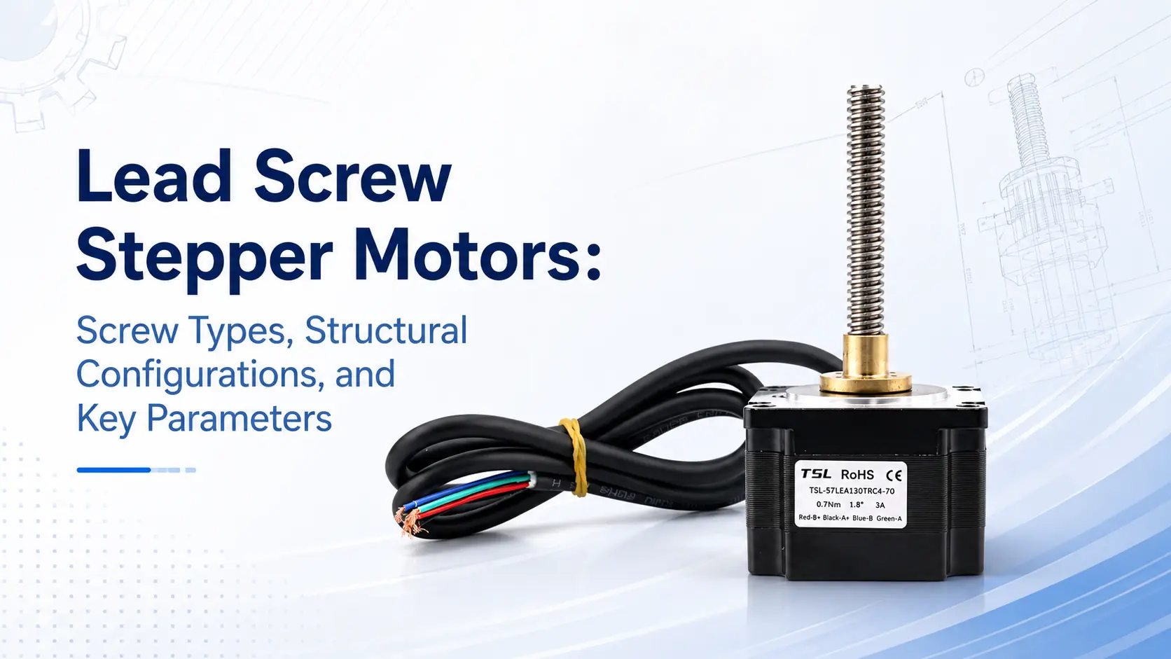
A lead screw stepper motor converts rotary motion into linear motion through a lead screw and nut mechanism, enabling precise positioning of a load. With a compact structure, simple control, and good repeatability, it is widely used in medical devices, optical instruments, automation equipment, and small linear drive systems.
Engineering selection often focuses on motor dimensions, electrical specifications, and holding torque while overlooking the key parameters of the lead screw. However, the screw specification, mechanical configuration, and axial clearance directly determine the actuator’s thrust, speed, resolution, noise, and service life, making them essential selection criteria.
Wichtigste Erkenntnisse
- Choose the right screw type.
- Match lead to speed needs.
- Smaller lead increases thrust.
- Larger lead increases travel speed.
- Check backlash and positioning accuracy.
- Use dynamic torque for calculation.
- Consider load, stroke, and installation.
Basic Operating Principle of a Lead Screw Stepper Motor
Each time a stepper motor receives a pulse, its rotor turns through a fixed angle. For example, a common 1.8° stepper motor requires 200 full-step pulses to complete one revolution. When the rotor is connected to a lead screw or lead screw nut, the threaded mechanism converts this rotary motion into axial linear motion.
The axial distance traveled by the nut during one revolution of the screw is called the lead. For example, with a 2 mm lead, the nut moves 2 mm for every screw revolution; with an 8 mm lead, it moves 8 mm per revolution.
Therefore, at the same motor speed, a larger lead produces a higher linear speed, while a smaller lead provides greater theoretical mechanical advantage. A smaller lead also results in less travel per step and generally offers higher theoretical resolution.
However, this does not mean that the smallest lead is always the best choice. Although a small lead can improve theoretical thrust and resolution, it may require the motor to operate at a much higher speed, where its dynamic torque can drop significantly.
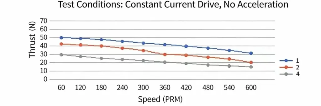
The lead should therefore be selected by considering the target speed, load, operating frequency, and the motor’s speed-torque characteristics.
Main Types of Lead Screws
Based on how force is transmitted between the screw and nut, common linear-motion screws can be divided into trapezoidal lead screws, Acme screws, ball screws, and planetary roller screws.
Trapezoidal Lead Screws
Trapezoidal lead screws are the most common type used in small lead screw stepper motors. Metric products generally use a trapezoidal thread profile, with common sizes including Tr4, Tr6, and Tr8.
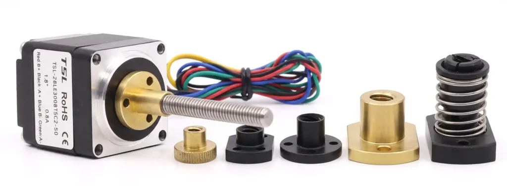
A trapezoidal lead screw transmits axial load through sliding friction between the screw thread flanks and the nut thread flanks. The nut may be made from engineering plastic, bronze, or another wear-resistant material.
Its main advantages include a simple structure, mature manufacturing processes, relatively low cost, low operating noise, and good tolerance of dust and minor contamination. With a small lead, the system may also provide a certain degree of resistance to back-driving. Typical applications include valves, medical devices, fluid-handling systems, laboratory automation, and compact positioning mechanisms.
Its primary limitation is relatively low transmission efficiency. During continuous high-speed or high-load operation, substantial frictional heat may be generated between the screw and nut. As the nut wears over time, axial clearance may also increase.
Trapezoidal lead screws are therefore better suited to low- and medium-speed applications with moderate loads, cost constraints, and requirements for relatively quiet operation.
Acme Screws
Acme screws are mainly used in inch-based designs. Their operating principle is similar to that of metric trapezoidal screws, and they also transmit load through sliding contact between the thread flanks.
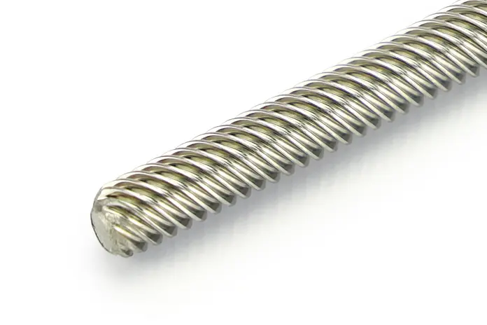
A typical Acme thread has a 29° included angle, while a metric trapezoidal thread commonly has a 30° included angle. Although the two profiles appear similar, they follow different dimensional standards, and their nuts are generally not interchangeable.
When selecting an Acme screw, confirm the following information:
- Whether the screw uses metric or inch dimensions;
- The units used for the diameter and pitch;
- The screw lead;
- The number of thread starts;
- The nut thread profile and fit class;
- The machining dimensions at the screw ends.
Acme screws are common in equipment designed for the North American market, while machinery designed primarily in millimeters generally uses metric trapezoidal screws.
Ball Screws
A ball screw contains recirculating balls between the screw shaft and nut, transmitting load through rolling contact. By replacing the sliding friction of a trapezoidal screw with rolling friction, it achieves higher efficiency, lower starting torque, and generally lower temperature rise.
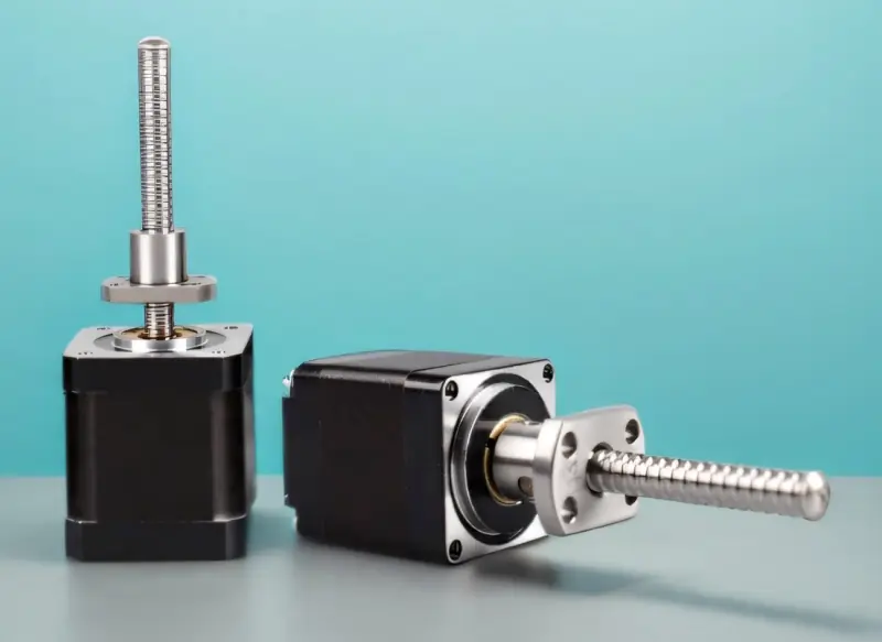
Ball screws are well suited to high-speed motion, frequent reciprocation, and precision positioning. Single-nut preload, double-nut preload, and similar configurations can reduce axial clearance while improving system rigidity and reversal accuracy.
Typical applications include automated linear stages, machine-tool feed axes, inspection equipment, precision press-fit systems, and linear mechanisms requiring high repeatability.
The main advantages of ball screws include:
- High transmission efficiency;
- Low starting resistance;
- Relatively low temperature rise;
- Suitability for higher operating speeds;
- Suitability for frequent reciprocating motion;
- Good positioning accuracy and repeatability.
The disadvantages of ball screws include higher cost and more demanding requirements for lubrication, sealing, installation alignment, and the operating environment.
Because ball screws have high transmission efficiency, they can be readily back-driven by the load in vertical installations. After power is removed, the load may rotate the screw in reverse and move downward. A brake, anti-drop device, or other mechanical locking mechanism may therefore be required.
Planetary Roller Screws
A planetary roller screw consists primarily of a screw, a nut, and multiple threaded rollers arranged around the screw. It is also commonly referred to simply as a roller screw.
During operation, each roller rotates about its own axis while orbiting around the screw axis. Axial load is transmitted simultaneously through multiple contact points between the rollers, screw, and nut.
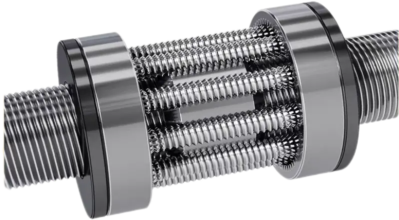
Unlike a ball screw, which uses balls as the load-carrying elements, a planetary roller screw uses threaded rollers. The resulting total contact area is larger. As a result, within a similar installation envelope, it can generally provide higher load capacity, greater axial rigidity, better impact resistance, and a longer duty-cycle life.
The main advantages of planetary roller screws include:
- High load capacity per unit volume;
- High axial rigidity;
- Suitability for frequent forward and reverse operation;
- Ability to withstand high impact loads;
- Suitability for high-thrust and high-duty-cycle applications;
- Low axial clearance when properly preloaded.
Planetary roller screws are commonly used in robotic joints, electric cylinders, servo presses, aerospace actuators, injection-molding equipment, test systems, and other high-thrust linear actuation systems.
For example, the TSL MOTOR SAG-1565 integrated planetary roller screw actuator combines the drive motor, planetary roller screw, bearing support, and push-rod output mechanism in one compact assembly, enabling high thrust and rigidity within a limited installation space.
Three Structural Configurations of Lead Screw Stepper Motors
In addition to the screw type, the mechanical arrangement between the motor and lead screw must also be considered. The three common configurations are external lead screw, non-captive, and captive.
External Lead Screw Type
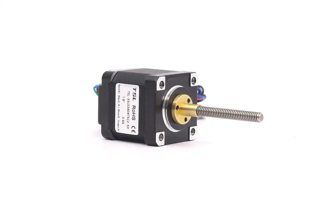
In an external lead screw configuration, the screw extends directly from the front of the motor. The motor rotates the screw, while an external nut travels axially along it.
This arrangement is suitable for use with linear guides, stages, slides, or external loads and provides considerable flexibility in stroke design. The screw length, nut type, and end machining can be selected according to the machine structure.

During installation, the screw, nut, and linear guide must be kept as parallel and coaxial as possible. The screw should not be subjected to significant radial loads, eccentric forces, or overturning moments.
If the screw is not parallel to the guide, or if the load is installed with an offset, friction, noise, and wear between the screw and nut will increase. In severe cases, this can cause binding, stalling, or loss of motor steps.
Non-Captive Type
In a non-captive configuration, the lead screw passes through a nut integrated into the motor rotor. As the rotor turns, the screw moves axially relative to the motor.
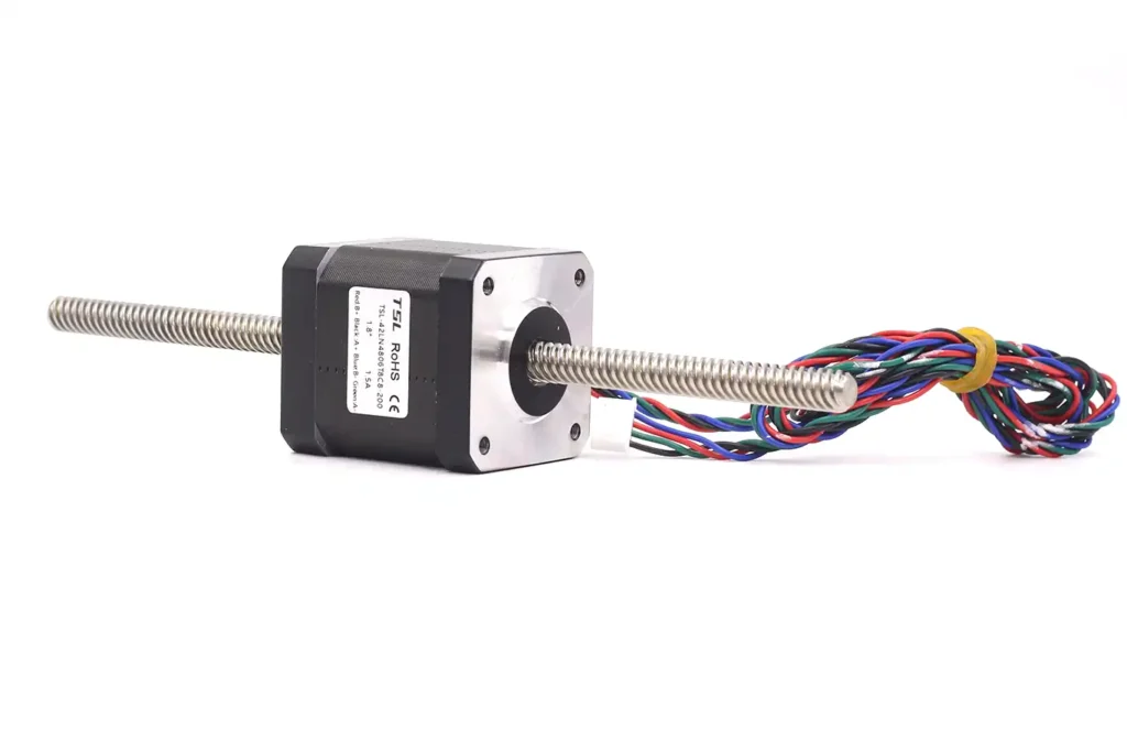
This arrangement can provide a relatively long stroke, but rotation of the screw itself must be prevented. The screw end is typically fixed to the load, while an external guide, guide sleeve, or load mechanism provides anti-rotation.
Without a reliable anti-rotation mechanism, the screw may rotate together with the internal nut instead of producing effective linear travel.
The non-captive configuration is suitable for long-stroke applications in which the machine can provide an independent guiding mechanism. However, the overall design must address screw anti-rotation, linear guidance, and end connection requirements.
Captive Type
In a captive configuration, the actuator contains an internal anti-rotation and guiding mechanism. When energized, the output shaft can extend or retract directly.
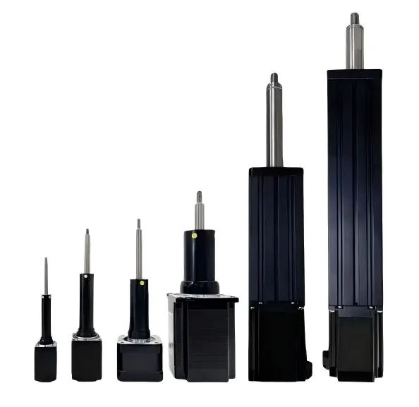
This configuration is easy to install because the user does not need to design an additional anti-rotation mechanism. It is suitable for short-stroke pushing and pulling, valve adjustment, fluid handling, and compact automation equipment.
The main limitation of a captive actuator is that its maximum stroke is generally restricted by the internal structure and overall length. When determining product dimensions, the effective stroke, retracted length, and total length with the output shaft fully extended must all be considered.
Basic Lead Screw Parameters
Nominal Diameter
The nominal diameter generally refers to the outside diameter of the lead screw. It affects the screw’s overall rigidity, load capacity, and permissible rotational speed.
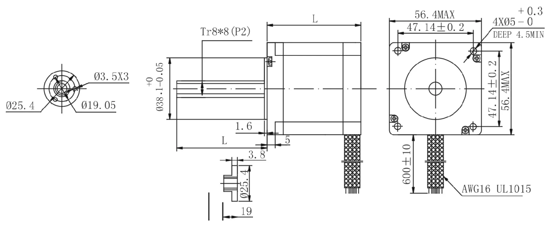
In general, a larger diameter provides greater rigidity and allows the screw to carry a higher axial load. Long, slender screws are more likely to whip at high rotational speeds. When subjected to compressive axial loads, they must also be checked for column buckling.
The smallest screw that fits the available space should therefore not be selected without further analysis. Stroke, speed, support arrangement, and load must also be evaluated.
Pitch and Lead
Pitch is the axial distance between corresponding points on two adjacent thread forms. It is normally represented by P and expressed in millimeters.
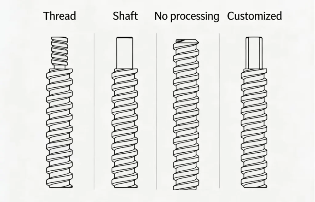
Lead is the actual axial distance traveled by the nut or output shaft during one complete screw revolution. It is normally represented by L and expressed in mm/rev.
The relationship between lead and pitch is:
L = P × Z
where:
- L is the lead;
- P is the pitch;
- Z is the number of thread starts.
For a single-start screw, the lead equals the pitch. For a double-start screw, the lead is twice the pitch. For a four-start screw, the lead is four times the pitch.
For example, with a pitch of 2 mm, a single-start screw has a lead of 2 mm, a double-start screw has a lead of 4 mm, and a four-start screw has a lead of 8 mm.
Number of Thread Starts
The number of thread starts is the number of independent helical threads formed on the screw.
A single-start screw has one continuous helix, a double-start screw has two independent helices, and a four-start screw has four independent helices.
The number of starts can be calculated as follows:
Z = L ÷ P
A multi-start screw increases the lead without requiring a proportionally larger thread pitch, thereby increasing the linear travel per screw revolution.
However, as the lead increases, the mechanical advantage generally decreases, travel per step becomes larger, and the tendency to back-drive increases. Multi-start screws are therefore more suitable for applications that prioritize speed over theoretical resolution and self-locking capability.
Lead Angle
The lead angle is the angle of the screw helix relative to a plane perpendicular to the screw axis. It can be approximated by:
λ = arctan[L ÷ (π × dm)]
where:
- λ is the lead angle;
- L is the lead;
- dm is the screw pitch diameter;
- π is the mathematical constant pi.
For screws of the same diameter, a larger lead results in a larger lead angle.
A larger lead angle generally helps improve transmission efficiency and linear speed, but it reduces mechanical advantage and makes the screw more susceptible to back-driving.
A smaller lead angle generally improves theoretical thrust and resistance to back-driving, but friction losses may increase and operating speed may be limited.
Stroke
Stroke is the usable linear travel that the actuator can actually deliver. The total screw length is not equal to the effective stroke.
The following dimensions must be deducted during the design process:
- Nut length;
- Bearing installation length;
- Machined length at the screw ends;
- Limit-switch or end-stop allowance;
- Safety allowance;
- Space occupied by the motor’s internal structure;
- Length occupied by the output-shaft connection.
For an external lead screw configuration, it must also be confirmed that the nut will not run off the usable threaded section anywhere within the full stroke.
For a captive configuration, check that the output shaft will not interfere with surrounding components in either the fully extended or fully retracted position.
Axial Clearance
Axial clearance is the lost motion between the screw and nut during direction reversal and is also known as backlash.
When screw rotation changes from one direction to the other, the motor may turn through a small angle before the nut or output shaft begins moving in the reverse direction. This motion that produces no effective axial travel is the axial clearance.
Axial clearance directly affects bidirectional positioning accuracy, although it may have little effect on repeatability when motion always occurs in the same direction.
Common methods for reducing axial clearance include:
- Using an anti-backlash nut;
- Using a preloaded double-nut arrangement;
- Using a spring-preload mechanism;
- Using a preloaded ball-screw nut;
- Improving the fit accuracy between the screw thread and nut.
Preload should not simply be maximized. Excessive preload increases friction torque, operating temperature, and nut wear, which can reduce system efficiency and service life.
Fazit
The performance of a lead screw stepper motor is determined not only by the motor itself, but also by the screw type, structural configuration, and fundamental mechanical parameters.
After the basic configuration has been selected, linear speed, travel per step, dynamic thrust, and load requirements must be calculated and verified against the motor’s available dynamic torque at the target operating speed.
Reliable selection is possible only when the motor, screw, nut, bearings, linear guides, and actual operating conditions are evaluated as a complete system.
Linearaktuator Schrittmotor
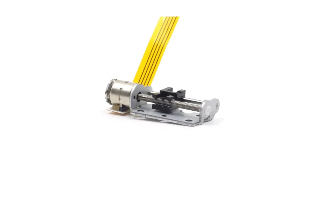
TSL Motor’s Stepper Motor Linear Actuators convert rotary motion into precise linear movementby using lead screws or slider mechanisms.From micro stepper linear actuators for camera iris control,to NEMA stepper motor linear actuators for 3D printers and automation systems.Different sizes and thrust levels support different applications.
At TSL, linear actuators go beyond mechanical structures.
Standard wires or FPC flexible cables are available.Each solution can be optimized for system-level requirements.
Here, you don’t need to worry about technical challenges.
Our engineering experts work closely with you.We solve problems together and develop solutions together.